© 2016, IRJET | Impact Factor value: 4.45 | ISO 9001:2008 Certified Journal
| Page 1633
Comparative Performance Evaluation of Different Compensating
Current Generation Techniques for Shunt Active Power Filter
Ketan T. Kadivar
Lecturer, Department Of Electrical Engineering, L. E. College Morbi-363642, India,
---***---Abstract -
This paper presents application of different reference compensating current calculation techniques for shunt active power filter. The reference compensating current has been calculated by instantaneous PQ theory, d-q reference frame theory and unit vector template generation technique. Comparative analysis of different reference compensating current calculation techniques on the performance of shunt active power filter has been carried out. The simulation study has been performed on MATLAB simulink.Key Words: Active Power filter (APF), Power quality, Total Harmonics distortion (THD), point of common coupling (PCC).
1. INTRODUCTION
Extensive use of power electronics equipments like rectifiers, variable speed drives have caused an increase of harmonic disturbances in power systems. Harmonic causes many problems like low power factor, excessive neutral current, transformer overheating, capacitor blowing, motor vibration etc. To enhance power quality, harmonics need to be eliminated. The active power filter can solve problem of harmonic elimination and satisfies the reactive power demand of non linear load.
For low voltage level most compensator for APF use a standard two level voltage source inverter. It can improve power quality by harmonic elimination and raising load power factor. The shunt active power filter injects compensating current in the grid and source current becomes sinusoidal. Literature suggests various compensating current calculation techniques. The most popular techniques are instantaneous P-Q theory [1], unit vector template generation technique [2] and d-q reference frame theory [3, 6]. All the techniques are effective for harmonics elimination and reactive power compensation.
As the load harmonics may be complex, change rapidly and randomly, APF has to respond quickly with high control accuracy in current tracking. The inverter tracks the reference compensating current by hysteresis current control method. The hysteresis current control technique offers several advantages like, appropriate
stability, fast transient response, simple implementation and operation, high accuracy, inherent current peak limitation, overload rejection, compensation of effects due to load parameters changes and semiconductor voltage drops of the inverters [4, 5].
2. SYSTEM CONFIGURATION AND CONTROL
SCHEME
FIG-1: Basic structure of shunt active power filter
© 2016, IRJET | Impact Factor value: 4.45 | ISO 9001:2008 Certified Journal
| Page 1634
3.
INSTANTANEOUS POWER THEORY
Three phase instantaneous reference compensating current can be calculated with the instantaneous power theory. Three phase instantaneous source voltage and current can be converted into α-β coordinates as following equations.
c b a β αv
v
v
2
3
2
1
2
3
2
1
0
1
3
2
v
v
(1) c b a β α i i i 2 3 2 1 2 3 2 1 0 3 2 i
1
i
(2)The instantaneous real power p and instantaneous imaginary power q are defined from the instantaneous phase voltages and line currents from the α-β axes as
β α α β β αi
i
v
v
v
v
q
p
(3)
q
p
v
v
v
v
i
i
α β β α 1 β α (4)These two powers have constant values and a superposition of oscillating components as follows
q
~
q
q
p
~
p
p
(5)Where
p
and~
p
represents the average and oscillating parts of p, whereasq
andq
~
represents the average and oscillating parts of q. The average valuep
represents the energy flowing per time unity in one direction only. The oscillating partp
~
represents amount of additional power flow in the system without effective contribution to energy transfer from source to load or load to source. The average value ofq
represents conventional three phase reactive power and does not contribute to energy transfer. The oscillating component of the imaginary power~
q
is the power that is exchanged between three phases, but does not contribute in power transfer between source and load. Compensation ofp
~
andq
~
results in elimination ofharmonics from source current and compensation of
q
results in unity power factor.
q
p
~
v
v
v
v
I
I
α β β α 1 cβ cα (6) cβ cα * cc * cb * ca i i 2 3 2 3 0 2 1 2 1 1 3 2 i ii
(7)4.
UNIT VECTOR TEMPLATE GENERATION
TECHNIQUE
To get unit vector template signal, the input source voltages are sensed and multiplied by gain equal to 1/Vm.
(Vm is equal to peak amplitude of fundamental voltage).
(8)
The peak value of reference current can be calculated by regulating the DC bus capacitor voltage of the inverter. The actual capacitor voltage is compared with reference value and error signal is processed in PI controller.
e(t) = Vref – Vact (9)
(10)
Ideal compensation requires source current to be sinusoidal and in phase with its phase voltage. The estimated source current after compensation is given by,
(11)
Reference compensating current required to be generated by APF is given as,
© 2016, IRJET | Impact Factor value: 4.45 | ISO 9001:2008 Certified Journal
| Page 1635
5.
SYNCHRONOUS REFERENCE FRAME THEORY
The three phase instantaneous load current can be converted into d-q coordinate as shown in following equation.
(13)
Where, θ is the angular position of the synchronous reference frame. The current in the d-q coordinates can be decomposed into average and oscillating parts using low pass filter,
(14)
(15)
The oscillating component is responsible for harmonics in the load current. The reactive power demand of the load can be supplied by ilq current. The
shunt APF should supply and ilq, in order to fulfill
harmonics and reactive power demand of the load. The reference compensating current in the d-q axis is given by eq.
(16)
The reference compensating currents in the abc axis is obtained by using inverse park transformation.
(17)
6.
RESULT AND DISCUSSION
The proposed schemes have been simulated and
tested by MATLAB Simulink power system toolbox.
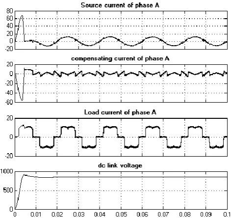
Fig. 2 shows the simulation results of shunt active
power filter based on Instantaneous PQ theory. The
load current is non sinusoidal and rich in harmonics.
The shunt APF supply the harmonics and reactive
power demand of the load and supply current becomes almost sinusoidal and in phase with its supply voltage. Fig. 3 [a] shows the harmonics spectrum of the load current
drawn by the diode bridge rectifier with R-L load. The load current contains significant 5th and 7th order harmonics
[image:3.595.39.272.185.236.2]and total harmonics distortion of the load current is 30.17%. Fig. 3[b] shows the harmonics spectrum of the source current after compensation.
Fig-2: Performance of SAPF with instantaneous PQ theory
[image:3.595.313.549.190.412.2] [image:3.595.318.546.481.710.2]© 2016, IRJET | Impact Factor value: 4.45 | ISO 9001:2008 Certified Journal
| Page 1636
Fig-3 [b]: harmonics spectrum of source current for instantaneous PQ theory
Fig-4[a]: Performance of SAPF with UVTG technique
Fig. 4 [a] shows the performance of UVTG technique for harmonics compensation. The THD of the source current is only 2.61 % as shown in fig. 4 [b]. The advantages of the scheme are better regulation of dc bus voltage, less distortion in source current and unity power factor operation.
Fig. 5 [a] shows the simulation result of shunt APF controlled by d-q reference frame algorithm. Fig. 5 [b] indicates the harmonics spectrum of source current. The total harmonics distortion is quite low and comparable with UVTG techniques. The main advantages of the proposed scheme are low THD of source current and
Fig-4[b]: Harmonics spectrum of source current for UVTG technique.
Fig-5 [a]: Performance of SAPF with synchronous d-q reference frame algorithm.
reactive power compensation. Fig. 6 indicates ability of control scheme to generate balanced source current under unbalanced supply voltage. Before 0.04 second, shunt APF is not connected with the grid. So source current is same as load current, which is unbalanced and distorted. At 0.04 second, APF is connected to grid and then after source current becomes balanced and sinusoidal.
[image:4.595.314.552.87.324.2] [image:4.595.40.278.97.329.2] [image:4.595.50.267.370.565.2] [image:4.595.330.534.372.563.2]© 2016, IRJET | Impact Factor value: 4.45 | ISO 9001:2008 Certified Journal
| Page 1637
balanced mains voltage. But it is not able to provide balanced current against unbalanced mains voltage. The instantaneous PQ theory provides reasonably sinusoidal current. The performance of synchronous d-q reference frame is excellent for harmonics and reactive power compensation under un balanced supply voltages.
Fig-6: Response of SAPF under unbalanced supply voltage after switched on at 0.04 S
Table-1: Performance Evaluation of Control Techniques
Performance criteria
Without APF
With APF
(Controlled by three algorithm)
Instantaneous P-Q theory
UVTG technique
Synchronous d-q Reference
frame
THD (%) 30.17 5.8 2.61 2.64
Performance Against un
balanced supply voltage
- Better poor best
Dc link voltage settling time
(s)
- 0.6 0.15 0.4
7.
CONCLUSION
This paper compares the performance of three current compensation technique for shunt active power filter. As stated before, all the three control algorithms viz. instantaneous P-Q theory, unit vector template generation technique and d-q reference frame theory, are found to be quite effective for harmonics compensation. The result of the comparison shows the superior performance can be obtained by synchronous d-q reference frame theory. The
effectiveness of APF for all the techniques is found effective to meet IEEE-519 standard recommendations on harmonics level.
REFERANCES
[1] H. Akagi, Y. Kanazawa, A. Nabae, “Instantaneous reactive power compensators comprising switching devices without energy storage devices,” IEEE Trans. On Industry Applications, 1984, Vol. 1A-20, pp. 625-630.
[2] S. N. Gohil, M. V. Makwana, K. T. Kadivar, G. J. Tetar “Three Phase Unified Power Quality Conditioner (UPQC) For Power Quality Improvement by Using UVTG Technique” Proceedings of the 2013 International Conference on Renewable Energy and Sustainable Energy [ICRESE’13]
[3] Khadkikar, Vinod, et al. "Implementation Of Single-Phase Synchronous dq Reference Frame Controller For Shunt Active Filter Under Distorted Voltage Condition." Power Electronics, Drives and Energy Systems (PEDES) & 2010 Power India, 2010 Joint International Conference on. IEEE, 2010.
[4] M. P. Kazmierkowski, and L. Malesani, "Current control techniques for three-phase voltage-source PWM converters: a survey," IEEE Trans. Ind. Electron., vol. 45, no. 5, October 1998, pp. 691-703.
[5] B. K. Bose, "An adaptive hysteresis-band current control technique for a voltage-fed PWM inverter for machine drive system," IEEE Trans. Ind Electron., vol. 37, no. 5, October 1990, pp. 402-408.
[6] Bhim Singh, P. Jayaprakash and D.P. Kothari. “New control approach for capacitor supported {DSTATCOM} in three-phase four wire distribution system under non-ideal supply voltage conditions based on synchronous reference frame theory.” International Journal of Electrical Power & Energy Systems, 33(5):1109–1117, 2011
BIOGRAPHY:
![Fig-4[a]: Performance of SAPF with UVTG technique](https://thumb-us.123doks.com/thumbv2/123dok_us/8199235.815179/4.595.40.278.97.329/fig-performance-sapf-uvtg-technique.webp)
