Development of Wireless Light Control System
Based on Zigbee
Changfei Guo, Xiaoping Zou, Chaoting Ma, Rongrong Zhang
Beijing Key Laboratory for Sensor, Beijing Information Science and Technology University, Beijing, China Email: [email protected]
Received 2012
ABSTRACT
This paper presents a solution to wireless light control system based on Zigbee. Overall design framework of the system was introduced and analyzed in detail, which contained realization of hardware design. The Zigbee wireless light con-trol system was established based on CC2430-chip of Texas Instruments (TI). In this paper, we achieved designing Printed Circuit Board (PCB) for sensor nodes as end device and coordinator in Protel DXP 2004 and also wrote C codes in IAR embedded workbench development tool to form wireless network. Test results of system show that lights on end device or router in Zigbee wireless sensor networks (WSN) can be controlled by another switch on coordinator, which achieved remotely wireless intelligence light control.
Keywords: Wireless Light Control; Zigbee; PCB; WSN
1. Introduction
With the emergence of the internet of things, the princi-ples that gave rise to the internet are now leading to a new kind of network of everyday devices, an “Internet-0” [1]. As a new short-range wireless communication tech-nology, Zigbee aims at solving the function of internet among different hardware devices, which have powerful potential applying in intelligence control [2] such as in-dustry, medical and home.
To realize intercommunication among different hard-ware devices, we built wireless sensor networks (WSN) to achieve wireless light control. In this paper, design and implementation of system were given and analyzed in detail.
2. System Scheme
The architecture of system including hardware and soft-ware were analyzed and discussed as follows. Figure 1 is the system scheme applying in Zigbee wireless light con-trol network. There are mainly three types of sensor nodes to form a wireless network, which are coordinator, router and end device. Wireless communication was achieved by using CC2430-chip named Zigbee module [3]. Each coordinator is a control centre, which is re-sponsible to manage the whole network. Light module as end device or router can send signals to coordinator or another router. After achieving lower computer pro-gramming, coordinator processed data from routers and
[image:1.595.310.539.598.727.2]end devices. It means that the coordinator is similar to a switch which aims at controlling lights by wireless way in network. Router plays the role of information trans-mission, which must be a Full Function Device (FFD) with function of sending and receiving data. End device can be a Reduced Function Device (RFD), which is only used for sending or receiving data. To manage the whole network and process complicated data, coordinator usu-ally is connected to computer as control centre via RS- 232 serial communication port. Through the control cen-tre, we can easily know the condition of network and handle problems happened at any time we need. In this paper, wireless control was mainly carried out in hard-ware system by lower computer programming with c codes. Management software with Zigbee tree structure network [4] as control centre with graphic user interface (GUI) will be the next aim we consider.
3. Hardware Design
3.1. Key Light Control Circuit
For developing the whole light control system, all circuits related to the network must be designed and tested. To finish this part work, Protel DXP 2004 is a good design tool for us to choose. The next procedure we will demon-strate the global design process of the hardware system.
All parameters such resistors and capacitors were set precisely before according to circuit function by us. Fig-ure 2 is the key light control circuit we have designed, which mainly contains JPx (JP1 and JP2) module and JTAG module. JP1 and JP2 are slots of light module with CC2430-chip which has dual lines with entire 40 pins. For making circuit enable to be programmed, JTAG module with 10 pins is used for meeting design require-ment. S8 is the reset switch of light module. Remaining
[image:2.595.147.445.268.731.2]pins in circuit are linked to other correlative circuits we used in system. Figure 3 is the switch control circuit, which aims at implementing wireless control. This part circuit includes six switches, one capacitor and some re-sistors. S1 named UP and S5 named RIGHT are applied in intercommunication among different sensor nodes. Ac-cording to different voltages on switch node, CC2430- chip as MCU can detect which switch is pressed. When a sensor node joints into Zigbee wireless network, switch S5 will be used. In contrast, if a sensor node exits from Zigbee wireless network, S5 will be enable again. S1 is control switch on coordinator, which controls other lights on end device or router. By making use of this approach, lights on different end devices and routers can be con-trolled by switches on coordinator. Printed Circuit Board (PCB) of the whole circuit will be given in next section and test results will be analyzed as well.
Figure 2. Key hardware circuit of light control.
[image:2.595.148.448.306.505.2]3.2. PCB Design and 3D View
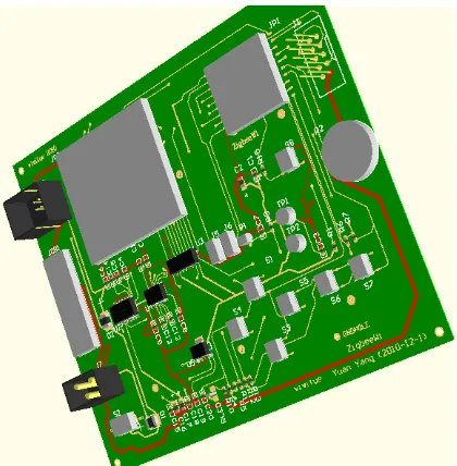
[image:3.595.59.289.295.477.2]After finishing circuit schematic design, the next prob-lem is how to change the design circuit into PCB for fab-rication. To solve the problem, we built all footprints for all chips and all devices. According to chip data sheets and devices we used, all device pin parameters were measured precisely by us with vernier caliper. Our PCB contained two layers, which is the top layer and bottom layer. Top layer is used to place main devices and bottom layer used to place batteries. After achieving auto and manual placing and routing with no errors through De-sign Rule Check (DRC), the final complete PCB board is shown in Figure 4. From the PCB board, our circuit is designed successfully. Figure 5 is the Board in 3D view. When fabrication comes to an end, we will see the final board.
Figure 4. PCB design of hardware circuit.
Figure 5. Board in 3D view.
3.3. Fabrication
Completed design all needed, we submitted PCB docu-ment to manufacture for fabrication. Figure 6 is final board of hardware circuit after finishing welding all de-vices. Test results were discussed in section 5.
4. Low Computer Software Programming
4.1. Programming Tool-IAR Embedded Workbench
Low computer software programming is the core part of whole Zigbee wireless. Without software development platform, hardware system can’t do anything, let along achieving intercommunication like information islands [5] communication. For making our system with networking, we wrote many functions with C codes to accomplish wireless communication and data transmission. At last we programmed C codes into 128KB-flash memory of CC2430-chip. Microcontroller on CC2430-chip can run exe files compiled by C codes to build Zigbee wireless light control network. All these tasks were done with no errors in IAR embedded workbench software platform.
4.2. Key Light Control Algorithm
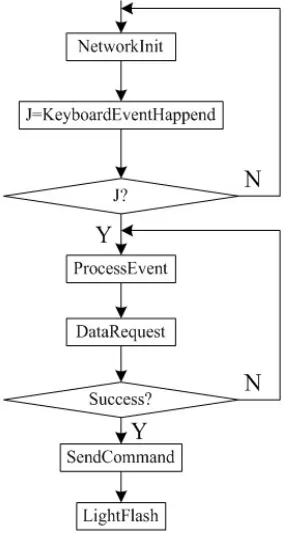
[image:3.595.68.278.505.719.2]Achieving wireless communication is not a simple job. On the contrary, it needs amount of large work to write c codes. For meeting requirement of networking, we only analyzed the key algorithm which is used for wireless light control. Figure 7 is the key light control algorithm flow diagram to implement wireless control. First, ini-tializing the whole network before keyboard event hap-pening, we wrote function with C codes to detect which keyboard event happened and processed this event. Sec-ond, light on end device or router will send data request according to event process result. If this process goes without any problems, control command will be sent to end device or router from coordinator. Light on end de-vice or router will be lighted or flashed. In the next sec-tion we will see the experiment result discussion.
[image:3.595.341.505.579.719.2]5. System Tests and Results Analysis
5.1. Hardware Networking
[image:4.595.71.272.246.728.2]Analysis aims at solving areas of problems, while design focuses on creating solution to problems. All problems in design solved, the next step is how to build a Zigbee wireless network with hardware board. Based on finish-ing programmfinish-ing in IAR development tool, we built our Zigbee wireless light control network. Figure 8 showed the hardware networking. One of three boards plays the role of coordinator and other two boards play the role of end device and router. We built a wireless network with three boards.
[image:4.595.102.245.254.521.2]Figure 7. Key light control algorithm.
Figure 8. Wireless light control networking.
5.2. Test and Result
Figure 8 is the testing system structure. Blue LEDs are the power indicator light. Coordinator as control centre is the core of the whole system. Router and end device are the object that controlled by coordinator. When wireless network built successfully after lower computer pro-gramming, the coordinator module showed Zigbee net-work ID as controlled node. On end device and router, red lights were used to represent networking success and green ones were used to be controlled light. Switch named S1 discussed in previous section on coordinator can control green lights on end device and router, while using witch S5 can joint or exit the networking for ap-plication. Figure 8 showed the green light status that the end device was lighted by switch on coordinator. Router was turned off by coordinator as well, in the mean time S5 on router was pressed to exit the network.
6. Conclusions and Future Work
In this paper, we have designed successfully the hard-ware circuit to apply in building Zigbee wireless light control network and also have given the test results of the system. From the results from Fig.8, we clearly see the implementation of wireless light control. Based on our development system, it is speculated that the present study is very helpful to design a large wireless network including more end devices and routers applying in real projects. However, there are still some problems not solved in our system such as how to manage the whole network with software when more end devices and rou-ters included. And our future aim is to design a light con-trol system including management software. And then we will manage the network well we build through our software with GUI.
7. Acknowledgements
This work has been partially funded by the Program of Beijing Key Lab for Sensor under Grant No.KF20111077205.
REFERENCES
[1] N. Gershenfeld, R. Krikorian and D. Cohen, “The Internet of Things,” Scientific American, Vol. 91, 2004, pp. 76-81.
doi:10.1038/scientificamerican1004-76
[2] J. Yick, B. Mukherjee and D. Ghosal, “Wireless Sensor Network Survey,” Computer Networks, Vol. 52, 2008, pp. 2297-2230. doi:10.1016/j.comnet.2008.04.002
[3] I. -K. Hwang and J. -W. Baek, “Wireless Access Moni-toring and Control System based on Digital Door Lock,”
IEEE Transactions on Consumer Electronics, Vol. 53, 2007, pp. 1724-1727. doi:10.1109/TCE.2007.4429276
of Tree-based ZigBee/IEEE 802.15.4 Wireless Net-works,” Computer Communications, Vol. 33, 2010, pp. 454-460. doi:10.1016/j.comcom.2009.10.013