http://dx.doi.org/10.4236/cs.2013.48064
Design and Digital Implementation of Controller for
PMSM Using Extended Kalman Filter
Mamatha Gowda, Warsame H. Ali, Penrose Cofie, John Fuller
Department of Electrical and Computer Engineering, Prairie View A&M University, Prairie View, USA Email: [email protected], [email protected], [email protected], [email protected]
Received October 19, 2013; revised November 19, 2013; accepted November 26,2013
Copyright © 2013 Mamatha Gowda et al. This is an open access article distributed under the Creative Commons Attribution License, which permits unrestricted use, distribution, and reproduction in any medium, provided the original work is properly cited. In accor- dance of the Creative Commons Attribution License all Copyrights © 2013 are reserved for SCIRP and the owner of the intellectual property Mamatha Gowda et al. All Copyright © 2013 are guarded by law and by SCIRP as a guardian.
ABSTRACT
A novel digital implementation of speed controller for a Permanent Magnet Synchronous Motor (PMSM) with distur- bance rejection using conventional observer combined with Extended Kalman Filter (EKF) is proposed. First, the EKF is constructed to achieve a precise estimation of the speed and current from the noisy measurement. Second, a propor- tional integral derivative (PID) controller is developed based on Linear Quadratic Regulator (LQR) to achieve speed command tracking performance. Then, an observer is designed and its error is utilized to provide load disturbance compensation. The proposed method greatly enhances the PMSM performance by reducing the control signal variation as well as the disturbance. The speed control performance is significantly improved compared to the case when we have an observer acting alone. The simulation results for the speed response and variation of the states when the PMSM is subjected to the load disturbance are presented. The results verify the effectiveness of the proposed method.
Keywords: Permanent Magnet Synchronous Motor; Extended Kalman Filter; PID; Vector Control; Observer
1. Introduction
Permanent Magnet synchronous Motor (PMSM) has a high torque/inertia ratio, high speed, high efficiency as well as high reliability and is of compact size. These qualities render PMSM as one of the most applicable AC machines for servo control applications and PMSM is therefore gaining extensive research attention in recent years [1-3]. PMSM weighs less and is of low mainte- nance; it offers many advantages in the high performance application areas such as in robotics, aerospace, naviga- tion and many more. The modeling and control of the PMSM is complex because of two main reasons: 1) the multi-input nature of the motor, 2) the coupling between the stator current and rotor speed are non-linear. For high performance of PMSM that drives the vector control the- ory is applied, in which 3-ф stationary frame transforms into 2-ф synchronously rotating rotor reference frame; thus the flux and torque can be controlled independently, similar to the DC motor [4-6]. Though, the vector control is a complex control technique, the progress in the de- velopment of fast semiconductors switches and cost effi- ciency micro-controller has made the vector control fea-
sible. PMSM uses known rotor shaft position as well as the inverter to control the armature currents,andis usu- ally employed in direct drive system. The direct drive systems are more prone to load variations and these va- riations directly impact the motor shaft; this deteriorates the performance of the system. In order to mitigate these defects, the disturbance rejection control technique is used.
In this paper a vector control method is developed and implemented by means of a conventional observer com- bined with Extended Kalman Filter algorithm to provide the speed control and disturbance rejection. In the vector control method, to achieve better control performance, it is important to know the information of the rotor speed and position. Here, state space representation of the model and observer is obtained. Utilizing the state space model, a PID controller is designed using Linear Quad- ratic Regulator (LQR) approach [7]. Commonly, the aim of the observer design is to reduce the observation error, but it is used to serve as feed forward compensation for the load disturbance in the proposed method [8].
frequency signal injection method, adaptive control the- ory, fuzzy control, state observer, EKF [9-16]. In all, EKF is more attractive as well as popular and is conti- nuously being used in research and applications because it delivers rapid, precise, and accurate estimation. In many applications EKF is implemented because of its low-pass filter characteristics [17,18]. The feedback gain used in EKF achieves quick convergence and provides stability for the observer.
In this article, the conventional observer combined with the Extended Kalman Filter is presented. The accu-rate estimation of states is very essential to achieve better control and performance of the PMSM drives. Here the EKF is utilized for the precise estimation of the rotor speed and stator q-axis current. Since the drive speed and drive current are measured directly from the machine terminals contain noise, they are not precise for speed control. In the proposed approach, the speed and q-axis current are estimated accurately by introducing EKF al-gorithm theory. The estimated current acts as an input to the state observer while the estimated speed is compared with the reference speed. The proposed method yields a smooth and quick speed tracking, reduction in the dis-turbance applied to the system, and better control of the control signal variation. The overall system performance is greatly enhanced with the proposed method.
2. Model of PMSM
The stator voltage and stator flux linkages equations in the rotor references frame are [4]:
d d
sd s sd s sd m s
v R i L i L i
t
sq, (1)
dd
sq s sq s sq m s sd fd
v R i L i L i
t
, (2)
sd L is sd fd
, (3)
sq L is sq
(4) where vsd, vsq, isd, isq, sd, sq are d-axis and q-
axis voltages, currents and flux linkages respectively.
s
R , Ls are the stator winding resistance and
induc-tance.
The electromagnetic torque generated and the accel- eration is given by:
2
em fd sq
p
T i , (5)
d d
em L
mech mech
T T B
t J J
, (6)
2
m m
p
ech (7)
where mech is the speed of the motor and p is the
number of poles.
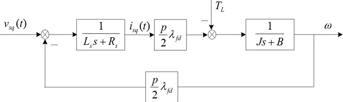
Since the torque developed by the motor is directly proportional to the motor drive current, it is difficult to control the drive current directly. Therefore the drive current is indirectly controlled through the input voltage. The simplified model of the PMSM q-axis subsystem is shown in Figure 1.
In vector control, assuming ids = 0, the state-space
model of the PMSM q-axis subsystem is derived as [8]:
1 2
0 2
fd s
s s sq
sq
s sq mech
mech fd
R p
L L i
i
L v
p B
J J
(8) For the speed controller design, the system output is
0 1
sq mechi y
(9)
If the motor output is considered as the drive current, then the motor output is given by:
1 0
sq mechi y
(10)
3. PID Parameters Tuning with
State-Feedback and State-Feed forward
LQR
The controller is designed as a single-input—single-output
(SISO) system. The following discussion is based on the
) (t vsq
L
T
s ss R
L 1
B Js
1
fd
p
2fd
[image:2.595.131.466.617.717.2]p
2 ) (t isqq-axis controller/observer design [8].
The state space model of the simplified PMSM, , with reference to the q-axis is:
1
G s
1 1 1 1 1 , 1 0 10
x t A x t B u t x x (11a)
1 1 1
y t C x t (11b)
where,
2 1 1x t R , 1 , , and A1, B1 and C1 are constant matrices.
u t R1 1
2
1 1
y t R
The entire system output is the sum of the motor out-put and load disturbance and is given by:
1
y t y t d t (12)
where y t
R1 1 , d t
R1 1The state space model of the speed controller, G2
s ,can be written as:
2 2 2 2 2 , 2 0 20
x t A x t B u t x x
, (13a)
2 2 2 1
y t C x t u t , (13b)
2 c
u t y t E r t
2 1
(13c)
where x t2
R , u2
t R1 1 , y2
t R1 1 , , and
r t R1 1 A2, , , are constant matri-
ces. 2 2
C Ec
B
In order to convert the PID tuning problem to an opti- mal design, we modify the closed loop cascade system into an augmented system with . The result is the following equation:
0
d t
1
e e e e e
x t A x t B u t E r t (14a)
1
e e e
y t y t C x t (14b)
where
1 1
2
2 1 2
1 1 2 0 0 , , 0 , 0
e e e
c
e e
A B
A B E
B E
B C A
x t
x C C
x t , 2 2 .
The resulting state-feedback LQR for the augmented system is:
1 e e 1 1
u t K x t K x t K x t (15)
where 1 2 1
K R , K2R1 2 .
The quadratic cost function for the system J, is given as:
T T
1 1
0 e e d
J
x t Qx t u t R u t t (16) where , , which represent the states varia-tion and control energy consumpvaria-tion, respectively.0
Q R0
The optimal state-feedback control gain which mini-mizes the performance index is given by:
1 T
e e
K R B P
. (17)
The solution of the revised Riccati equation is given by:
T 1 T 0e e e e
P A hI A hI PPB R B P Q (18) where P0, h0.
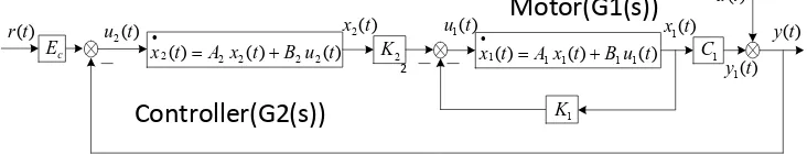
The motor states feedback actually act as the propor- tional and derivative controller
K x t1 1
respectively and the controller act as an integral only. Then K2 is a gain for the integral controller. Hence, the total control law is equivalent to a PID controller. By choosing the desired values of h and the weighting matrices Q and R, the control gain can be determined. The block diagram of the designed augmented system including the controller is shown in the Figure 2.The calculated control gains are given by:
1 0.2241 0.0030
K , (19a)
2 0.1333
K . (19b)
4. Design of Observer
A state observer is constructed mainly to achieve the speed control and disturbance rejection. The observation error and properly adjusted observer gain can provide feed-forward compensation for the output disturbance.
Suppose the state space model of the PMSM G s1
is:
1 1 1 1 1
x t A x t B u t , (20a)
1 1 1
y t C x t (20b)
with the entire system output being the sum of the motor output and load disturbance as :
1
y t y t d t
. (21)
The design of an observer, whose dynamic function is the same as that of the motor is as follows (see Equation (22)): ) ( 2t x ) (t r ) ( 1t y ) ( 1t u ) ( ) ( )( 2 2 2 2
2 t A x t B u t
x
) ( ) ( )
( 1 1 1 1
1t Ax t Bu t
x
[image:3.595.56.287.426.551.2] 2 K ) ( 2t u 1 C
Motor(G1(s))
Controller(G2(s))
c E ) ( 1t x ) (t d ) (t y 1 K 2 [image:3.595.114.480.648.718.2]
1 1 1 1 1 1 1
ˆ ˆ o ˆ
x t A x t B u t J C x t y t (22) where x tˆ1
is an observed state and x t1
isstate.
the real
Then
1 1ˆ
1 1
o 1 1ˆ
1 1
1 ˆ
x t A x t B u t J C x t C x t d t (23) The observation error is expressed as:
The observation error dynamic f
by:
ˆ
e t x t1 x t1
.
(24)unction is then given
Applyingthe Laplace transform, we
. (26)
above equation it is clear that the o e evitably exist due to the load di an
1 o 1 o
e t A J C e t J d t (25) get
1 o 1
oe s sI A J C 1J d
sFrom the bservation
rror will in sturbance,
d then the observed-state feedback can be regarded as:
1 1ˆ 1 1 1
K x t K x t K e t (27)
where, the term K x t1 1
1is the exact mo back, while the term
tor state feed-
K e t comes from
n in th
bance. Also th
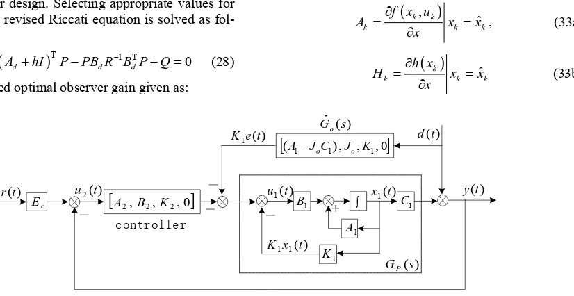
the observa- tion error. The P roller system including the ob- server structure is show e Figure 3.
The feedback of the observation error actually acts as feed forward compensation for the load distur
ID cont
e proper adjustment of the observer gain makes sure that the system is less affected by the load disturbance and provides additional feed forward compensation.
The speed signal differentiated through the position output of the encoder is very noisy. Thus isd instead of
mech
can be regarded as the system output in the fol- lowing observer design. Selecting appropri values for and R, the revised Riccati equation is solved as fol- lows [8]:
T 1 T0
d d d d
P A hI A hI PPB R B P Q
(28) ate
1 T
T 118.1727120.6678
o d
J R B P
(29)
where T1
d
A A , Bd C1T,
T 1
d
C B .
5. Sta
te Obse ver Bas
r
ed
Exten ed Kalman
d
Filter
al eq hich produces the optimal estimation of the
“(11b)” is the non-linear system. To ap- pl
The Extended Kalman Filter is a set of mathematic uations w
state system based on least square method. The EKF es- timates the process by using a feedback control. The EKF provides considerable good tolerance for the mathe- matical model error and noises in the measurement inac-curacy [19].
The state space model of the simplified PMSM given by “(11a)” and
y the EKF algorithm, the system needs be discretized and linearized [20].
The discrete approximated equation is given by:
1 (30a)k k k
x IAT x BTu ,
k k cx
y . (30b)
The nonlinear stochastic equation is:
1,
k k k (31)
x f x u
1
1 2 , 1 2 fd s
sq mech sq
s s s
k k
fd
sq mech
T
TR p T
i v
L L L
f x u
Tp B i J J (32) The Jacobian matrices of the partial derivative of f and h with respect to x are:
k, k
k
f x u h, Q
yields the desired optimal observer gain given as:
ˆ
k k
A x x
x
, (33a)
k ˆk k
h x
k
H x x
x
(33b)
) (s GP
) (
1e t K
) (t
r y(t)
controller
c
E B1 C1
1 A 1 K ) ( 1 t u
(A1JoC1),Jo,K1,0
) (
1 1x t K ) (t d ) ( ˆ s Go ) ( 2 t
u
x1(t)0 , , , 2 2
2 B K
[image:4.595.308.541.321.476.2]A
[image:4.595.119.532.509.722.2]The motor nonlinear state equations given in the dis- cretized form is as follows:
k
1,
k k k
x f x u w
, (34a)
k
k k
y h x v (34b) where and are zero-mean White Gaussian noise process and m ent noise with covariance Q and R. Mainly, there are two states in the Extended Kalman Filter, namely the prediction state and the correction state.
In the prediction state also called the time p
k
w vk
easurem
update, the o timal state estimate ˆx and state covariance P are predicted.
1
T 1
ˆ ˆ , ,0
Time u
ˆ ˆ
pk k
pk k k k
x f x u
P A p A Q
pdate (35)
In th correction state also called the measurement update, the predicted state estimate ˆ
e
x and covariance matrix P are corrected as follows:
1T T
ˆ ˆ
k pk k k pk k
K P H H P H R
ˆ ˆ ˆ Measurement update
ˆ ˆ
ck pk k k k pk
ck
x x K y H x
P I K H P
k k pk
(36) The important and difficult part in th
EKF is choosing the proper values for the covariance m
variance matrices affects both the dynamic and steady- state. By using trial and error method, a suitable set of values of Q and R are selected to insure better stability and convergence time.
The chosen values of Q, R and P are:
e design of the
atrices Q and R [21,22]. The change of values of co-
0.008 0 1 0
0.02
0 1.5 0 1
Q R P
(37)
6. Simulation Results
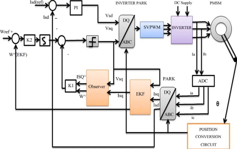
The PMSM model is constructed to verify he speed con- disturbance rejection using the conventional
nd K2 and opti-
m d the filter gain
is obtained using EKF algorithm. The output d rent and speed are estimated through the obser
and EKF algorithm is implemented using S-Function nction block is taken directly
. The noise-free, accurately t
trol and load
observer combined with EKF. The simulation is imple- mented using MAT Lab/Simulink. The parameter of the motor model is given in Table 1. Based on optimal con-
trol theory, the desired control gain K1 a al observer gain (Jo) are determined an
rive cur- ver theory
block. The input to the S-Fu from the machine terminals
estimated output current is fed to the observer as input while the estimated speed is compared with reference speed. At the output, the motor response is checked and the disturbance rejection is observed. The block dia- gram used in the simulation is as shown in the below Fi- gure 4 and the simulation results are shown in Figures 5-10.
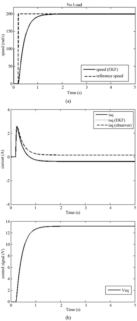
[image:5.595.99.495.467.716.2]With the reference speed of 200 rad/s, the simulation
Table 1. PMSM parameter.
Variable Physical Meaning Value Unit
s
R Armature Resistance 0.1127
s
L Armature Inductance 3.63e−4 H
J Moment of Inertia 1.2677e−4 Kg m 2
B Damping Coefficient 2.4857e−4 N m rad s
fd
Stator Flux Linkage 0.0131 V rad s
p Poles number 10
0 L
T Static Friction 0.0237 N m
(a)
(a)
(b)
Figure 6. (a) Speed response; (b) control signal response for observer combined with EKF (no load).
results with observer acting alone and observer com ined with EKF are shown in Figures 5 and 6, under no load
oothly.
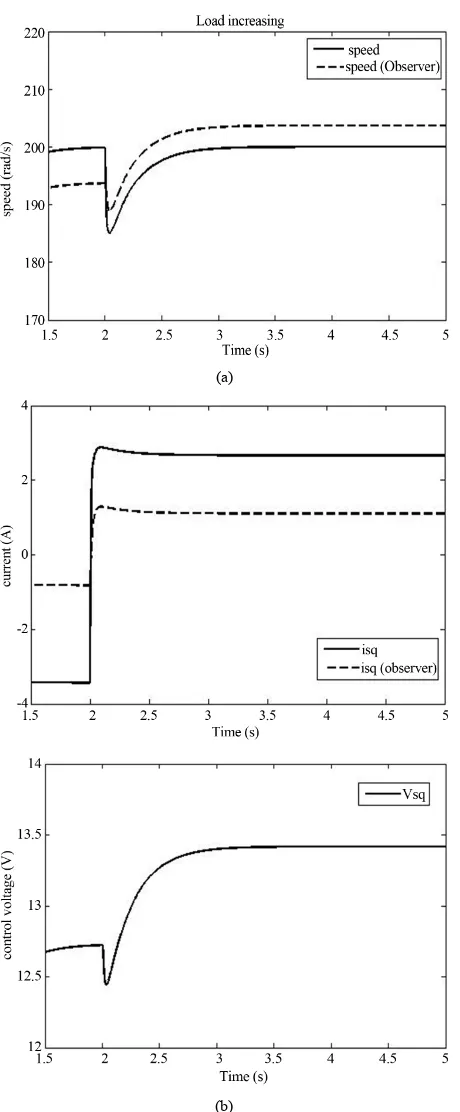
To account for the speed estimation performance of the observer acting alone and observer combined with EKF for a step change in steady state operation of PMSM,
b
condition. It is observed that the motor speed tracks the reference speed quickly and sm
(b)
(a)
(b)
Figure 7. (a) Speed response; (b) Control signal response
for the increasing lo
for observer acting alone (increase load).
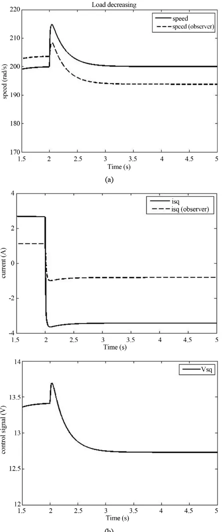
the load disturbance is applied at t = 2 s. The simulation results are shown in Figures 7 and 8
ad. Figures 9 and 10 shows the situation for the de-
creasing load.
From the obtained result, it is evident that the speed
(a)
(b)
Figure 8. (a) Speed response; (b) Control signal response for observer combined with EKF (increase load).
is combined with e EKF as compared with the case where the observer is
uction in the transient input signal varia- tio
variation caused by the load disturbance is significantly reduced in the case where the observer
th
acting alone. Also, as the simulations show, the input signal variation is reduced. The proposed approach miti- gates speed deviation caused by the load disturbance variations. Red
[image:7.595.60.290.79.635.2] [image:7.595.315.537.82.603.2](a)
(b)
Figure 9. (a) Speed response; (b) Control signal response for observer acting alone (decrease load).
and prevents the deterioration of the system performance. The simulation results are confirms the effectiveness of the proposed method.
7. Conclusion
A novel digital implementation of speed controller for a
(a)
(b)
Figure 10. (a) Speed response; (b) Control signal response or observer combined with EKF(decrease
f load).
alman Filter (EKF) is proposed. bined with EKF algorithm method at- deviation caused by the load distur- Permanent Magnet Synchronous Motor (PMSM) with disturbance rejection using conventional observer com- bined with Extended K
The observer com tenuates the speed
[image:8.595.63.286.84.616.2] [image:8.595.315.536.85.621.2]control signal is much less compared to the situation with an observer alone. The saturation of input and state is re- duced effectively and the system performance is enhan- ced significantly.
REFERENCES
[1] S. Srikanth, B. Ranganaik and M. Srinivas Rao, “S vector PWM Techniques and High Temperature Super Conducting PMSM Machines with Multilevel Inverter,” Proceedings of IEEE-International Conference on Advan-ces in Engineering, Science and Management (ICAESM), Nagapattinam, 30-31 March 2012, pp. 522-527.
[2] Y. Luo, Y. Q. Chen, H.-S. Ahn and Y. Pi, “Dy High Order Periodic Adaptive Learning Compensator f Cogging Effect in Permanent Magnet Synchronous Motor Servo System,” IET Control Theory & Applications, Vol. 5, No. 5, 2011, pp. 669-0680.
http://dx.doi.org/10.1049/iet-cta.2009.0544
pace-
namic or
[3] Y. A.-R. I. Mohamed, “Design and Implementation of Robust Current-Control Scheme for a PMSM Vector Drive with a Simple Adaptive Disturbance Observer,” IEEE Transactions on Industrial Electronics, Vol. 54, No. 4, 2007, pp. 1981-1988.
http://dx.doi.org/10.1109/TIE.2007.895074
a
[4] N. Mohan and Electric Drives, “An Integrative Ap-proach,” MNPERE, Minneapolis, 2000.
[5] P. Pillay and R. Krishnan, “Application Characteristics o Permanent Magnet Synchronous and Brushless DC Mo-tors for Servo Drives,” IEEE Transactions on Industry Applications, Vol. 27, No.5, 1991, pp. 986-996.
http://dx.doi.org/10.1109/28.90357
f
[6] N. Mohan, “Advanced Electric Drives, Analysis, Contro and Modeling Using Simulink,” MNPERE, Minneapolis 2001.
[7] L. S. Shieh, H. M. Dib and S. Ganesan, “Linear Qua Regulators with Eigenvalue Placement in a Specified Re-gion,” Automatica, Vol. 24, No. 6, 1988, pp. 819-823. http://dx.doi.org/10.1016/0005-1098(88)90058-1
l ,
dratic
[8] Y. P. Zhang, C. M. Akujuobi, W. H. Ali, C. L. Tolliver and S. Leang-san, “Load Disturbance Resistance Speed Controller Design for PMSM,” IEEE Transaction on In- dustrial Electronics, Vol. 53, No. 4, 2006, pp. 1198-1208. http://dx.doi.org/10.1109/TIE.2006.878313
[9] F. Benchabane, A. Titaouine, O. Bennis, K. Yahia and D. Taibi, “Systematic Fuzzy Sliding Mode Approach with Extended Kalman Filter for Permanent-Magnet Synchr nous Motor,” Proceedin f the IEEE international co ference on Systems Ma d Cybernetics (SMC), 2010
ens Control of IPM Motors in the Low-Speed Range and at
, o- n-gs o
n an pp. 2169-2174.
[10] S. Bolognani, S. Calligaro and R. Petrella, “S orless
Standstill by HF Injection and DFT Processing,” IEEE Transactions on Industry Applications, Vol. 47, 2011, pp. 96-104.
[11] J. lee, J. Hon and K. Nam, “Sensorless Control of Sur-face-Mount Permanent-Magnet Synchronous Motors Ba-
sed on a Nonlinear Observer,” IEEE Transactions on Power Electronics, Vol. 25, No. 2, 2010, pp. 290-297. http://dx.doi.org/10.1109/TPEL.2009.2025276 [12] Z. D. Zheng, Y
Speed and Load Torque Observer for PMSM Based on . D. Li, M. Fadel and X. Xiao, “A Rotor Extended Kalman Filter,” Proceedings of the IEEE in- ternational co Technology,
Mum-net Syn-
sing Low-Precision Shaft ctronics, Vol. nference on Industrial
bai, 15-17 December 2006, pp. 233-238.
[13] Q. T. An, L. Sun and B. Li, “Variable Parameters EKF for Speed Estimation of PMSM,” Electric Machines and Control, Vol. 11, No. 6, 2007, pp. 559-563.
[14] G. C. Zhu, L.-A. Dessaint, O. Akhrif and A. Kaddouri, “Speed Tracking Control of a Permanent-mag
chronous Motor with State and Load Torque Observer,” IEEE Transaction on Industry Electronics,Vol. 47, No. 2, 2000, pp. 346-355.
[15] T.-J. Kweon and D.-S. Hyun, “High-Performance Speed Control of Electric Machine U
Encoder,” IEEE Transactions on Power Ele 14, No. 5, 1999, pp. 838-849.
http://dx.doi.org/10.1109/63.788480
[16] A. Bado and S. Bolognani, “Effective Estimation of Speed and Rotor Position of a PM Synchronous Motor Drive by a Kalman Filte
IEEE Power Electronics Specialists Confer
ring Technique,” 23rd Annual ence, Toledo,
and A. B. Patil,
l 29 June-3 July 1992, pp. 951-957.
[17] K. Shedbalkar, A. P. Dhamangaonkar
“Speed Estimation Using Extended Kalman Filter for PMSM,” Proceedings of International Conference on Emerging Trends in Electrical Engineering and Energy Management (ICETEEEM), Chennai, 13-15 December 2012, pp. 433-435.
[18] D. Janiszewski, “Extended Kalman Filter Based Speed Sensorless PMSM Control With Load Reconstruction,” Procedings of 32nd IEEE Annual Conference on Indus- trial Electronic, IECON, 6-10 Novermber 2006, pp. 1465-1468.
[19] E. R. Kalman, “A New Approach to Linear Filtering and Prediction Problems,” Transactions of the ASME–Journa of Basic Engineering, Vol. 82, No. Series D, 1960, pp. 35-45.
[20] G. Welch and G. Bishop, “An Introduction to the Kalman Filter, Technical Report 95-041,” Department of Compu- ter Science, University of North Carolina at Chapel Hill, Chapel Hill, 1995.
[21] R. Dhaouadi, N. Mohan and L. Norum, “Design and Im- plementation of an Extended Kalman Filter for the State Estimation of a Permanent Magnet Synchronous Motor,” IEEE Transactions on Power Electronics, Vol. 6, 1991, pp. 491-49. http://dx.doi.org/10.1109/63.85891