http://dx.doi.org/10.4236/cs.2016.76052
Design and FPGA-Implementation
of Minimum PED Based K-Best
Algorithm in MIMO Detector
Poornima Ramasamy, Mahabub Basha Ahmedkhan, Mounika Rangasamy
Department of ECE, K.S.R. College of Engineering, Tiruchengode, IndiaReceived 21 March 2016; accepted 1 May 2016; published 4 May 2016
Copyright © 2016 by authors and Scientific Research Publishing Inc.
This work is licensed under the Creative Commons Attribution International License (CC BY). http://creativecommons.org/licenses/by/4.0/
Abstract
Minimum Partial Euclidean Distance (MPED) based K-best algorithm is proposed to detect the best signal for MIMO (Multiple Input Multiple Output) detector. It is based on Breadth-first search me-thod. The proposed algorithm is independent of the number of transmitting/receiving antennas and constellation size. It provides a high throughput and reduced Bit Error Rate (BER) with the performance close to Maximum Likelihood Detection (MLD) method. The main innovations are the nodes that are expanded and visited based on MPED algorithm and it keeps track of finally select-ing the best candidates at each cycle. It allows its complexity to scale linearly with the modulation order. Using Quadrature Amplitude Modulation (QAM) the complex domain input signals are modulated and are converted into wavelet packets and these packets are transmitted using Addi-tive White Gaussian Noise (AWGN) channel. Then from the number of received signals the best signal is detected using MPED based K-best algorithm. It provides the exact best node solution with reduced complexity. The pipelined VLSI architecture is the best suited for implementation because the expansion and sorting cores are data driven. The proposed method is implemented targeting Xilinx Virtex 5 device for a 4 × 4, 64-QAM system and it achieves throughput of 1.1 Gbps. The results of resource utilization are tabulated and compared with the existing algorithms.
Keywords
Multiple Input Multiple Output Detector, K-Best Algorithm, Partial Euclidean Distance, Quadrature Amplitude Modulation, Field Programmable Gate Array
1. Introduction
such as HSDPA (High Speed Download Packet Access), IEEE 802.11n [1], IEEE 802.16e and 3GPP-LTE. At receivers, MIMO signal detection plays an important role in meeting the tough requirements of real-time processing. The design of low complexity, high performance and high throughput receivers are the key chal-lenges in the design of any MIMO receiver. Several MIMO detection algorithms have been proposed to address this challenge, which offers various tradeoffs between the performance and the computational complexity.
Among the large variety of the MIMO detection techniques Maximum Likelihood (ML) detection [2] pro-vides the optimum solution with minimum BER but the computational complexity of full search grows expo-nentially as the increase in the constellation size or the number of transmitting and receiving antennas. On the other hand, linear detection algorithms such as the Successive Interference Cancellation (SIC) detectors [2] or Minimum Mean-Square Error (MMSE) detection [3] and Zero-Forcing (ZF) can greatly reduce the computa-tional complexity but at the same time they have reduced performance.
Finally to solve the trade-off between complexity and performance loss tree search algorithms are introduced. Depth-first and Breadth-first search algorithms are two main categories in tree search algorithms. In Depth-first search algorithm the tree is traversed in both forward and backward direction with variable throughput which results in extra overhead in hardware. But in Breadth-first search algorithm [4] the tree is traversed only in the forward direction with fixed throughput. A well-known approach in Breadth-first search method is the K-best algorithm [4]. The K-best algorithm guarantees a Signal to Noise Ratio (SNR)-independent fixed-throughput with a performance close to ML. In each cycle, K (Parent node) × M (Child node) children should be enume-rated, which results in large computation complexity in K-best algorithm. Here the K values are selected ran-domly. To increase the value of K, the performance result becomes close to the ML detection. However, a high-er K value results in more hardware complexity. Thus K = 10 is close to ML while having modhigh-erate complexity for a 4 × 4, 64-QAM MIMO system [5].
In this paper, to reduce the computational complexity in K-best algorithm, a MPED based K-best algorithm is designed and implemented on FPGA board (a reduced complexity systems), which making a significant reduc-tion in the over-all hardware/software complexity of the system. The K value is chosen based on the square root of constellation order of QAM. So for a 4 × 4, 64-QAM MIMO detector with K = 8 is chosen. All the results presented on system performance were first tested in Matlab and then translated into hardware blocks in Simu-link using Xilinx System Generator (SysGen). Once the hardware designs were completed, the bit streams were generated using Xilinx synthesis tools, which were required for the FPGA implementation. An efficient VLSI implementation is the key to enable real-time wireless communication.
2. MIMO System
Assume the MIMO system with Nt transmitting and Nr receiving antennas as shown in Figure 1. The equivalent baseband signal between the transmitting antenna and receiving antenna for the AWGN channel is stated in a complex-valued Nt × Nr channel matrix H [6].
The complex-valued base band received signal is expressed as,
= +
Y Hx e (1)
where x= x x1, 2,,xNtT in which Nt-dimensional complex transmitting signal vector, from which each
element is obtained independently from the complex constellation of QAM. Y = Y Y1, 2,,YNrT in which
Nr-dimensional complex received signal vector,
T 1, 2, , Nr
e e e
=
e is a complex-zero mean Gaussian noise
with the variance of σ2 per dimension. A complex domain frame work is developed here; and on the other hand for the received signal, the real value decomposition can also be derived [7].
Due to the intrinsic challenges in the implementation in the complex domain, most of the MIMO detection algorithms in the literature have been proposed for the real domain [5]. On account of the deeper search tree, the real domain implementation results in a larger silicon area and a larger latency. However, in the complex do-main a high throughput MIMO detector with an acceptable complexity for the high-order constellations has al-ways been a challenge in the literature. To address this challenge, a high throughput detection algorithm along for a 4 × 4, 64-QAM complex MIMO detector with its VLSI architecture is proposed, which is scalable to high-er ordhigh-er constellation schemes (256-QAM) and for larghigh-er numbhigh-er of transmitting and receiving antennas.
K-Best Algorithm
In K-best algorithm each level of the tree is expanded from root to the leaves and selects the best candidates with the lowest path metric that is possible in each level. The path at the last level of the tree with the lowest Partial Euclidean Distance (PED) is the hard-decision [8] output of the detector, whereas, all of the existing paths at the last level of the tree are considered to calculate shortest path node is the soft-decision [8] output of the detector. The size of the tree search grows considerably when the constellation size is increased one. There-fore, at each level of the tree an enhanced way is needed to calculate the K-best candidates without performing an exhaustive search.
The objective of the MIMO detection method is to find the closest lattice points [9] for a given received signal
2 arg min
Nt x O∈
= −
S Y Hx (2)
where O is the set of vectors from the real entries in the constellation.
The channel matrix H is QR decomposed as H = QR, where Q is the unitary Nr × Nt matrix and R is the upper triangular Nt × Nt matrix. By taking hermetian of Q or (QH), the nulling operation can be performed, which re-sults in Z = QH× Y, which in turn equals to Rx + w, where w = QH+ e, the nulling matrix is always known to be one, where the noise w after nulling remains spatially white. Since R is an upper triangular matrix in nature, hence the Equation (2) can be represented as
2 2 2 1 arg min t t Nt N N
i ij j i j i x O
z r e
= =
∈
=
∑
−∑
S (3)
the Equation (3) is considered as an tree-search problem with Nt levels, where, starting from the last row, one symbol is detected and, based on that, the next symbol in the upper row is detected, and so on.
The two computing procedures in the K-best algorithms are
1) Expansion: The K-best algorithm in the complex domain can be expressed as K (Parents of each level) ×M (Children per parent). KM children should be enumerated, which results in higher computational complexity. The relaxed K-best algorithm and base-centric search methodology [10] based on Quadrature Phase Shift Key-ing (QPSK) modulation [11] are compared [9]. These modulation schemes do not scale linearly with the con-stellation size and the performance loss that occurs in these schemes is compared to the K-best algorithm. In the on demand expansion scheme the nodes are expanded by considering all the nodes with PED, which in turn re-duces the performance for higher order constellations.
2) Sorting: In the K-best algorithm, for each level of the complex-domain, KM children should be sorted. In [12] and [13], most of the sorting schemes such as bubble sorting [14], which is sorting mechanism on the basis of Schnorr-Euchner (SE) technique [15], and a distributed sorting scheme are compared. But these techniques take high time for large values of the K and M or it will have a performance loss.
To overcome the above two challenges the MPED based K-best algorithm is proposed, in which the node with the minimum PED is considered as the parent node at each level. The computational complexity and per-formance will be better than the on-demand expansion scheme and works well for any values of K and M with-out any performance loss.
3. Proposed MPED Based K-Best Algorithm
initialized by considering the level l of the trees and assumes the candidate nodes in the level l + 1 is known in the tree. The individual nodes in the level Kl+1 will be having M possible children’s and the K value or
number of cycles will also be based on the square root of constellation order, so there will be K× M possible children in the tree.
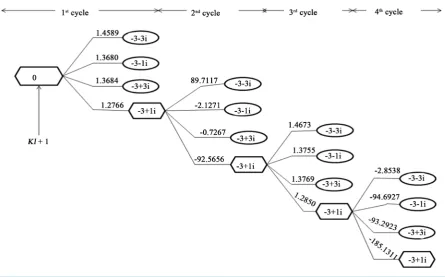
The main objective of the proposed scheme is to find the First Best Child (FBC) of the initial parent node, based on the Minimum PED of the received first M children. Assuming that initial parent node is non-nu- merical value. In other words, the key innovation behind the proposed MPED based K-best algorithm is to find the FBC of each initial parent node in the level Kl+1,and among these children the best candidate at level Kl+1, is the one which is having the minimum PED value. The best candidate selected act as a parent node for the next level. The children’s for the second level parents are generated and it replaces the first level siblings. In order to find the best path the process is repeated K times. For each level of tree the same procedure is repeated till the best path is found.
The proposed MPED based K-best algorithm scheme is diagrammatically represented in Figure 2 for level l which includes the modulation order M = 64, so the total number of levels are given by M =8, and the K = 8. It shows the way of deriving the Kl from Kl+1 level. The input to the algorithm is initially applied with zero PED value, the parent node at the level Kl+1 has four children’s, the corresponding PED values of the four children’s are shown in Figure 2.
Here the parent can find its own children’s without visiting all the nodes in the tree. Let the representation of Sl consist of best selected child for the first parent, and let PT represents the corresponding PED values (in Figure 2,
{
1}
14 3 1
S = − + i and
{
P14T =1.2766}
, where Sij represents the jth child of the ith parent node in the first lev- el of the algorithm). From Figure 2, it is noted that the child with lowest PED value is certainly the best child selected at the level 1. Similarly the above steps are followed for all the levels. Finally the best child is obtained based on the MPED based K-best algorithm.The proposed scheme involves the following features: 1) It can be easily adapted to real domain.
[image:4.595.92.538.431.708.2]2) Based on the QAM constellation size the K value is chosen in proposed scheme so as compared to the exist-ing algorithm (K value is randomly chosen) it has less computational complexity.
3) It can be applied to infinite lattices and be jointly applied with lattice reduction.
4) Increased performance is obtained by using Wavelet Packet Transformation (WPT) with the AWGN chan-nel.
5) It has reduced BER.
6) Easily implemented in VLSI architecture.
4. Proposed VLSI Architecture
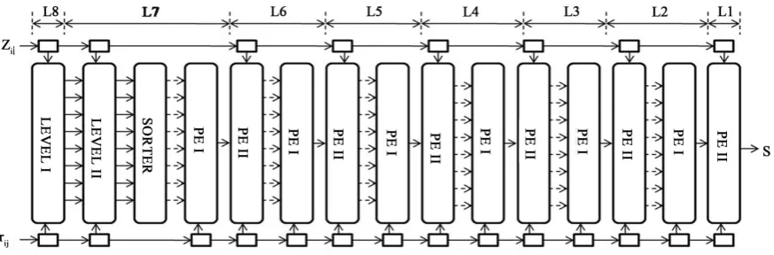
In VLSI architecture one of the main key challenges is to achieve high throughput with minimum number of le-vels that are being used in the architecture. To address this challenge, a pipelined structure is used, which per-forms the child expansion and minimization in a pipelined fashion and the sorting is implemented in a distri-buted way. The pipelined architecture involves the sorter block which sorts all the signals and the Processing Element (PE) block generates the best signal from the sorted signals.
The proposed pipelined VLSI architecture for a 4 × 4, 64-QAM hard output MIMO detector is shown in Fig-ure 3. Each layer gets the entries of zi, rij and the K parents [16] of the previous layer as inputs and generates the K parents of the next layer as outputs. The proposed architecture consists of eight layers (2Nt = 8 stages), from L1 to L8, corresponding to the 8-level detection tree.
From the MPED based K-best algorithm, the best signal is detected and this signal is taken as an input to the 8th level of the tree, which opens up all the possible values in O = {−3, −1, 1, 3}and calculates their corres-ponding PED [9]. The output of this stage is resulting in PED values, which is performed by Level I and for each of the nodes, the First Child (FC) is found and its PED value is updated using Level II.
4.1. Sorter Block
Using the Sorter block the FC is sorted and from that the child with lowest PED is determined. This is represented y Figure 3, which includes four clock cycles and all eight resulting PEDs is sorted out. The number of clock cycles required for sorting is partial than the classic bubble sort in [14]. The key idea that makes this sorter faster is the implementation of two tasks in one clock cycle through the introduction of intermediate reg-isters. The output from the sorter block is loaded simultaneously to the PE I block.
4.2. PE I Block
[image:5.595.97.534.548.692.2]The PE block contains a data register file and three computation units: an arithmetic/logic unit, a multiplier and a shifter. The PE I block takes the FC of each level as an input and generates the K-best candidate of that level one-by-one. The node with the lowest PED is definitely one of the K-best candidates in L7. This value is passed to the PE II block in L6. By removing the first child, its next sibling is calculated by the PE I block. The PED of this sibling is compared with other FCs, already present in that stage. The next K-best candidate with the lowest PED among this new set were found. This process is repeated 8 times (taking 8 cycles) until all the K-best val-ues of the second level of the tree are generated and passed to the PE II block.
4.3. PE II Block
The PE II block receives the K-best candidates of L7, one after the other, and generates the FC of each received K-best candidate one-by-one and sorts them as they arrive. It finally transfers them to its following PE I block. This process repeats for all the levels down to the first level. Since at the first level only the FC with the lowest PED is of concern, whose solution S is the hard-decision output of the detector.
5. Simulation Results
A 4 × 4 64-QAM MIMO system with K = 8 is considered in our simulation. The simulation is carried out using Matlab. The input message signal is chosen and it can be plotted in the random bit form. To apply the proposed method for the input message signal, the best candidates are identified for each cycle.
5.1. Best Candidates for the Proposed Detection Algorithm
The best candidates for the proposed MPED based K-best algorithm obtained as a result of simulation for the given input message stream are listed below.
1) The best candidate of 1 cycle is 3.283351e+003. 2) The best candidate of 2 cycle is −1.083299e+002. 3) The best candidate of 3 cycle is 3.279795e+003. 4) The best candidate of 4 cycle is −2.166598e+002. 5) The best candidate of 5 cycle is 3.393075e+003. 6) The best candidate of 6 cycle is −3.249897e+002. 7) The best candidate of 7 cycle is 3.389520e+003. 8) The best candidate of 8 cycle is −4.333195e+002.
5.2. BER Performance Analysis for Proposed Algorithm with Rayleigh and AWGN Channel
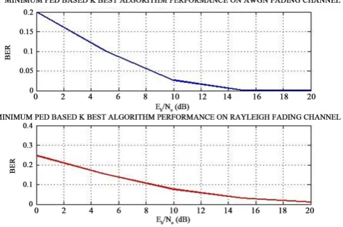
Based on BER vs. SNR the simulation results of the MIMO detections are presented in this section. BER is a key parameter that is used in assessing systems that transmit digital data from one location to another. It is defined as,BER=number of errors total number of bits sent (4)
If the medium between the transmitter and receiver is good and the signal to noise ratio is high, then the bit error rate will be very small possibly insignificant and having no noticeable effect on the overall system How-ever if noise can be detected, then there is chance that the bit error rate will need to be considered. The BER is compared with the Rayleigh fading channel as well as AWGN fading channel scheme as shown in Figure 4, with the increased SNR value from 0 to 20 dB. The analysis shows BER is less in AWGN channel with the proposed algorithm than the Rayleigh channel.
[image:6.595.192.439.532.695.2]5.3. Performance Analysis of MPED Based K-Best Algorithm
In this section we compare the proposed method (MPED based K-algorithm) with the existing MIMO detection algorithms such as ZF, MMSE-SIC and ML. The MPED based K-best algorithm gives reduced BER as com-pared to ZF and MMSE-SIC detector algorithms as shown in Figure 5. Also its result is close to ML detection method. It shows that the performance of the proposed method is close to optimum ML detection method.
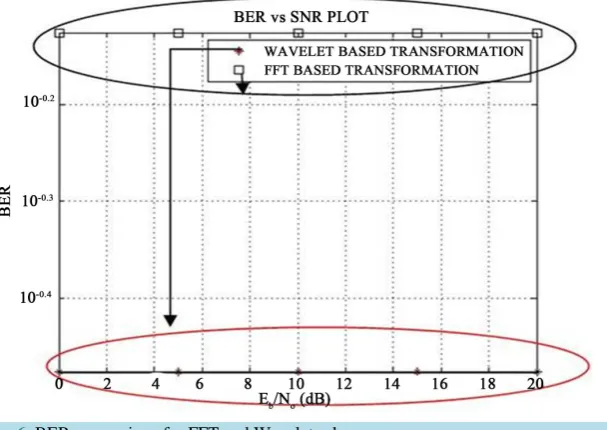
5.4. BER Comparison for FFT and WPT on Proposed Algorithm
Fast Fourier Transform (FFT) is a powerful tool for analyzing the components of a stationary signal (no change in the properties of signal). But it is less useful in analyzing non-stationary signal (change in the properties of signal). Wavelet Packet Transforms allows the components of both stationary and non-stationary signals to be analyzed. The main difference is that wavelets are well localized in both time and frequency domain whereas the Fourier transform is only localized in frequency domain. The BER is compared for both FFT as well as WPT [11] as shown in Figure 6. From the figure the Wavelet scheme produces a less BER irrespective of the SNR, than the FFT scheme. So WPT transformation technique is used in our proposed method for processing the sig-nal.
6. Complexity Analysis
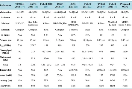
The proposed complex MIMO detector and the recently proposed MIMO detectors in the real and complex do-mains which were compared and reported in the literature is shown in Table 1. This comparison suggests that the proposed scheme has the high performance i.e., higher throughput, lower area, lower energy and lower la-tency compared to all the reported real and complex-domain VLSI realizations.
[image:7.595.96.538.427.724.2]This design has a larger core area than the one in [9], which is related to the nature of the complex-domain implementation and extra resources for the complex-domain calculations. Thus the major difference between all of these schemes, including the one in this paper, is the way the detection algorithm is implemented, which translates to different throughput and hardware complexity. It is shown that the proposed algorithm is imple-
Table 1. Design comparison of the current VLSI implementations for 4 × 4 MIMO detectors.
References TCAS-II 2010 [17]
DATE 2009 [18]
TVLSI 2010
[19]
JSSC 2010 [20]
JSSC 2011 [21]
TVLSI 2011 [22]
TVLSI 2011 [9]
TVLSI 2013 [5]
Proposed Work
Modulation 16-QAM 64-QAM 64-QAM (4-64) QAM 64-QAM (16-64) QAM 64-QAM 64-QAM 64-QAM
Antenna 4 × 4 4 × 4 4 × 4 4 × 4 - 8x8 4 × 4 4 × 4 4 × 4 4 × 4 4 × 4
Method SISO-SD Detection Sys. Like K-Best MBF-FD(SD) MMSE PIC SISO MMF-LSD K-Best Modified K-Best based K-Best MPED
Domain Complex Complex Real Complex Complex Real Real Complex Complex
K-value N/A N/A 5-64 N/A N/A N/A 10 10 8
Process size 90 nm 45 nm 65 nm 0.13 µm 90 nm 0.18 µm 0.13 µm 0.13 µm 0.13 µm
fmax (MHz) 250 574.7 158 198 568 250 282 417 435
Throughput
(Mb/s) 90 215 732 - 100 285 - 431 757 31.7 - 146.3 675 1000 1100
Gate count
(kG) 96 33.1 1760 350 410 25.4 - 48.2 114 340 328
NHE 1.6 0.45 4.81 - 35.2 1.23 - 0.81 0.78 0.58 - 0.24 0.17 0.34 0.3
Energy/bit N/A N/A N/A N/A 250 PJ/b N/A 200 pJ/b 110 pJ/b 100 pJ/b
Power (mW) N/A N/A 165 57-74 189.1 57-90 135 1700 1684
Latency (µs) N/A N/A N/A N/A N/A N/A 0.6 0.36 0.27
Figure 5. Analysis of MPED based K-best algorithm with various detection algorithm.
Figure 6. BER comparison for FFT and Wavelet scheme.
mented using a feed forward architecture. According to the proposed algorithm, K-best candidates of each layer of the architecture are generated in Kclock cycles, which increase the throughput of the system.
The throughput of the system is the number of packets produced per unit time. This is measured in units of whatever is being produced (I/O samples, memory words, iterations) per unit time. The latency is the number of cycles required for the system to accept next input and the gate count involves the total core area of the design.
The Normalized Hardware Efficiency (NHE) is calculated, which is given by the gate count and the corres-ponding scaled throughput [5] in the same technology for all designs. So
(
)
core area kG( )
(
)
NHE kG Mb ps
scaled throughput Mb s
= (5)
Moreover, the proposed scheme is implemented in the FPGA platform. The synthesis results and the required resources for the 4 × 4, 64-QAM MIMO detector using the proposed scheme is shown in Table 1.
7. Conclusion
[image:8.595.166.470.297.512.2]pro-posed. This proposed algorithm is scalable both in terms of number of transmitting/receiving antennas and the constellation size. It gives a reduced BER and low computational complexity as compared to existing algorithms. This is carried out by simulating both in terms of FFT scheme and wavelet scheme using Matlab. The proposed design was implemented in Virtex-5 FPGA from Xilinx platform; it provides a high throughput of 1.1 Gigabits per second (Gb/s) at 435 MHz with the area of 328 K gates in a 0.13-µm VLSI process. This algorithm is appli-cable for real time wireless communication.
References
[1] Bansode, R.S. and Borole, P. (2013) Hardware Implementation of an OFDM Transceiver for 802.11n Systems. Inter-national Journal of Scientific & Engineering Research, 4, 1530-1540.
http://www.ijser.org/researchpaper/hardware-implementation-of-an-ofdm-transceiver-for-80211n-systems.pdf
[2] Wubben, D., Bohnke, R., Kuhn, V. and Kammeyer, K.-D. (2004) Near-Maximum Likelihood Detection of MIMO Systems Using MMSE-Based Lattice-Reduction. IEEE International Conference on Communication, Vol. 2, 2798- 2802. http://dx.doi.org/10.1109/icc.2004.1312611
[3] Wubben, D., Bohnke, R., Kuhn, V. and Kammeyer, K.D. (2004) MMSE-Based Lattice-Reduction for Near-ML Detec-tion of MIMO Systems. IEEE International Conference on Antenna,18-19 March 2004, 106-113.
http://dx.doi.org/10.1109/wsa.2004.1407656
[4] Chen, S.Z., Zhang, T. and Xin, Y. (2005) Breadth-First Tree Search MIMO Signal Detector Design and VLSI Imple-mentation. Military Communications Conference (MILCOM 2005), Vol. 3, 1470-1476.
[5] Mahdavi, M. and Shabany, M. (2013) Novel MIMO Detection Algorithm for High-Order Constellations in the Com-plex Domain. IEEE Transactions on Very Large Scale Integration (VLSI) Systems, 21, 834-847.
[6] Lin, H.-L., Chang, R.C., and Chen, H.-L. (2008) A High-Speed SDM-MIMO Decoder Using Efficient Candidate Searching for Wireless Communication. IEEE Transactions on Circuits and Systems II: Express Briefs, 55, 289-293. http://dx.doi.org/10.1109/TCSII.2008.918973
[7] Guo, Z. and Nilsson, P. (2006) Algorithm and Implementation of the K-Best Sphere Decoding for MIMO Detection.
IEEE Journal on Selected Areas in Communications, 24, 491-503. http://dx.doi.org/10.1109/JSAC.2005.862402 [8] Shen, C.A., Eltawil, A.M., Salama, K.N. and Mondal, S. (2011) A Best-First Soft/Hard Decision Tree Searching
MIMO Decoder for a 4 × 4 64-QAM System. IEEE Transactions on Very Large Scale Integration (VLSI) Systems, 20, 1537-1541.
[9] Shabany, M. and Gulak, P.G. (2012) A 675 Mbps, 4 × 4, 64-QAM K-Best MIMO Detector in 0.13 µm CMOS. IEEE Transactions on Very Large Scale Integration (VLSI) Systems, 20, 135-147.
http://dx.doi.org/10.1109/TVLSI.2010.2090367
[10] Lin, H.-L., Chang, R.C. and Chan, H. (2008) A High-Speed SDM-MIMO Decoder Using Efficient Candidate Search-ing for Wireless Communication. IEEE Transactions on Circuits and Systems II: Express Briefs, 5, 289-293.
[11] Chen, S., Zhang, T. and Xin, Y. (2007) Relaxed K-Best MIMO Signal Detector Design and VLSI Implementation.
IEEE Transactions on Very Large Scale Integration (VLSI) Systems, 15, 328-337. http://dx.doi.org/10.1109/TVLSI.2007.893621
[12] Trivedi, S., Raeen, M.S. and Pawar, S.S. (2012) BER Analysis of MIMO-OFDM System Using BPSK Modulation Scheme. International Journal of Advanced Computer Research, 2, 208-214.
[13] Bingham, J.A.C. (1990) Multicarrier Modulation for Data Transmission: An Idea Whose Time Has Come. IEEE Communications Magazine, 28, 5-14. http://dx.doi.org/10.1109/35.54342
[14] Wong, K.W., Tsui, C.Y., Cheng, R.S.K. and Mow, W.H. (2002) A VLSI Architecture of a K-Best Lattice Decoding Algorithm for MIMO Channels. IEEE International Symposium on Circuits and Systems, 3, 273-276.
[15] Guo, Z. and Nilsson, P. (2004) Reduced Complexity Schnorr-Euchner Decoding Algorithms for MIMO Systems. IEEE Communications Letters, 8, 286-288. http://dx.doi.org/10.1109/LCOMM.2004.827376
[16] Smolyakov, V., Patel, D., Shabany, M. and Gulak, P.G. (2010) A WiMAX/LTE Compliant FPGA Implementation of a High-Throughput Low-Complexity 4×4 64-QAM Soft MIMO Receiver. 2010 Conference Record of the 44th Asilomar Conference on Signals, Systems and Computers (ASILOMAR),Pacific Grove,7-10 November 2010, 385-389. http://dx.doi.org/10.1109/ACSSC.2010.5757541
[17] Witte, E.M., Borlenghi, F., Ascheid, G., Leupers, R. and Meyr, H. (2010) A Scalable VLSI Architecture for Soft-Input Soft-Output Single Tree-Search Sphere Decoding. IEEE Transactions on Circuits and Systems II: Express Briefs, 57, 706-710. http://dx.doi.org/10.1109/TCSII.2010.2056014
870-873. http://dx.doi.org/10.1109/date.2009.5090784
[19] Mondal, S., Eltawil, A., Shen, C. and Salama, K. (2010) Design and Implementation of a Sort-Free K-Best Sphere De-coder. IEEE Transactions on Very Large Scale Integration (VLSI) Systems, 18, 1497-1501.
http://dx.doi.org/10.1109/TVLSI.2009.2025168
[20] Kim, B. and Park, I.C. (2008) K-Best MIMO Detection Based on Interleaving of Distributed Sorting. Electronics Let-ters, 44, 42-43. http://dx.doi.org/10.1049/el:20082129
[21] Wenk, M., Zellweger, M., Burg, A., Felber, N. and Fichtner, W. (2006) K-Best MIMO Detection VLSI Architectures Achieving up to 424 Mb/s. IEEE International Symposium on Circuits and Systems,Kos, 21-24 May 2006, 1151-1154.
[22] Myllyl, M., Cavallaro, J. and Juntti, M. (2011) Architecture Design and Implementation of the Metric First List Sphere Detector Algorithm. IEEE Transactions on Very Large Scale Integration (VLSI) Systems, 19, 895-899.