Published Online November 2013 (http://www.scirp.org/journal/epe) http://dx.doi.org/10.4236/epe.2013.59058
Towards Economic Single-Phase Motor
Mahdi Alshamasin
Faculty of Engineering Technology, Al-Balqa’ Applied University, Amman, Jordan Email: [email protected]
Received September 6,2013; revised October 6, 2013; accepted October 13, 2013
Copyright © 2013 Mahdi Alshamasin. This is an open access article distributed under the Creative Commons Attribution License, which permits unrestricted use, distribution, and reproduction in any medium, provided the original work is properly cited.
ABSTRACT
Studying of operation balance in single-phase induction motors is an issue of interest due to the need for reducing the power consumption and increasing the motors’ life. The paper focuses on improving the motor performance by balanc- ing the stator phase operation for the most common-used connection diagrams of single-phase capacitor-run induction motors (SPCRIMs) and three-phase induction motors (TPIMs) operating from single-phase supply (SPS). Therefore, a mathematical model is used to balance the motor operation by varying the frequency supply voltage. Characteristics of balancing parameters are investigated, various methods of motor balancing are presented and comparisons were done among these balancing methods.
Keywords: Performance of Capacitor-Run Motor; Main Phase; Balanced Operation; Symmetry; Connection Circuit Diagrams; Control of Balancing Parameters; Reactive Elements; Power Factor; Efficiency
1. Introduction
Economic single phase motors are required nowadays since a huge amount of power is consumed due to the wi- de using of these motors in the life fields such as: domes- tic, agricultural, industrial fields and so on [1-3].
By improving the performance of single-phase motors, farms, petroleum wells, homes and faraway workshops having only a single-phase line do not need to install ex- pensive three-phase lines or resort to expensive inverters or diesel pumps. Also, in many applications, it may be necessary to use a three-phase induction motor on a sin- gle-phase supply system. For example, technical and economic advantages have been found to initially install a single wire earth Return (SWER) system for rural elec-trification in remote and hilly regions [4].
For single-phase capacitor-run induction motor (SPCRIM) and three-phase induction motor (TPIM) operating from single-phase supply (SPS), full-load current may have almost unity power factor which reduces the power com- pany transformers and distribution losses. At balanced motor operation, the efficiency of single-phase motors may exceed 90 percent. Thus, single-phase motor per- formance can be improved and become competitive to that of three-phase motor on a three-phase line. Using the SPCRIMs is the best choice to compete the three-phase motors; whereas the run capacitor can improve the motor efficiency, the starting torque and the power factor. Also,
using of additional reactive elements leads to robust mo- tor balancing to ensure the excellent performance of the motor [5].
As a matter of fact, SPCRIM and TPIM fed from SPS suffer from heating due to the elliptical field caused by asymmetry of phase loads [6]. The non-uniform opera- tion of stator phases of these motors is negatively re- flected on the winding temperature, the power factor and the efficiency of the motor [7,8]. Therefore, the elimina- tion of the asymmetric action is of a great theoretical and practical significance.
The conventional connection diagrams of SPCRIMs and TPIMs operating from SPS [9,10] using a constant capacitance value in a stator circuit supplied by constant frequency voltage, are not capable to provide balanced operation of stator phase in the whole range of motor slip [11]. This is due to the ellipticity of a rotating field, which takes a circular form only under certain conditions. In this case, balancing is possible only at a certain value of slip and load fluctuations will cause the unbalancing of the motor and produce heating in the motor windings [12]. Eliminating the asymmetry of phase loads is possi- ble by using the following methods:
1) Using one value phase-shifting capacitor and regu- lating the frequency of the power supply.
M. ALSHAMASIN 529
the most suitable method to provide the required values of phase currents and appropriate angles between them (rigorous symmetry).
3) Switching a number of stator winding turns and re- gulating the value of phase-shifting capacitance [13,14], which is regarded as the most economical method from the point of view of electrical energy utilization and mo- tor heating. This paper develops a mathematical model to balance the motor operation by varying the frequency of supply voltage and investigating the characteristics of the balancing parameters. Also, the paper presents advanced review for the used methods of balancing, comparison among them through behavior investigation and limita- tions of each method for the most used connection dia- grams of induction motors fed from single-phase supply in practical applications.
2. Balancing of the Motor Operation by
Controlling the Supply Frequency
The produced field in the SPCRIM and TPIM operating from SPS can have a rectilinear, an elliptical or a circular form, depending on the reactance of the phase-shifting capacitor. Of course, the machine will have the best effi-ciency and power factor when the field has a circular form. Thus, phase currents are equal in magnitude and the phase angle between them is 90 electrical degrees at SPCRIMs or 120 electrical degrees at TPIM operating from SPS. The reactance can be controlled by varying the frequency of the supply voltage and under certain conditions at which negative sequence current
I2becomes zero the motor operation is balanced [15]. The capacitor reactance value that satisfies the first balancing condition can be calculated from the following relation:
1
K
X BX (1)
the second balancing condition is:
1
R AX1 (2)
where A and B are the balancing coefficients
2.1. Balancing Conditions of SPCRMs with Two Windings Connected in Parallel
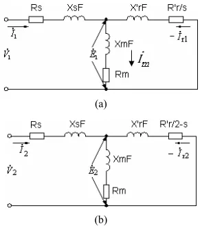
[image:2.595.355.494.85.194.2] [image:2.595.350.497.234.398.2]Circuit diagram of SPCRIM with two windings connect- ed in parallel is shown in Figure 1. Utilizing the sym- metrical components methods, the unbalanced motor va- riables can be decomposed into positive (forward) sequen- ce and negative (backward) sequence components [16,17].
Figure 2 shows the equivalent circuit of these compo- nents [18].
According to the symmetrical components method, the phase currents can be written as [16,19]
1 2
A
[image:2.595.305.542.470.714.2]I I I (3)
Figure 1. Circuit diagram of SPCRM with two windings connected in parallel.
(a)
(b)
Figure 2. Per-phase equivalent circuit; (a) Positive sequence, (b) Negative sequence.
1
m
I jKI jKI2 (4)
From Kirchhoff's Law, the voltages that model the SPCRM are
1 1 2 2
1 2 1
1 2 2 2 1 2
m m m m m m m
V V I Z I Z I Z
2
Z Z Z
jkI jkI jI jI
k k
k k
Z
(5)
1 1 2 2 1 2
1 1 2 2
A A K A A A K
k
k k
V V I Z I Z I Z
I Z I Z I I Z
I Z Z I Z Z
(6)
where
1 2
1 2 2 2 A
m
Z Z Z
Z Z
Z
k k
From Equations (5) and (6), the balance equation (at which I2 becomes zero) is
1
1 k 0
Z
j Z Z
k
(7)
imped-ances then gives
1 1
1 k 0
R jX
j R jX jX
k
(8)Solving this equation yields
1 1
1 0
R X
K
(9)
1
1 k 0
R
X X
k
(10)
From Equations (9) and (10), we get
1 1 1 R X K and 1 1 1 2 2 1 1 K X
X X X
k k
Thus, the balance coefficients are
1 A K and 2 1 1 B K
2.2. Balancing Conditions of Three-Phase Induction Motor Fed From Single-Phase Supply
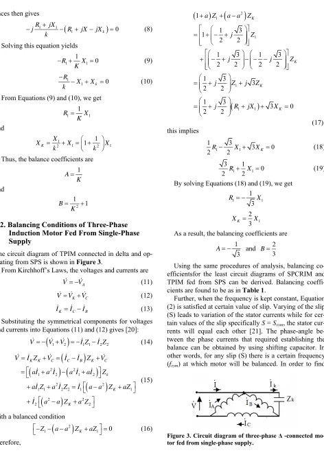
The circuit diagram of TPIM connected in delta and op- erating from SPS is shown in Figure 3.
From Kirchhoff’s Laws, the voltages and currents are
A
V V (11)
K C
VV V (12)
K C
I I IB
2
1
(13) Substituting the symmetrical components for voltages and currents into Equations (11) and (12) gives [20]:
1 2
1 1 2V V V I Z I Z (14)
2 2
1 2 1 2
2 2
1 1 2 2 1 1
2 2
2 2
K K C C B K C
k
K
K
V I Z V I I Z V
aI a I a I aI Z
aI Z a I Z I a a Z aZ
I a a Z a Z
(15)
with a balanced condition
2
1 K 0
Z a a Z aZ
(16)
therefore,
2 1 1 1 1 1 1 1 3 1 2 21 3 1 3
2 2 2 2
1 3 3
2 2 1 3 3 0 2 2 K K K K
a Z a a Z
j Z
j j
j Z j Z
j R jX X
Z (17) this implies 1 1 1 3 3
2R 2 X XK 0 (18)
1 1
3 1
0
2 R 2X (19)
By solving Equations (18) and (19), we get
1 1
1 3
R X
1 2 3 K
X X
As a result, the balancing coefficients are 1
3
A and 2
3
B
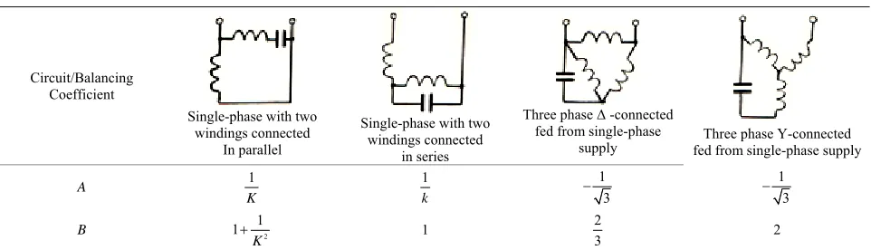
Using the same procedures of analysis, balancing co-efficientsfor the least circuit diagrams of SPCRIM and TPIM fed from SPS can be derived. Balancing coeffi-cients are found to be as in Table 1.
Further, when the frequency is kept constant, Equation (2) is satisfied at certain value of slip. Varying of the slip (S) leads to variation of the stator currents while for cer-tain values of the slip specifically S = Ssym, the stator
[image:3.595.65.537.72.738.2]cur-rents will equal each other [21]. The phase-angle be-tween the phase currents that required establishing the balance can be obtained by using shifting capacitor. In other words, for any slip (S) there is a certain frequency (fsym) at which motor will be balanced. In order to find
Figure 3. Circuit diagram of three-phase Δ -connected mo-or fed from single-phase supply.
M. ALSHAMASIN 531
Table 1. Balancing coefficients for the common used connection circuits.
Three phase Ү-connected fed from single-phase supply Three phase Δ -connected
fed from single-phase supply Single-phase with two
windings connected in series Single-phase with two
windings connected Circuit/Balancing Coefficient In parallel 1 3 1 3 1 k 1 K A 2 2 3 1 2 1 1 K B
the freque at which a balanced op n of the motor eved for different values of slip, the value f R1 and X1
ust be found from the equivalent circuit of single phase motor in ncy eratio is achi Figure 2(a) as s o m
2
r r r
m m m r m r
R R R
R R X X F X F X F R
1 2 2
2 2
m r m
s
r r
m m r m m r
X F X F
s s
s
R R
R R
R X F X F R X F X F
s s (20)
21 2 2
2 2
r r r
m m r m m r m m r
s
r r
m m r m m r
R R R
R R X F X F X F X F R X X F
s s s
X X F
R R
R X F X F R X F X F
s s
(21)
Substituting R1 and X1 from Equation (20) and Equation (21) into Equation (2) and rearranging the obtained equation
with neglecting of stator active resistance, the per-unit balancing frequency sym n F f f
can be found as:
4
2 R X 4 (A X X X X X X
X
R )( )
2 2
r m s m r m s r m r m
m r
m r s r m r m m r s r m r m
X X X
F
s A X X X X X X X As X X X X X X X
(22)
For low and medium power motors, one may considerXr XS, and then the per-unit balancing frequency
calculated as: can be
2 2 2 4X X X X
R
2 4
2
m m r m r
r
m r r
A X F
s A X X X
(23)
when the frequency value is given, the slip at which the motor operation is balanced can be derived as:
2 4 4
m m s m r m s r m r m
r sym
X X A X X X X X X X X X
R S
2 m r s r m r m
F A X X X X X X X
(24)
The critical slip (slip at maximum torque) is a function f frequency and can be calculated from the expression [2
o 2]
2 2r cr
s s r
R S
R FX FX
(25)
3. Balancing the SPCRIM by Inserting an
Inductive Reactance into the Stator
Circuit
The values of the balancing impedance
by the following group of equations [5]:
2 2
K L
a Z a Z
X 1 1 ;X 2 1 (26)
1 1 1 1 2 1 2 1
b R d X b R d X
3 1 3 1; 4 1 4 1
K L
X a R b X X a R b X (27)
where, the coefficients of Equations (26) and (27) can be obtained from Table 2.
4. Balancing the Motor Operation by
Controlling the Capacitance Value
In this method, the frequency is constant and f
y the balance operation when the load is changing. The balancing capacitor value can be
g capacitance value can be calculated from the Equations (5) and (6) by equating requently is equal to the nominal frequency whereas the capaci- tance is varying to satisf
controlled electronically [4,23].
Balancing of SPCRM with Two Windings Connected in Parallel
For the SPCRIM with two windings connected in parallel where the capacitor value is varying in respect with the load as in Figure 4, the balancin
the absolute values of IA and IB as [10,24].
6 2a 10
2 ,
100 4
C F
b b ad
(28)
where
2 3 2
1 2
4 4
a H b H R H X X
2 1
2 2
4 3
2 1 2 1 2
2 2
1 2 2 1 1 2 1 2
4 4
4
A
m
R
d H R R X X H R X R X
H R X R X R R X X
N
5. Simulation and Results
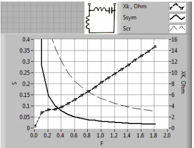
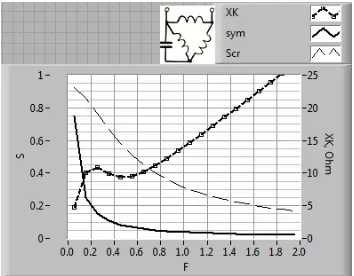
Curves of balancing parameters XK, Ssym and Scrversus
fre-quency ,depending on the Equations (1) , (24) and (25), were investigated by using labVIEW software for the SPCRIM and TIM operating from SPS with the following data:
Figures 5-8 show the obtained curves for the most used connection diagrams.
It can be seen from these figures that Ssym is inversely
proportional to the frequency, where its value at low fre- quencies approaches 1. This means that the motor can be started with a balanced status and this is considered a very important aspect in the intermittent periodically duty motors. However, at steady-state operation, the low frequency could cause a great loss in energy because of the high value of balancing slip, and this should be av
cr
1 1 2
1
H
K N
2.8 , 156 ,
n n
P kw V V
50 , 0.04, 950 , 0.92 ,
n t
f Hz
S N rpm R
0.58 , 1.1 , 2.12 , 2.12 21 .
n n s
m st
r r
m
R X
X X
R
1kw, 220 / 380V, 50Hz,
P V f
0.05, 2850rpm, 7.5 ,
7 , 29.5 , 10.5 ,
10.5 , 196.5 .
n n n
n n st
m st
r m
r
S N R
R X
X X
R
oided. The doted curves give the variations of critical slip versus frequency. It should be noted that as long as
S > Ssym, the motor will be stable and the stability will
depend on the difference between Scr and Ssym where the
greater the difference the more stable the motor. There-fore, the steady-state region is defined when f > 0.2 fn.
The impedance characteristics of the balancing ele- ments are also built by using a labVIEW software.
Figure 9 shows the relation between the balancing im- pedance and the slip at different frequencies for the abo- ve described motors with the attached connection dia- grams:
The values of reactance are calculated by using Equa- tions (26) and (27) for Figures 9(a) and (b), respectively.
Figure 9(a) shows that the inductive reactance XL is high
at no-load condition, and decreases by increasing the load till it reaches a minimum value without crossing the
[image:5.595.350.498.436.517.2]X-axis (only inductive behavior. This is clear for high
Figure 4. Single-phase induction motor with two windings connected in parallel and electronically controlled capaci-
or. t
[image:5.595.329.519.564.709.2]M. ALSHAMASIN 533
Table 2. Coefficients of balancing equations for common types of circuit diagrams.
a1 1 _ 1 _ 1 _ 3 _
a2 1 _ 1 _ 1 _ 3 _
a3 _ 1/k _ 1/k _
1
_ 3
3
a4 _ 1/k _ 1/k _
1 3
_ 3
b1 k _ k _ 3 _ 3 _
b2 k _ k _ 3 _ 3 _
b3 _ 1 _ 0 _ 1
3 _ 1
1 _
b4 _ /k2 1 _ 1
3 _ 1
d1 0 _ 1 _ 1 _ 1 _
d2 1 _ k2 _ 1 _ 1 _
Figure 8. Balance of Ү—connected TPIM three-phase in- duction motor fed from single-phase supply.
frequencies of the supply voltages. The balancing capaci-tive reactance XK is high at no-load condition and
de-creases with increasing the load in the same way for all the frequencies of the supply voltages.
Figure 9(b) shows that both the balancing reactance
XL and reactance XK have the same behavior. At first,
they increase by increasing the load until they reach maximum values, then they begin to decrease again. Balancing inductive reactance X will cross the -axis
g the supply voltage frequency, the crossing point of the XL with the X-axis
[image:6.595.84.261.569.707.2]will occur at lower values of the slip. It is clear that at high frequencies, the balanced operation will be achieved
Figure 6. Balance of SPCRIM with two windings connected in series.
L
(capacitive behavior) at the frequency f = 40 Hz (F = 0.8)
and a high slip value. By increasin
X
(a)
[image:7.595.325.521.85.254.2](b)
Figure 9. Impedance characteristics; (a) auxiliary winding is shunting by inductive element, (b) Inductive element is inserted in series with the main winding.
by regulating the capacitance value only, in other words, both balancing elements should be capacitors.
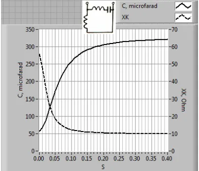
The same inductive and capacitive behaviors are oc-curred for the least of connection diagrams, listed in the
Table 2, based on the group of Equations (26) and (27 The balancing capacitan haracteristic was built us-ing Equation (28) also for the motor of power Pn = 2.8 kw
as shown in Figure 10.
This figure shows that for constant frequency f = fn, the
balancing capacitance value is proportional to the slip until specified value then the relation becomes nonlinear and the balancing capacitance almost hasn’t considerable change as slip increases over the critical slip. The bal-
). ce c
Figure 10. Balancing capacitance of single-phase capacitor- rum induction motor versus slip.
ancing capacitance for the start condition is much larger
nts especially in
Th
tion motor is widely used in en- gi
operation by varying the frequency of supply voltage and investigating the characteristics of the balancing parame- ters. The proper selection of reactive element will im-prove the single-phase induction motor performance to compete the three-phase motor.
The advantages of the balancing method by changing the frequency are:
1) Wide range of speed control.
2) Soft speed control and improvement of starting characteristics.
3) This method can be used for various power rating motors with any stator circuit connection.
The disadvantages of this method are:
4) Steady state motor operation at low freque ies than for the run condition. Although increasing the ca- pacitance over the nominal value helps in balancing but it
s accompanied by increasing the curre i
the auxiliary winding .Therefore, this method is promis- ing for the variations of load around the nominal value if the motor duty is continuous.
6. Conclusions
e study discusses the various methods to improve the performance of SPCRIMs and TPIMs operating from SPS. Single-phase induc
neering practice and spends a lot of electricity each year. The promotion of induction motor’s efficiency has great significance for energy consumption, so the opti- mization design of single-phase induction motor is nec- essary. The mathematical model seems to be well.
The mathematical model is used to balance the motor
nc (F < 0.2) is forbidden due to the small maximum to the
nominal torque ratio.
[image:7.595.68.278.85.527.2]M. ALSHAMASIN 535
Balancing by varying capacitance value of the conden- ser at constant frequency is the most economic especially if it is realized by electronic way but this method is not fair as the slip goes far from the nominal value.
For having robust balancing, in addition to the shifting phase capacitor, reactive elem
the stator circuit. This method
ent should be inserted into will reduce the heat gener- ring the steady state operation mode speed control. Thus, the benefits of
egard- le
masin from Al-B A
bers of Switches,” IEEE Transactions
ated in the motor du for the full range of
this method include improved power factor, energy sav- ing and elimination of the need for additional winding taps for speed variation.
According to the generalized calculation equations for balancing element impedance, the connection balancing diagrams could be grouped into two groups. For the first group of connection diagrams, the behavior of the bal- ancing element is inductive over the whole slip r
ss of the value of the voltage frequency. While for the second group of connection diagrams, the behavior of the balancing impedance XL will become capacitive depend-
ing on the load and the voltage frequency.
7. Acknowledgements
This work has been carried out during sabbatical leave granted to the author Mahdi Alsha alqa’ pplied University (BAU)-Jordan during the academic year 2012/2013. I’d like to thank Al-Balqa’ Applied University for their support and Najran University-KSA for their logistic aid.
REFERENCES
[1] M. Chomat, “Adjustable-Speed Single-Phase IM Drive with Reduced Num
on Industry Application, Vol. 39, No. 3, 2003, pp. 819- 826. http://dx.doi.org/10.1109/TIA.2003.811778
[2] K. Sundareswaran, N. Rajasekar and V. Sreedevi, “Per-formance Comparison of Capacitor-Run Induction Mo-tors Supplied from AC Voltage Regulator and SPWM AC Chopper,” IEEE Transactions on Industrial Electronics, Vol. 53, No. 3, 2006, pp. 990-993.
http://dx.doi.org/10.1109/TIE.2006.874256
[3] E. Muljadi, Y. Zhao, T. Liu and A. T. Lipo, “Adjustable ac Capacitor for a Single-Phase Induction Motor,” IEEE Transactions on Industry Applications, Vol. 29, No 3, 1993, pp. 479-485.http://dx.doi.org/10.1109/28.222415 [4] M. Alshamasin, “Control of Zero-Sequence Braking for a
Three-Phase Induction Motor Operating from Single- Phase Supply with a Controlled Capacitor,” Journal of Applied Sciences, Vol. 12, No 24, 2012, pp. 2616-2620. http://dx.doi.org/10.3923/jas.2012.2616.2620
[5] M. S. Alshamasin, “Balancing the Operation of Stator Phases of the Capacitor-Run Single-Phase Induction Mo- tors at Variable Frequencies,” Journal of Engineering, Vol. 14, No. 3, 2004, pp.173-180.
teractive Software for the Analysis of Thermal Character- istics of Capacitor-Run Single-Phase Induction Motors,” Electric Power Components and Systems, Vol. 29, No. 11, 2001, pp. 997-1011.
[6] S. K. Chowdhury, S. P. Chowdhury and K. Pal, “An
In-53250001753239211 http://dx.doi.org/10.1080/1
of the Performance of [7] M. Alshamasin, “Optimization
Single-Phase Capacitor-Run Motor,” American Journal of Applied Sciences, Vol. 6, No. 4, 2009, pp. 745-751. http://dx.doi.org/10.3844/ajassp.2009.745.751
[8] G. Singh, “A Research Survey of Induction Motor Opera- tion with Non-Sinusoidal Supply Wave Forms,” Electric Power Systems Research, Vol. 75, No. 2-3, 2005, pp. 200-213. http://dx.doi.org/10.1016/j.epsr.2005.04.001 [9] T. A. Letenmaier, D. W. Novotny and T. A. Lipo,
“Sin-gle-Phase Ind lectronically
Con-trolled Capacito on Industry Appli-uction Motor with an E
r,” IEEE Transactions cations, Vol. 27, No. 1, 1991, pp. 38-43. http://dx.doi.org/10.1109/28.67530
[10] N. M. Ocmanhodjaiev, M. S. Alshamasin and N. Laieb, “About Equilibrium of Stator-Load Currents of Single-
al of applied Phase Capacitor Asynchronous Motors,” Problems of In- formatics and Energy, No. 4, 1997, pp. 18-20.
[11] M. B. Senan, I. Aris and S. H. Hamad, “Development of Single Phase Induction Motor Adjustable Speed Control Using M68C11E-9 Microcontroller,” Journ
sciences, Vol. 5, No. 2, pp. 259-252.
[12] L. H. Liu, M. T. Lin and H. C. Wu, “A Single Phase In- duction Motor Drive with Improved Performance,” Elec- tric Power System Research, Vol. 47, No. 1, 1998, pp. 29-38.http://dx.doi.org/10.1016/S0378-7796(98)00036-4 [13] M. A. Abelhaleem, “Control of Single Phase Induction Motor Using Forced-Commutated Electronic Switches and Free-Wheeling Paths,” Electric Machines and Power Systems Journal, Vol. 27, No. 11, 1999, pp. 1201-1214.
http://dx.doi.org/10.1080/073135699268669
[14] G. S. Ilango, K. Samidurai, M. Roykumar and K. Tha- nushkodi, “Energy Efficient Power Electronic Controller for a Cpacitor-Run Single-Phase Induction Motor,” En-ergy Conversion and Management, Vol. 50, No. 9, 2009, pp. 2152-2157.
http://dx.doi.org/10.1016/j.enconman.2009.04.024 [15] S. Williamson and A. C. Smith, “A Unified Approach to
the Analysis of Single-Phase Induction Motors,” IEEE Transactions on Industry Applications, Vol. 35 1999, pp. 837-843.
, No. 4,
, .485829 [16] S. D. Umans, “Steady-State, Lumped-Parameter Model
for Capacitor-Run Single-Phase Induction Motors,” IEEE Transactions on Industry Applications, Vol. 32, No. 1 1996, pp. 169-179.http://dx.doi.org/10.1109/28
ol. [17] M. Popescu, T. J. Miller, M. McGilp, G. Strappazzon, N. Traivillin and R. Santarossa, “Line-Start Permanent- Magnet Motor: Single-Phase Starting Performance Ana- lysis,” IEEE Transactions on Industry Applications, V 39, No. 4, 2003, pp. 1021-1130.
http://dx.doi.org/10.1109/TIA.2003.813745
[18] N. M. Osmanhodjaef, “Speed Control Methods of Ca- pacitor-Run Single-Phase Induction Mo
Moscow, 1980. tors,” Energy,
nsactions
http://dx.doi.org/10.1016/j.epsr.2006.03.004 Traivillin and R. Santarossa, “Asynchronous Perform-
ance Analysis of a Single-Phase Capacitor-Start, Capaci-
tor-Run Permanent Magnet Motor,” IEEE Tra es,” 2nd Edi-
ectronically Controlled Capacitor for In- [22] G. K. Dubey, “Fundamental of Electric Driv
tion, Narosa Publishing House, New Delhi, 2002. [23] J. Faez, F. Kesebi and P. Pillay, “Design and Testing of
an Integrated El on Energy Conversion, Vol. 20, No. 1, 2005, pp. 142-150.
http://dx.doi.org/10.1109/TEC.2004.837307
[20] N. Ahmed, “Three-Phase Inductiom Motor Operating
from Single-Phase Supply with an tegral and Fractional Horse Power Single Phase Induction Motor,” Energy Conversion and Management, Vol. 45, No. 18-19, 2004, pp. 2989-3001.
http://dx.doi.org/10.1016/j.enconman.2004.01.008 [24] M. S. Alshamasin, “Improving the Performance of a Ca-
pacitor-Run Single-Phase Motor by Using Electronically Con-
trolled Capacitor,” Electric Power Systems Research, Vol. 73, No. 2, 2005, pp. 121-128.
http://dx.doi.org/10.1016/j.epsr.2004.06.007
[21] E. S. Obe, T. Senjyu, M. U. Agu, L. U. Anih and O. Ojo, “Analysis of the Steady-State Components in a Balanced Single-Phase Synchronous Reluctance Motor with a Run-ning Capacitor,” Electric Power Systems Research, Vol. 77, No. 3-4, 2007, pp. 295-302.
a labVIEW
stator
Program,” Journal of Institute of Mathematics & Com- puter Sciences, Vol. 16, No. 1, 2005, pp. 137-148.
Nomenclature
V: supply voltage.
Rs, Xs: resistance and leakage reactance of the
1 m
A
N K
N
: turns ratio
1, 2
I I : forward, backward sequence currents.
winding.
r
R, Xr: resistance and leakage reactance of the rotor
referred to the stator. , X : magnetizing
R1, X1: resistance and reactance of the forward
se-quence.
R2, X2: resistance and reactance of the backward
se-quence.
S: the slip of the motor.
F,f: per-unit and stator frequency of the motor. 1, 2
V V : forward, backward sequence voltage. Rm m resistance and magnetizing
reac-tance.
XK: reactance of the capacitive element.
Nm, NA: turns numbers of the main and the auxiliary