Available Online at www.ijpret.com 82
INTERNATIONAL JOURNAL OF PURE AND
APPLIED RESEARCH IN ENGINEERING AND
TECHNOLOGY
A PATH FOR HORIZING YOUR INNOVATIVE WORK
LENS SYSTEM FOR HEAVY MACHINE GUN TELESCOPIC SIGHT
RAO PN1, SHRIVASTAVA SK2, LIKHITHA CH3
1. Retired Scientist, Research Centre Imarat, Hyderabad, AP– 500069, India. 2. Department of Physics, Bundelkhand University, Jhansi, UP - 284128, India. 3. MLR Institute of Technology, Hyderabab-5000043, India.
Accepted Date: 13/11/2014; Published Date: 01/12/2014
\
Abstract: The optical design of a lens system for using as a telescopic sight in the 0.4μm to 0.7 μm wavelength range for heavy machine gun is presented. It is a 6x. Sight with an objective focal length of 93.1mm and the combined focal length of eyepiece – erector is 15.38mm.the field – of view of the sight in object space is 9 degrees and the apparent field is 54 degrees. The vertex to vertex length of the telescopic sight is 302.8.mm. the eye relief or eye safe distance of sight is 24.41 mm. The telescopic sight acquires and recognizes 75 -2000 meter distant ambient illuminated point or area military targets of soldier interest. All the optical surfaces of optics are spherical the physical dimensions of the sight for viewing and aiming enemy military targets illuminated in day light are dimensioned so that it can be mounted to heavy machine gun with the use of mounting brackets and hardware of a standard size and spacing.
Keywords: Day light illuminated point or area military targets, Soldiers heavy machine gun, Day sight, Compact lens system
Corresponding Author: DR. P. NAGESWARA RAO
Access Online On:
www.ijpret.com
How to Cite This Article:
Rao PN,2014; Volume 3 (4): 82-93
Available Online at www.ijpret.com 83
INTRODUCTION
The heavy machine guns (HMGs) have calibers equal to or greater than 12.7 mm (1/2 inch) and less than 20.0 mm , where it is generally accepted that gun ammunition starts. They are man portable but are typically mounted on combat tanks, aircrafts, trucks, naval petrol boats or ground mounts as an anti-personnel, anti-aircraft, anti- naval boats etc. They are effective against: personnel, light armored vehicles, low, slow flying aircrafts and small boats. HMGs are belt- fed, gas or recoil operated, air- cooled and have an effective range of 75 meters ( combat) and up to 2000meters ( other roles).The distinguishing feature between different roles of HMGs rest largely upon the placement of firer and the type of weapon mounting and optical sights. HMGs cannot be fired effectively off- the –mount (i.e. without tripod, without being secured to a sturdy structure such as vehicle).
The optical systems and more particularly telescopic sights for HMGs shall have reduced overall length and long eye relief. The physical characteristics of telescopic sights depend on the type of gun .The defect with general telescopic sights is the desired proportionate target magnification results weight increase which severely destroy gun balance necessary for optimum accuracy. These telescopic sights for general use are designed to be utilized with short eye relief distance. The aforementioned defects of long overall length and the accompanying weight increase, as well as, short eye relief make them to use with HMGs completely impractical since the gun recoils during firing with resulting eye damage. To obviate these disadvantages and to provide a telescopic sight of minimum overall length and capable of sufficiently long eye relief for HMGs, an optical design of sight is carried out with novel utilization of optical elements for achieving a reduction of optical distance to the eye while maintain substantial eye relief. The optical design provides telescopic sight which is particularly adapted for HMGs and the like, which is compact in size and involves limited number of optical elements which are easily assembled into a telescopic sight, which is accurate, and completely reliable in operation and otherwise well adaptable to the purpose for which the same is intended.
Available Online at www.ijpret.com 84
observer under best working conditions. .Since the best conditions are not prevailed in ware field, the telescopic sight is designed for 2.0 minutes of arc resolution.
The lens system also delivers long eye relief to accommodate eye guard made of resilient material which protects the soldier eye from HMG recoil. The publication presents the optical design and design data of 302.80 mm vertex to vertex length, 9 degrees field- of –view, 6X, thirteen element lens system for using as telescopic sight for mounting on soldiers HMG. The reticle is incorporated in the image plane of the objective lens the design uses three optical glasses in thirteen lenses of the sight. The all spherical optical design of lens system delivers an eye relief of 24.41mm. The all spherical optics is preferred for sight here because it is easy to fabricate and test the spherical optics. This is an added advantage when the required number of sights is in thousands. The optical design results 40 arc seconds on – axis and off- axis parallax errors due to the targets at different ranges. The optical design places the equal diameter lenses at equal distances from the centre of optical path of the sight for minimum deviation of Centro gravity of the sight so that the minimum bore sighting error appears between sight and gun barrel after mounting the sight on HMG
Requirements of lens system for using as telescopic sight for mounting on soldiers HMG
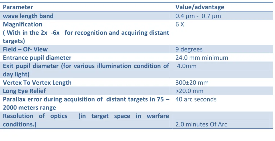
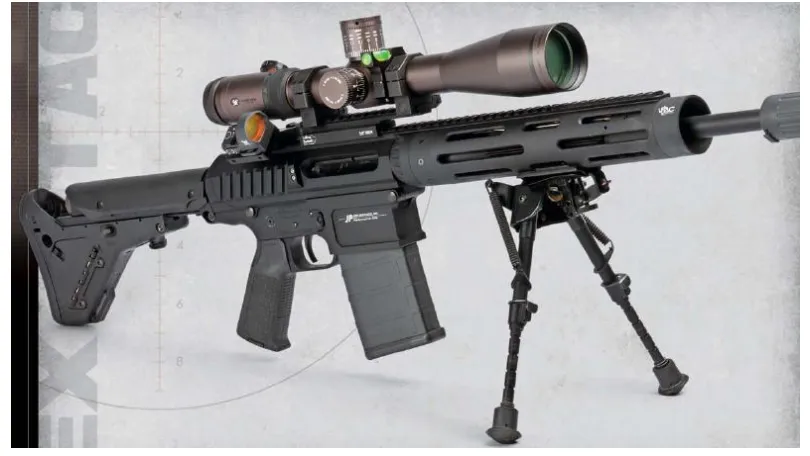
Requirements of the lens system for using as telescopic sight for mounting on soldier heavy machine gun(HMG) is summarized in Table1 and a typical soldier HMG is shown in figure1.
Table 1: Requirements of HMG telescopic sight
Parameter Value/advantage
wave length band 0.4 μm - 0.7 μm
Magnification
( With in the 2x -6x for recognition and acquiring distant targets)
6 X
Field – Of- View 9 degrees
Entrance pupil diameter 24.0 mm minimum
Exit pupil diameter (for various illumination condition of day light)
4.0mm
Vertex To Vertex Length 300±20 mm
Long Eye Relief >20.0 mm
Parallax error during acquisition of distant targets in 75 – 2000 meters range
40 arc seconds
Resolution of optics (in target space in warfare
Available Online at www.ijpret.com 85
Target Range 75 –2000 Meters
Deviation of Centro gravity(cg) of lenses from center of
optical path of optics Minimum
All spherical optics For easy Of fabrication and
testing Repeated radii of curvature values for optical surfaces for
elements in optics
So that the entire optics can be tested with a minimum number of test plates
Sufficient air surfaces between optical elements For easy assembling of elements
in to system
Targets military ambient illuminated
point or area targets of soldier interest in combat at a range of 75 – 2000 meters: personnel, light armored vehicles, low, slow flying aircrafts and small naval boats
Available Online at www.ijpret.com 86
3.0 Configuration of lens system for HMG mounting
The lens systems for day viewing and aiming the distant day illuminated military point or area targets of soldier interest in combat are erected class of telescopic systems with long eye relief. The telescopic sight is constructed with an objective lens, a reticle in the image plane of the objective lens, an erector lens with an aperture stop in between the erector lenses and an eyepiece. The focal lengths of objective lens, erector – eyepiece combination , eyepiece of the day telescopic sight having a vertex to vertex length of 300+ -20mm formounting on soldiers HMG are shown in Table2.
Table 2: Focal length of Objective, Erector, Eye piece of HMG telescopic sight
Lens FOCALLENGTH
Objective lens 93.10 mm
Erector lens 1 35.64 mm
Erector lens 2 31.97 mm
Eye piece 25.0 mm
Eye piece plus erector 15.37 mm
4.0 System design of LENS SYSTEM
The soldier supported with a HMG views and aims the combat point and area military targets which are day illuminated at a range of 75 to2000 meters For targets at medium ranges in the present case, a medium focal length and a medium field of view lens are considered for objective lens of the lens system. The magnification and vertex to vertex length of telescopic sight make the focal lengths of erector and eyepiece smaller than objective. In view of the desired long eye relief ,the aperture stop is considered in between in between erector lenses The aperture stop location at this position provides long eye relief and place the elements in the optical path of sight at a minimum deviation position of CG of telescopic optics[1-3].
4.1 Aberration corrections of lens system
Optical glasses for sight
Available Online at www.ijpret.com 87
4.1.1 Optical design of objective lens
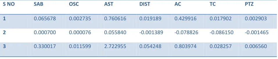
A cemented doublet covers only 5 degrees field – of – view at a speed of f/5.0 for a focal length of 250.0 mm. When the focal length is small, the lens contains deep curvatures and its aberration contributions are large. The corrections of aberrations in short and medium focal length lenses need more than two lenses in its construction depending on the field angle and aperture requirements. In order to restrict the length of the lens system to the requirement, it is inevitable to select the focal length of objective lens in between 90.0 and 100.0 mm. One cemented doublet configuration for objective lens results poor optical performance at f/4.0 and 9 degrees field. The objective lens is configuration is finalized with a front single positive element and a cemented doublet with reticle in the image plane of the objective lens. The Petzval sum of the objective depends on refractive index difference of optical elements and individual powers of elements in the objective lens. It is independent of the shapes of the lenses in the objective lens. A proper balance of Petzval sum is obtained with appropriate powers for individual lenses and index differences of optical glasses used for the lenses in the lens system. It is expected that a minimum Petzval contribution in objective lens may contribute a minimum astigmatism when bending technique is applied to the objective lens. The longitudinal spherical aberration, OSC, astigmatism is corrected in the objective by bending of lenses in objective. The combination of optical glasses and powers of lenses played critical role in the balance of longitudinal chromatic aberration and lateral color. The desired eye relief of lens system does not permit the aperture stop location on or within the lenses of objective lens. As a result, the aperture stop location is not a degree of freedom in the correction of field aberrations of objective lens. The efforts are not made in the design of objective lens to reduce the distortion .It is decided to correct the distortion of objective lens in the design of telescope reticle. [4-8]. The well corrected objective lens for telescopic sight has a positive meniscus element in front and a cemented doublet. It covers a 9 degrees field of view at 93.1 mm focal length. The Seidel aberrations of objective including a reticle in 0.4 μm - - 0.7 μm wave length range is given in Table 3.
Table 3: Seidel aberrations of objective including reticle in 0.4 μm - 0.7 μm wave length range
S NO SAB OSC AST DIST AC TC PTZ
1 0.065678 0.002735 0.760616 0.019189 0.429916 0.017902 0.002903
2 0.000700 0.000076 0.055840 -0.001389 -0.078826 -0.086150 -0.001465
Available Online at www.ijpret.com 88 4 -0.768575 -0.018797 -3.070895 -0.037327 -2.097395 -0.051301 -0.000547
5 0.359579 0.005335 0.528327 0.003741 1.015743 0.015061 -0.000427
6 -0.006432 -0.000103 -0.010943 -0.000087 -0.016104 -0.000257 0.000000
7 0.000041 0.000000 0.000071 0.000000 0.000104 0.0000002 0.000000
SUM +0.018732 +0.000846 +0.985972 +0.037776 +0.057411 +0.001048 +0.007025
4.1.2 Erector lens
The erector lens in a telescopic sight for HMG, shall cover field angles of 9 degrees and large apertures at finite object and image conjugates. The aperture stop is associated with erector lenses .The minimum length between object and image conjugates of any erector lens is four times the focal length. The off- axis rays make significant incident angle on surfaces of erector lenses and as a result contributes to large off- axis aberrations. Also the power of erector lens is positive and large ,the erector lens is configured with two cemented doublets and their shapes considerably reduce coma and astigmatism at finite object and image conjugates. As the objective lens and eyepiece lens work at one infinite conjugate, their field aberrations are small compared with finite conjugate erector lens. The well corrected erector lens for lens system for using it as telescopic sight is constructed with two cemented doublets with negative lenses facing object and image conjugates and positive lenses before and after aperture stop...The positive elements in the erector doublets are biconvex and the negative lenses are meniscus in shape.. The corrected erector lens covers a 9 .0degrees field of view.. The Seidel aberrations of the erector lens are shown in table.
4.1.3 Eyepiece
Available Online at www.ijpret.com 89
4.1.4 Aberration corrections of erector and eye piece
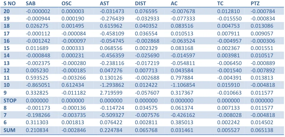
The optical designer corrects the objective lens – erector lens together or eyepiece- erector lens together for aberrations.. We prefer to correct eyepiece- erector together. The erector lens and eye piece are designed separately for minimum on – axis and off- axis aberrations. The Seidel aberrations of erector lens, eyepiece are calculated by ray tracing. These lenses are initially constructed for reasonable values of Seidel aberrations for Petzval sum and two color aberrations. They are improved for coma and astigmatism using bending technique. The actual aberrations are calculated by trigonometric ray trace through these lenses. Bending and optical glassy substitutions are implemented for satisfactory solution for aberrations of these lenses Thus the individually corrected erector and eyepiece are now combined into a single system with aperture stop in between erector doublets and again corrected for Seidel and actual aberrations of the eyepiece and erector lens combination are shown in Table4 The combined focal length of eyepiece and erector combination is 15.37mm.
Table 4: Seidel aberrations of eye piece plus erector from Eye piece end in 0.4 μm - - 0.7 μm wave length band.
S NO SAB OSC AST DIST AC TC PTZ
20 -0.000002 0.000003 -0.031473 0.076595 -0.007678 0.012810 -0.000784
19 -0.000944 0.000190 -0.276439 -0.032933 -0.077333 -0.015550 -0.000834
18 0.026275 0.001495 0.615962 0.040352 0.083516 0.004753 0.013086
17 -0.000112 -0.000084 -0.458109 0.036554 0.010513 0.007911 0.009057
16 -0.001242 -0.000097 -0.054745 -0.002868 -0.063524 -0.004957 -0.000306
15 0.011689 0.000333 0.068556 0.002329 0.083168 0.002367 0.001551
14 -0.000848 0.000231 -0.456359 -0.025690 -0.014597 0.003981 0.010517
13 -0.002375 -0.000280 -0.238116 -0.017219 -0.054811 -0.006450 -0.000889
12 0.005230 -0.000185 0.047276 0.007713 0.043584 -0.001540 -0.007892
11 0.593525 -0.003266 0.130126 -0.002688 0.797884 -0.004391 0.013813
10 -0.865051 0.612434 -1.293862 0.012422 -1.106854 0.015910 -0.004818
9 0.332825 -0.011182 2.719599 -0.057607 0.317367 -0.010663 0.011577
STOP 0.000000 0.000000 0.000000 0.000000 0.000000 0.000000 0.000000
8 -0.001173 -0.000136 -0.114724 0.034575 0.061374 0.007133 0.011577
7 -0.198266 -0.003735 -0.509327 -0.007576 -0.426162 -0.008028 -0.004818
6 0.311303 0.001813 0.076422 0.002811 0.385013 0.002242 0.014502
Available Online at www.ijpret.com 90
4.1.4 Optical design of telescopic sight
The individually corrected objective- reticle combination and eyepiece –erector combination are integrated into a lens system that has the focal properties known as telescope. An axial ray trace through the lens system provides the focal length, back focal length, entrance and exit pupil distances of sight. The exit pupil distance is the eye relief of the lens system The axial and field bundle ray traces give the apertures of lens elements in the lens system
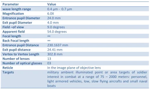
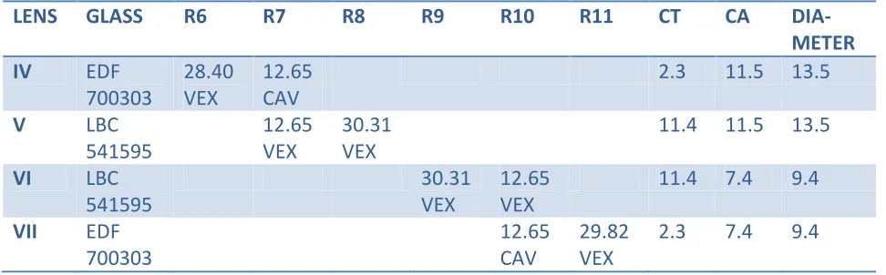
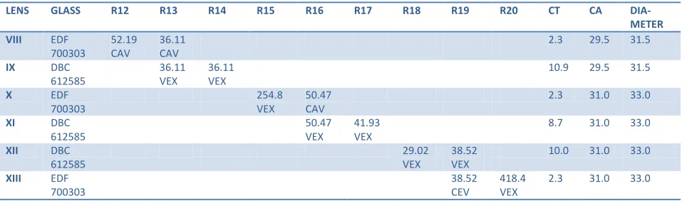
The optical characteristics, optical configuration and optical design data of the complete lens system which is a telescopic sight, objective -retile combination, erector, eyepiece and eyepiece- erector combination are shown in. table 5, figure 2and Table 6.
Table 5(a): optical characteristics of HMG telescopic sight
Parameter Value
wave length range 0.4 μm - 0.7 μm
Magnification 6.0X
Entrance pupil Diameter 24.0 mm
Exit pupil Diameter 4.0 mm
Field –of view 9.0 degrees
Apparent field 54.0 degrees
Focal length ∞
Back Focal length ∞
Entrance pupil Distance 230.1637 mm
Exit pupil distance 24.41 mm
Vertex to Vertex Length 302.8 mm
Number of lenses 13
Number of optical glasses 03
Reticle In the image plane of objective lens
Targets military ambient illuminated point or area targets of soldier
interest in combat at a range of 75 – 2000 meters: personnel, light armored vehicles, low, slow flying aircrafts and small naval boats
Table 5(b): optical characteristics of HMG telescopic sight
Lens system Entrance pupil Distance Exit pupil distance
Objective -230.1416 mm 62.665910mm
Available Online at www.ijpret.com 91
Figure 2: optical configuration of HMG telescopic sight .The drawing is not to the scale.
Table 6(a): optical design data objective lens for HMG telescopic sight
LENS GLASS R1 R2 R3 R4 R5 CT CA DIAMETER
I DBC
612585
130.81 VEX
25.93 CAV
6.1 34.6 36.6
II DBC
612585
57.89 VEX
58.71 VEX
9.5 34.6 36.6
III EDF
700303
58.71 CAV
965.0 CAV
4.3 34.6 36.6
CT= Centre thickness, CA= clear aperture
ALL THE DIMENSIONS ARE IN MM
Table 6(b): optical design data of erector lens for HMG telescopic sight
LENS GLASS R6 R7 R8 R9 R10 R11 CT CA DIA-
METER
IV EDF
700303
28.40 VEX
12.65 CAV
2.3 11.5 13.5
V LBC 541595
12.65 VEX
30.31 VEX
11.4 11.5 13.5
VI LBC 541595
30.31 VEX
12.65 VEX
11.4 7.4 9.4
VII EDF
700303
12.65 CAV
29.82 VEX
2.3 7.4 9.4
Available Online at www.ijpret.com 92
ALL THE DIMENSIONS ARE IN MM
Table 6(c): optical design data of eyepiece for HMG telescopic sight
LENS GLASS R12 R13 R14 R15 R16 R17 R18 R19 R20 CT CA DIA-
METER
VIII EDF
700303
52.19 CAV
36.11 CAV
2.3 29.5 31.5
IX DBC
612585
36.11 VEX
36.11 VEX
10.9 29.5 31.5
X EDF
700303
254.8 VEX
50.47 CAV
2.3 31.0 33.0
XI DBC
612585
50.47 VEX
41.93 VEX
8.7 31.0 33.0
XII DBC
612585
29.02 VEX
38.52 VEX
10.0 31.0 33.0
XIII EDF
700303
38.52 CEV
418.4 VEX
2.3 31.0 33.0
CT= Centre thickness, CA= clear aperture
ALL THE DIMENSIONS ARE IN MM
5.0 CONCLUSIONS
A thirteen element lens system which is a telescopic day sight is designed for mounting on soldier heavy machine gun. This telescopic sight consists of three element objective lens, a two doublet erector lens with an aperture stop in between doublets and a three cemented doublet eyepiece. At 6 X magnification, this day sight covers 9.0 degrees field- of – view with entrance pupil diameter of 24.0mm and an exit pupil diameter of 4.0mm. The vertex to vertex length of the telescopic sight is302.80mm.The sight is designed using only three optical glasses in thirteen elements. The telescopic sight images 75 -2000 meter ambient illuminated military point or area targets in the image plane of objective lens which is reimaged by erector lenses in the object plane of eyepiece. Soldier sees the images of distant targets through an eyepiece from a distance equal to the eye relief of 24.41mm. All the optical surfaces of telescopic sight are spherical and refractive type. The optical design of lens system is unique in its optical characteristics.
REFERENCES
1. Cox. A “A System of Optical Design “, Focal Press, London, p 606, 1964.
Available Online at www.ijpret.com 93
3. Handbook of Optical Systems Vol3.Aberration Theory and Correction of Aberrations. Edited by Herbert Cross, Wiely-VCH Verlag GmbH & Co, Weinheim, Chapter 29, 2007.
4. A.E. Conrady, Applied Optics and Optical Design Part 2, Dover Publication, New York,.pp640-661,1960.
5. Rudolf Kings lake and R. Barry Johnson, Lens Design Fundamentals,pp318-322,Elsevier,Oxford,2010
6. Donald. H. Jacobs, Fundamentals of Optical Engineering, McGraw Hill, New York.pp381-389, 1943.
7. W. J. Smith,” Modern Optical Engineering “, McGraw-Hill. Inc., New York. pp 272-278; pp 247-256; pp 300-302; pp 324-325, 1966.