J
Journal of Aerospace Science and TechnologyA S T
© Iranian Aerospace Society, Summer - Fall 2012
1 Introduction
There has been considerable activity on dynamic crush of thin-walled aluminum tubes during the past decade. the use of these structures in energy absorbing systems. Several researchers studied the crash response of alu-minum tubes with different cross sections geometries and in several points of view; namely, analytical, nu-merical and experimental. Wierzbicki and Abramowicz [1] presented a simple formula to predict the axial crash response of thin-walled columns. Their method is based on the balance of external and internal work. This mod-el was validated experimentally by Abramowizc and Jones [2]. Alexander [3], Pugsley [4], Abramowicz [5] and Abramowicz and Jones [6], Singace and Elsobky [7] and Wierzbicki and Bhat [8] also used the same method to predict the crash behavior of circular tubes.
Parametric Study of the Empty and Foam-Filled End-Capped Conical Tubes under
Quasi Static and Dynamic Impact Loads
A. Ghamarian
1, H.R. Zarei
2!! " # $
Keywords%&''#("
) * "#" !* ' #
)+,,./0+# #"
1 !# #"
&% 213334
Some researchers used crashworthiness optimization maximum energy absorption capacity [9, 10].
According to the previous investigations, thin-walled conical tubes under crushing load achieve different crushing modes based on their length and cross section dimensions. They collapse either in axisymmetric mode (concertina or ring mode) or non axisymmetric mode (diamond mode) or mixed mode [11]. Energy absorp-tion normally takes place by progressive buckling of tubes walls. A distinctive feature of such a deformation mechanism is that the rate of energy dissipation is con-centrated over relatively narrow zones.
Cellular solids are increasingly used in many engi-neering applications like energy absorption, thermal in-sulation and lightweight structures due to their unique property of high porosity. These materials show a dis-tinct plateau of almost constant stress under compres-sive uniaxial load with the nominal strain value up to 80% [15], which indicates high energy absorption ca-pacity. For light weight energy absorber designs, low foam, are preferred to tube with thicker tube walls in terms of achieving the same energy absorption. Metal thin-walled column. This increase is the result of the and the tube walls increase the energy absorption the crushing loads of foam alone and tube alone.
Although several researches have been conducted to circular tubes [16-19], relatively few studies have fo-cused on the energy absorption performance of ! numerical investigations were carried out to establish "#$&' * experimentally found that the energy absorption higher than an empty one. More recently, the crushing -der axial impact loading was investigated [21-23].
The end-capped conical tubes are applied in the nose of sounding rocket as both a cover and an energy ab-sorber. Recently, the energy absorption mechanisms of the end-capped circular and conical tubes as well as circular tubes with shallow spherical caps were inves-tigated [24-26]. The present research is concerned with the response of end-capped conical tubes
under axial compressive load in order to determine the effects of the end cap on the crushing mechanism, crushing load and energy absorption capacity. Several quasi static crash experiments are carried out on is validated using existing experimental results, is used to perform the parametric study. The model is also used to quantify the effect of various parameters on the dynamic response of the tubes. The results demonstrate the advantages of the end-capped conical tubes with a noticeable improvement in the initial peak load and decrease in the deceleration pulse.
2 Experimental test program
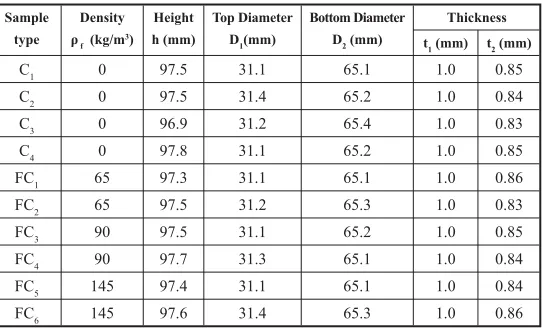
The end-capped conical tubes were fabricated from aluminum plates through spinning process. The circu-lar blanks were cut from commercial aluminum plates with thickness of 1 mm and were stretched over the surface of a rotating die. The end-capped thickness of conical tubes is the same as the blank thickness; how-ever, there is some thickness gradient on conical wall due to stretching the blanks over the die surface. The edge of the formed tubes on the open side was trimmed by moving the cutting tool normal to the rotation axis of the sample at the end of forming process. Some -posed of two components called base and accelerator. end-capped conical tubes are shown in Table 1 with the + //:<< //=:<< conical tube, respectively. The main geometric parame-ters are: the tube wall thickness t, length L, top end di-ameter D1 and bottom end diameter D2. The specimens obtained from the process of spinning were found to have a variation in their thicknesses along the meridian direction. Their thicknesses were found to be maximum t1, at the smaller end and minimum t2, at the larger end; while the variation is almost linear [24,27].
The elastic and plastic behaviors of aluminum materi-als were determined using tensile testing of the coupons cut from plates. Fig. 1a shows the true stress-plastic strain curve for aluminum material. The elastic modu-?< material were determined as 55.7 GPa, 0.3 and 83.3 MPa, respectively. Uniaxial compression tests were performed on the square cubes of polyurethane foams to determine the material parameters at large deforma-tion. The dimension of square cubes was 50 mm and the test was performed in accordance with ASTM D1621– 04 standard. As shown in Fig. 1b, stress-strain curves
Table 1. The geometrical dimensions of empty
Thickness Bottom Diameter
D2 (mm)
Top Diameter
D1(mm)
Height
h (mm) Density
f (kg/m 3)
Sample
type t1 (mm) t2 (mm)
Figure 1. Typical stress-strain curves for (a) aluminum material and (b) polyurethane foams [24].
Quasi-static crash tests were carried out in a 60-ton uni-versal testing machine. The experimental setup is shown in Fig. 2a. The load was applied through a thick steel plate contacting the cap of conical tube. Tests were carried out constant crosshead speed of 10 mm/min. The specimen -chine, as shown in Fig. 2b. The height of circular hole is 3 mm and its diameter matches the outside diameter of tubes. Fig. 3 shows the deformed geometries of the speci-mens. The geometric analysis of specimens revealed that there are low amplitude imperfections in conical tube. Therefore, the conical tubes were buckled in axisymmet-ric deformation mode. The force and displacement of the crosshead were measured during axial compression and the results were used to determine initial peak load, aver-age load and energy absorption capacity of the empty and
Figure 2. (a) Experimental setup and (b) the schematics of
of the polyurethane foams illustrate an initial elastic behavior followed by a plateau region in which there is less variation in stress as the strain increases. Finally,
the stress rapidly increases with further strain in the -tent in porous polyurethane foams.
Figure 3. Photographic views of the deformed geometry for: (a) FC5 (b) FC3 (c) FC1 and (d) C1.
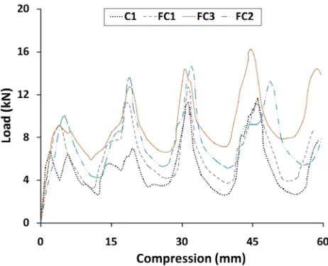
sta-tionary as well as the rolling plastic hinge for the empty Y peaks is corresponding to the number of lobes in de-formed specimens. An important observation is that the conical tubes with higher density tends to lie above the conical tube. This is because the foam constrains the localized buckling of the conical tube wall and more energy is required to bend them. The results obtained conical tubes are shown in Table 2.
polyurethane foam densities
3 Numerical simulation
Y axial quasi-static and dynamic crushing responses of -ulations [28]. The numerical model was able to simulate the buckling and post-buckling problems considering the material and geometric non-linearity. Based on the experimental observations, an axisymmetric condition was considered to model the large deformation of con-ical tubes. Fig. 5 illustrates geometric modeling which `{|`#| `}| was assigned to the moving rigid body to simulate the mass of the impacting device. It was assumed that there was no initial imperfection in the conical tubes and the wall thickness varied linearly between close and open edges.
The geometries of thin-wall tube and foam material were meshed by four-node axisymmetric continuum elements, which were suitable for large plastic "#~& Y -tivity analysis was carried out to obtain accurate results moving bodies were assumed to be rigid compared to the specimen and were meshed using two-node axisym-metric rigid elements.
The axial compression was simulated by applying a constant velocity to the upper rigid surface along y-ax-is, as shown in Fig. 5. Contact boundary condition was considered between the moving rigid surface and the upper surface of the end-capped specimen. To prevent penetration from the wrinkled surfaces of the tube wall during progressive buckling, self-contact conditions were considered on the internal and external surfaces of tube wall. The lower rigid surface was constrained to the ground. The contact boundary conditions were also considered be-tween the bound-ary surface of foam material and inner surfaces of the tube and lower rigid
sur-of friction was set to 0.15 in the contact surfaces. The nodes located at the bot-tom of the tube were surface for the pur-pose of modeling the clamped-end constraint.
Table 2. Results from quasi-static tests conducted on empty and !"
Load ratio #$% Average load
Fave (kN) &
Es (J/gr) Energy absorption
Ea (J) Initial peak load
Fi (kN) Foam
den-sity f (kg/m
T p are true stress and plastic strain, re-spectively. The approximate true stress and plastic models are listed in Table 3.
Table 3. True stress-plastic strain for aluminum material of conical tubes [24]
104.1 102.4 98.2 94.0 90.6 83.3
'T (MPa)
0.154 0.143 0.103 0.074 0.051 0
*P
The mechanical response of aluminum tubes was characterized using elastoplastic model. The plastic be-havior was described by engineering stress and strain measured in uniaxial tensile test, which are denoted here by E and E, respectively. Such measurements were converted to true stress and plastic strain as fol-lows:
(1)
(2)
The mechanical response of polyurethane foam was described by crushable foam material model developed by Deshpande and Fleck [30]. Table 4 lists the material parameters for polyurethane foam based on the crush-able foam model. The elastic modulus of polyurethane foam was determined using the slope of line A–B, ={?< `| plastic (vp) region was assumed to be zero. The initial yield stress in uniaxial compression is the stress value at point B as shown in Fig. 1 and yield stress during the deformation was determined based on the experimental data corresponding to the curve between points B and C. The yield stress ratio (k) was set to a unit value [24]. in uniaxial compression as a function of the absolute value of axial plastic strain. Table 4 tabulates the foam parameters used in this study.
The yield stress in dynamic loading is dependent on plastic strain rate. The empirical power law developed by Cowper-Symonds [31] is used to consider the effect of plastic strain rate on yield stress of both aluminum and foam materials, as follows:
(3)
s d denote the quasi-static and dynamic yield stresses, respectively, and D and m are material constants [32-33].
6
The calculated response parameters from the FE mod-els are:
1. Crushing length (X), which is the length of de-formed tubes
2. The initial peak crush load (Fi )
3. The mean crush load (Fave | load calculated for a reduction in tube length
4. ! `a), which is the energy absorbed by the tube divided by the total mass of the tube
5. `| = it was validated against the experimental data. The = compared with the experimental observation.
!7 $%$% 8+9;<
and experimental results.
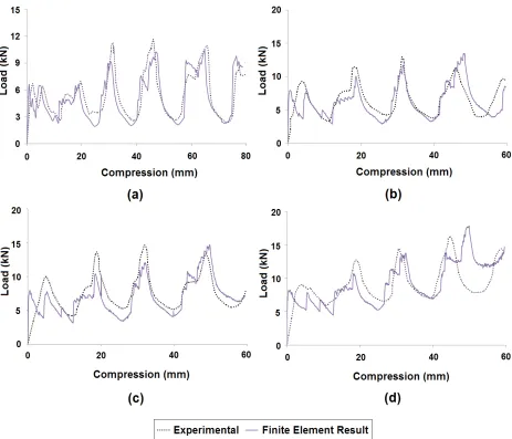
Experimental and numerical crash load-deformation curves are plotted in Fig.7. It is observed that the X correspond to the initial collapse when the conical tube behaves elastically. The separation of the end-capped surface from upper rigid surface leads to forming the the next fold is generated, while it is moved toward the inside of tube. Such folds act as imperfection causing the next folds to be generated adjacent to the previous O around a mean value of the axial force.
Table4. Tabulated crushable foam mechanical properties used in simulation [24]
Density (kg/m3) Elasticity Plasticity
E(MPa) k vp
65 5.5 0 1 0
90 10.9 0 1 0
5 Dynamic loading
Y capped conical tubes subjected to axial impact loading. The effect of strain rate on the yield stress is described by Eq. (3), the parameters of which are listed in Table 5 for both aluminum and foam materials. The numerical model was used to calculate the energy absorption ca-pacities of the conical end-capped tubes under different impact velocities. It was also of the interest to quanti-fy the effect of the various parameters of the tubes on the dynamic responses and then compare them with the Factor (DAF). This factor is important in a simple de-sign procedure as it can be used to estimate the dynamic effect from the static analyses without conducting actual dynamic analyses or tests. In the present study, the DAF
represented the ratio of energy absorbed under dynamic loading to the energy absorbed under quasi static load-ing for the various impact velocities and foam densities with a constant impact mass. In this section, the DAF of the empty conical tube was compared with conical tube {K3 for varying wall
thickness, semi-apical angle and impact velocity.
Figure 7. Comparison of experimental and numerical static load-displacement curves for (a) C1, (b) FC1, (c) FC3, and (d) FC5
Table 5. Parameters describing the strain rate effect on yield stress of aluminum and polyurethane foam materials [24,34]
Material D (s-1) m
Aluminum 1288000 4
5.1 Effect of impact velocity on the DAF
= = = _X = = = = === KK K $
?@ $%$% G$9K8MK8""M K8"MKO"9%
UV 9W,$%$% $K8""M K8"MKO"9%
5.2 Effect of wall thickness on the DAF
{ {$ ={$O = of each tube is reduced as the semi-apical angle increas-{$O {$ all in all, due to the variation in the semi-apical angle, the DAF can be as high as 11% to 15% for the empty 10 m/s.
5.4 Effect of foam density on the DAF
Finally, the effect of foam density on the DAF at an im-pact velocity of 10 m/s is illustrated in Fig. 11. In the foam density on the DAF. No distinct trend is ob-served when varying the foam density with increasing + = -O = a constant wall thickness and semi-apical angle. Here, it can be seen that when the foam density increases, the ={{= ~$ } }
X -ferent impact velocities are presented in table 6. Here, the energy absorptions of the tubes at 60 mm deforma-tions are considered. From this table it is clear that the X-nesses of 1 and 1.5 mm under dynamic loading are higher than quasi-static loading.
@ !& $K8""M K8"%
5.3 Effect of semi-apical angle on the DAF
It was also interesting to investigate the effect of semi-apical angle on the DAF of absorbed energy of the
Thickness K8
Type of loading Quasi-static Dynamic (10 m/s)
Difference (%)
Empty 11.83 12.58 6.34
Filled (with density 145 kg/m3) 12.57 14.54 14.95
Tickness K8+
Type of loading Quasi-static Dynamic (10 m/s)
Difference (%)
Empty 13.37 14.70 9.94
Filled (with density 145 kg/m3) 14.23 15.58 9.48
887 G$9K8M
K8""M K8"MKO"9%
6 Conclusions
A numerical simulation procedure was developed to Y end-capped conical tubes considering the nonlinear response due to large deformation, contact boundary conditions, work hardening and strain rate effects on material behavior. Based on the experimental results obtained for end-capped tubes, it was shown that the numerical method predicts the buckling and post-buck-ling responses with a reasonable accuracy. With the use of numerical simulations, the effects of tube parameters as well as foam density and impact velocity on the dy-namic responses of the tubes were studied. The exper-imental and numerical studies conclude the following results:
The presence of polyurethane foam in conical tubes has little effect on increasing the load and absorption.
The DAF of empty end-capped conical tubes is in-creased when the impact velocity increases; while
For a constant impact velocity, the DAF of the
The thickness of the tube has a considerable effect on the DAF. The DAF of the empty tubes, unlike thickness towards the start and end of the crush process.
different thicknesses under dynamic loading are higher than that of the quasi-static one.
= X
empty one.
The DAF of each tube is reduced as the semi-apical angle increases from 5° to 10°.
= =
of empty ones for a constant wall thickness and semi-apical angle.
=
~$} a foam density of 65 Kg/m3.
References
1. Wierzbicki T, Abramowizc W. On the crashing mechanics of thin-walled structures. J Appl Mech 1983; 50:727-39.
2. Abramowizc W, JonesN. Dynamic axial crashing of square tubes. Int. J. Impact Eng 1984; 2:263-81. 3. Alexander JM. An approximate analysis of the col-lapse of thin cylindrical shells under axial laoding. Q J. Mech.Appl Math 1960; 13:10-15.
4. Pugsley AG. On the crumpling of thin tubular structures. Q J. Mech.Appl Math 1979; 32:1-7. 5. Abramowicz W. The effective crushing distance in
axially compressed thin-walled metal columns. Int. J. Impact Eng 1983; 1:309-17.
6. Abramowicz W, Jones N. Dynamic axial crushing of circular tubes. Int. J. Impact Eng 1984;2:179-281.
7. Singac AA, Elsobky H. Further experimental in-vestigation on the eccentricity factor in the pro-gressive crushing of tubes. Int. J. Solids Structure 1996; 32(3):589-602.
9. + -thiness optimization of circular aluminum tubes. Thin-Walled Structure J 2006; 44:301-8.
10. Y X + Y -ing energy absorption of tubes, Structure Optimi-zation, 1998 16 37-49.
11. ! ' * Shanmugapriyan N. Optimization of thin conical frusta for impact energy absorption. Thin-Walled Structure J 2008; 46: 653-66.
12. ? ' ' study of deformation modes of domes and large-an-gled frusta at different rates of compression. Int. J. Impact Eng 2005; 32:400-15.
13. ' !* study on buckling of thin conical frusta under axial loads. Thin-Walled Structure J 2006; 44:986-96. 14. ' *X
-ical studies of impact axial compression of thin-walled conical shells. Int. J. Impact Eng 2007; 34: 708-20.
15. Gibson L. J, Ashby M. F. Structure and Proper-ties, 2nd, Cambridge University Press, Cambridge, 1997; 1-510.
16. ! tapered sheet metal tubes. Int J Mech Sci; 1986; 28(10):643-56.
17. + : & Design 2008; 29:193-204.
18. + Structure J 2008; 46, pp. 214-21.
19. +\ ¡ ! Y Int. J. Impact Eng 2008; 35: 521-28.
20. ' * Composite Materials 1999; 33(6):567-91.
21. Mirfendereski L, Salimi M, Ziaei-Rad S. Para-metric study and numerical analysis of empty and -namic loadings. Int J Mech Sci 2008; 50(6): 1042-57.
22. Ahmad Z, Thambiratnam DP. Crushing response loading. Materials & Design 2009; 30(7):2393-403. 23. Ahmad Z, Thambiratnam DP. Dynamic computer
conical tubes under axial impact loading. Comput-ers & Structures 2009; 87(3-4):186-97.
24. A. Ghamarian, M.T Abadi, Axial crushing analysis of end-capped circular tubes. Thin-Walled Struct. 49(2011) 743-752.
25. A. Ghamarian, H.R Zarei, M.T Abadi, Experimen-tal and numerical crashworthiness investigation of Thin-Walled Struct. 49 (2011) 1312-1319.
26. A. Ghamarian, H.R Zarei, Crashworthiness in-vestigation of conical and cylindrical end-capped tubes under quasi static crash loading. Int. J. Crash-worthiness 17 (2012) 19-28.
27. ' ? ' ' ! ? -tic collapse of metallic conical frusta of large semi-apical angles. Int J of Crashworthiness 1997; 2:349-66.
28. ¢ ? X¡+ & Sorensen;1999
29. Aljawi A.A.N. and Alghamdi A.A.A, Abu-Man-sour T.M.N, Akyurt M. Inward inversion of end-capped frusta as impact energy absorbers. Thin-Walled Structure J 2005; 43: 647-664.
30. Deshpandeh VS, Fleck NA. Multi-axial yield be-havior of polymer foams. Acta materialia 2001; 49:1859-66.
31. Symonds P.S., Viscoplastic behavior in response of ¡+ (Ed.), Behavior of materials under dynamic load-ing. New York: SME; 1965, pp. 106-24.
32. Y O in axisymmetrically deformed cylindrical shells under axial impact, Int. J. Impact Eng. 24 (2000) 1083-115.
![Figure 1. Typical stress-strain curves for (a) aluminum material and (b) polyurethane foams [24].](https://thumb-us.123doks.com/thumbv2/123dok_us/8946479.1855847/3.595.312.531.390.608/figure-typical-stress-strain-curves-aluminum-material-polyurethane.webp)
![Table 3. True stress-plastic strain for aluminum material of conical tubes [24]](https://thumb-us.123doks.com/thumbv2/123dok_us/8946479.1855847/5.595.65.532.104.495/table-true-stress-plastic-strain-aluminum-material-conical.webp)