NUMERICAL STUDY OF HIGH DENSITY POLYETHYLENE – PCM
CAPSULES FOR PASSIVE COOLING APPLICATION IN
INTERMODAL STEEL BUILDING SPACE ENVELOPE
A. N. Udosen*
D
EPARTMENT OFM
ECHANICALE
NGINEERING,
U
NIVERSITY OFN
IGERIA,
N
SUKKA,
E
NUGUS
TATE.
NIGERIA
E-mail address: [email protected]
ABSTRACT
The Intermodal Steel Building envelope commonly called shipping container or ‘the conex box’ is gradually becoming a common option for occupants who use them for commercial or residential purposes due to its relatively cheap cost compared to conventional brick or concrete structure houses. The conex box is mainly made of high density steel with high thermal conductivity, which results to increased and uncomfortable indoor space temperatures for its occupants. In Nigeria, the indoor space temperature of the conex box is often high because of the relatively high daytime ambient temperature, usually 30oC and above especially in the Northern part of Nigeria. This has
led to the dependence on mechanical air conditioning to achieve human thermal comfort within the conex box. The net effect of this will be the over dependence on the already stretched and insufficient power from grid connected electricity. This work investigates numerically the potentials of high density polyethylene PCM (phase change material) capsules for passive cooling application in a typical intermodal steel building space enclosure. Numerical results obtained from the Matlab programme software showed that exposing the HDPE-PCM panel system to high ambient temperature is capable of causing significant ambient temperature depressions of 7.1 – 10.2oC for
four simulation days. It is recommended that further simulation and experimental study is carried out with reverse suction DC fan(s) placed at strategic locations on the steel container walls for air quality recirculation and removal. The results obtained from this study shows that the modelled HDPE-PCM panel system for passive cooling application in shipping container homes, is possible and when properly implemented has the capability of reducing over dependency on mechanical air conditioning systems even for conventional concrete and brick building structures.
Keywords: Latent heat; Paraffin wax; Polyethylene, Passive Cooling; Conex Box;
1. INTRODUCTION
Passive cooling uses free, renewable sources of energy such as the sun and wind to provide cooling, ventilation and lighting needs for a household [1]. Passive cooling has the potentials to be combined with or completely eliminate the need to use mechanical cooling strategies to provide thermal comfort for occupants [1-2]. It can also reduce levels of energy use and environmental impacts such as greenhouse gas emissions. Passive space cooling with Phase Change Materials (PCMs) has grown recently in the last decade offering less cost for its applications with reduced environmental hazard concerns. Phase Change Material typically referred to as
latent heat storage material is sensitive to source or surrounding temperature fluctuations. In its operation, the chemical bonds within the PCM breaks up and the material changes its phase from solid to liquid or liquid to solid. This phase change is either referred to as charging or discharging process. When the PCM material begins to melt its temperature remains approximately constant until the melting process is completed. The heat stored during the phase change process (melting process) of the material is called Latent Heat. The incorporation of PCMs for thermal applications such as space heating/cooling, solar cooking, large concentrating solar power plants etc, have received much attention and investigations in the
Nigerian Journal of Technology (NIJOTECH)
Vol. 38, No. 2, April 2019, pp.
387 – 400
Copyright© Faculty of Engineering, University of Nigeria, Nsukka,industrialized countries in the past four to five decades because of the ever increasing energy cost and environmental concerns. According to [3], the most promising of the storage media available are the normal paraffin because of their very good latent heat storage capacity, high heat of fusion and high volumetric energy densities to accommodate small temperature swings. The integration of PCMs in building have been investigated, especially with the advent of PCM implemented in gypsum board, plaster, concrete and other wall covering materials. Advanced countries, presently mainly integrate PCM in passive solar building systems for space heating and in active systems for water heating in buildings. An example is the storage of summer heat for winter space heating, and storage of solar energy for hot water use at night. In the United States, light weight building construction practice is common place allowing for light weight PCM system to be installed. Again in [2], the authors add that systems like wallboard and panels containing PCM that melts at room temperature is suitable for lightweight structures where the PCM also serves as a panel structural component to provide additional wall thermal mass. The authors in [4], studied cases where PCM was directly integrated into building materials by mixing granulated paraffin wax with concrete or cement. They observed that this method interfered with building structures because the concrete strength was compromised while the PCM properties changed and caused a major leakage problem that corrodes the steel bars in building structures. A prominent method of integration of PCMs in construction materials such as paints, cement, lime, mortar, etc has been found to be the microencapsulation technology. This work is an attempt to investigate the possibilities of using high density polyethylene PCM (paraffin wax) capsules for space cooling of commonly used Intermodal steel building envelopes.
2. REVIEW OF RELEVANT WORKS ON PASSIVE HEATING/COOLING APPLICATION OF PCMS IN HEATING VENTILATION AND AIR-CONDITIONING (HVAC) LOW ENERGY BUILDINGS
Passive methods integrate PCMs with appropriate melting temperatures mostly adopted into building materials such as walls and ceiling, or inside of ducting at suitable locations (e.g window openings) basically to store cold from night air for daytime cooling or vice versa. Akar and Medved [5] noted that passively integrated Thermal Energy Storage (TES) can be used with solar energy or other renewable energy sources to facilitate effective energy managements. Hybrid system which integrates both active and passive cooling/heating strategies can also be utilized together to decrease HVAC energy
requirements and operating costs and improve comfort in indoor living and work spaces [3]. According to [3], an important performance factor in the design of passive cooling systems using latent TES is the appropriate PCM melting point. A numerical assessment of the performance of a vertical cylinder filled with spherical encapsulated RT20 paraffin PCM was studied by [4]. The authors numerically modeled and developed a latent heat thermal energy storage (LHTES) device to identify the parameters that have influence on the LHTES’s thermal response in order to determine the optimum phase-change temperature, and to form the LHTES’s temperature-response function which defines the LHTES’s outlets-air temperature for a periodic variation of the inlet ambient air temperature. The temperature-response was then integrated into the TRNSYS building thermal response model. Numerical simulations showed that a PCM with melting temperature between 20 and 220C is the most suitable for free cooling in the case of a
thermal barrier effect, providing a stable room temperature variation through a heat flux reduction. In the work done by [9], the authors numerically and experimentally examined the use of latent TES for free cooling for a range of climate conditions. They suggested an optimal latent TES based on the ratio of PCM mass and ventilation – air volume flow rate. The authors concluded that the PCM with the widest phase change temperature range of 12K was found to be the most efficient for the climate conditions analyzed. The optimal PCM mass for the free cooling of a room was found to be 1-1.5kg per m3/h of fresh ventilation air.
3. HDPE-PCM PANEL SIMULATED MODEL DESCRIPTION
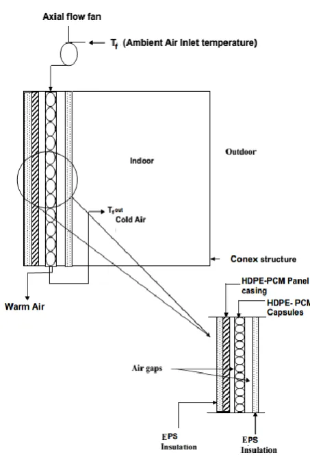
The HDPE-PCM panel medium is the storage model used for this study and was generated using the solid works simulation tool. The HDPE-PCM panel medium of HDPE shelled balls or capsules arranged on a specially constructed wire gauze, filled with technical grade paraffin wax as the PCM. The HDPE-PCM panel medium is externally insulated with expanded polystyrene board on the sides to avoid heat losses. The capsule shells have HDPE coating thickness of 0.8mm with capsule outer diameter of 60mm. The method of paraffin packaging is by microencapsulation. The thermophysical properties of the PCM and HDPE are presented in Tables 1 and 2 respectively. The HDPE panel setup consist of HDPE capsules arranged in a panel medium where its thermodynamic and structural effects on the capsule are negligible in this study. The paraffin used is ecologically/environmentally friendly and 100% recyclable. The paraffin is mainly used in low energy buildings for cooling due to its melting temperatures between 23-25⁰C and with latent heat of fusion between 214.4 kJ/kg. The surrounding heat transfer fluid (HTF) for the system is ambient air, propelled using a high pressure axial flow fan placed at the air-inlet channel of the panel medium with each fan speed of 500rpm. The realistic behaviour of the PCM modelled in this study during the melting and solidification processes was observed and reported by [10] using the differential scanning calorimetry (DSC) measurements with Mettler TA 4000 thermo-analysis equipment.
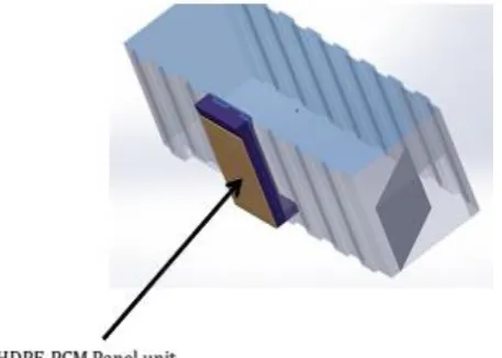
Figure 1: Intermodal steel building envelope Model used for the study
Figure 2: HDPE-PCM Panel Simulated Model Schematic
Table 1: Thermophysical properties of a paraffin wax phase change material used for the study.
Properties Value
Specific heat capacity (solid) 2 KJkg-1K-1
Specific heat capacity (liquid) 3.2 KJkg-1K-1
Thermal conductivity (solid) 2 Wm-1K-1
Thermal conductivity (liquid) 0.55 Wm-1K-1
Enthalpy of fusion 214.4 kJkg-1
Density (solid) 1500kgm-3
Density (liquid) 1530kgm-3
Viscosity 1.07×10⁻⁶ kgm-1s-1
Source [12]
Table 2: Thermophysical properties of HDPE capsule material used for the study.
Properties Value
Thermal diffusivity 1.96x10⁻⁷ m2s-1
Thermal conductivity 0.35 Wm-1K-1
Density 940 kgm-3
Specific heat capacity 1.9 KJkg-1K-1
Melting point 108°C
Emissivity 0.8-0.9
Table 3: Thermophysical properties of air at 29.7°C, 1 atm used for the study.
Properties Value
Thermal conductivity 0.02588 Wm-1K-1
Specific heat capacity 1007 KJkg-1K-1
Dynamic viscosity 1.872 x 10⁻⁵ kgm-1s-1
Prandtl number 0.7282
4. NUMERICAL MODELLING APPROACH
A combination of the explicit-first order finite difference (FDM) and the effective heat capacity (EHC) methods were adopted as numerical methods used in discretizing and solving the PCM model equations. While the HDPE equations were discretised using FDM method. Assumptions used to simplify the analysis are as follows: 1. Ambient air, Paraffin wax and HDPE shell
temperature varies along the radial direction of each PCM capsule; Tf = Tf(r), Tw = Tw (r) and Tp = Tp(r).
2. One dimensional transient state is considered for the paraffin wax and HDPE shell hence; ∂T
∂θ ⁄ =
0, ∂T ∂∅⁄ = 0, ∂T ∂t⁄ ≠ 0
3. No internal heat generation in the PCM capsules; ∅
= 0.
4. The PCM regime inside the HDPE capsule is assumed to be solid dominated, therefore the convective heat transfer during phase change in the solid-liquid or liquid-solid interface is neglected.
5. The HDPE-PCM capsules are exposed to air flowing through high pressure axial flow fans at varying ambient temperatures with constant speed of 500rpm.
6. The densities of the HDPE shells and paraffin wax are constant.
7. The momentum equations for the air flow into the HDPE-PCM panel medium are negligible, hence air flow is a function of temperature only.
8. Radiant heat transfer between the capsules is negligible.
9. Thermophysical properties of HDPE shells and paraffin wax do not vary with time.
10. Thermophysical properties of the inlet ambient air into the HDPE-PCM panel medium is constant at an average temperature of the highest daily temperature values.
11. The sides of HDPE-PCM panel medium is externally well insulated with Expended Polystyrene (EPS) board, therefore heat loss from the panel medium system is negligible.
12. The PCM discharge/solidification numerical algorithms are not coupled with the air flow temperature function, hence the heat discharge
effects from PCM is shielded from the air flow throughout HDPE-PCM panel unit.
Figure.3: Schematic of the air flow in the axial direction of the HDPE-PCM System, Source: [16]
4.1 Governing Equations
To solve the Airflow and HDPE-PCM simulation problem, the above stated assumptions are considered hence, a one-dimensional heat model is developed for the PCM used in this study for selected nodes 0 – 43. In the same way, the mathematical models for the Air-HDPE material interaction is derived as follows:
4.1.2 Energy balance analysis about HDPE-PCM capsule outer node 0
Figure 4: Energy balance analysis about node 0(first row/inlet capsules) of the HDPE-PCM panel,
Source: [16]
The governing equation is thus written for nodes 0 and 44 in equation (1).
ℓpCppAs
𝜕r 2
𝜕Tp
𝜕t = kp
r2As
𝜕 𝜕r
r2𝜕(T
p1− Tp0)
𝜕r
+ hfAs(Tf0− Tp0) (1)
Equation (1) can be written as
ℓpCppAs
𝜕r 2
𝜕Tp
𝜕t = kp
r As
𝜕2(r(𝑇
𝑝1− Tp0))
𝜕r2
+ hfAs(Tf0− Tp0) (2)
Initial Conditions:
Tf (r,0)= Tf in (3)
Tp (r0,0)= Tp intial (4)
Boundary Conditions:
Tf (r,t)= −
hf
kp[Tp(r,t)− Tf(r,t)] (5) Tp (r0,t)= −kp[Tp(r2,t)− Tp(r1,t)] (6)
To simplify the governing equation (1) for a suitable numerical approach implementation, the following applicable dimensionless parameters ae defined.
r∗= r rh , τ
∗= t t0, θ =
T−Tp
Tf−Tp
Let Tp= Tp1− Tp0 in equation (1) for simplicity thus
substituting the dimensionless parameters into equation (1) gives
ℓpCppAst0
(r∗r h)2
2 𝜕Tp
𝜕τ∗
= kpAst0𝜕(T − Tp) + Tf 𝜕r∗𝜕θ
+ Ashf kp
(Tf0− Tp0) (7)
Dividing through by Ast0r∗rh gives
ℓpCpp
r∗r h
2 𝜕Tp
𝜕τ∗=
kp
r∗r h
𝜕(T − Tp) + Tf
𝜕r∗𝜕θ
+ hf t0r∗rhkp2
(Tf0− Tp0) (8)
Dividing equation (8) by kp and multiplying the solution
with ∝p= kp
ℓpCpp gives:
r∗r h
2 𝜕Tp
𝜕τ∗=
∝p
r∗r h
𝜕(T − Tp) + Tf
𝜕r∗𝜕θ
+ ∝p t0r∗r
hkp
hf(Tf0− Tp0) (9)
By the order of magnitude analysis of equation (9) both terms in the RHS can be compared and viewed to have about the same magnitude hence, no justification to neglect one term in preference to the other, thus both terms in equation (9) are retained. Substituting
Tp= Tp1− Tp0 andθ = T−Tp
Tf−Tp back to equation (9) yields
r∗r h
2 𝜕Tp 𝜕τ∗=
∝p r∗r h
𝜕(Tp1− Tp0) 𝜕r∗
+ ∝p t0r∗r
hkp
hf(Tf0− Tp0) (10)
Multiplying through by r∗r h
∝p gives
(r∗r h)2
2 ∝p 𝜕Tp
𝜕τ∗=
𝜕(Tp1− Tp0)
𝜕r∗ +
hf
t0kp (Tf0− Tp0) (11)
Equation (11) is multiplied by ∝p= kp
ℓpCpp to yield
(r∗r h)2
2 𝜕Tp 𝜕τ∗∙=
kp ℓpCpp
𝜕(Tp1− Tp0) 𝜕r∗
+ hf t0ℓpCpp
(Tf0− Tp0) (12)
Dividing equation (12) by (r∗r h)2
2 where r ∗= r
rh, equation (12) becomes
𝜕Tp
𝜕τ∗∙=
2kp
ℓpCpp𝑟2
𝜕(Tp1− Tp0)𝑟ℎ
𝜕r
+ 2hf
t0ℓpCpp𝑟2(Tf0− Tp0) (13)
Multiplying through by r2 2 gives
r2𝜕T p
2𝜕τ∗ =
kp ℓpCpp
𝜕(Tp1− Tp0)𝑟ℎ 𝜕r
+ t ∗ hf τ∗ℓ
pCpp
(Tf0− Tp0) (14)
Discretizing equation (14) using the simple explicit and first order finite difference formulation, gives
Tpo,i n+1− T po,i n
2∆t Δr
2 = kp
ℓpCpp
Tp1,i+1 n − T po,i n
∆r
+ hf ℓpCpp
Tfon− T po,in
∆t (15)
Multiplying equation (15) by 2∆t
Δr2, having that αp=
kp
ℓpCpp gives
Tpo,i n+1 = αp2hf
kpΔr2
(Tfo,i n − T po,i n ) +
2∆t αp
∆r3 (Tp1,i+1 n − Tpo,i n)
+ Tpo,i n (16)
Recognizing that Fo= αp∆t
∆r2 , hence
Tpo,i n+1 = 2F o
hf ∆t (Tfo,i
n − T po,i n ) +
2Fo
∆r (Tp1,i+1
n − T po,i n )
Equation (18-25) were used to determine the convective heat transfer coefficient of the ambient air flowing throughout the HDPE-PCM panel unit at steady state. The temperature performances of both the flowing air and the HDPE capsule material are solely dependent on the operation of the PCM. Hence, to determine the value for the computational time ∆t in equation (17), a stability
criterion analysis of the Paraffin wax is performed in equation (88).
hf=
Nu × kf
μf
(18)
Nu = 7.541 + (0.02(1 − ε)
0.6× Re0.6× P r
h )
1 3 ⁄
(19)
Where the Reynolds number, Re =ℓf∗C∗h
μf
, C =Qv
AD & ∆r =
h
Ny , where h = 2.65m being the HDPE-PCM panel height considered as the length of the axial air flow region, N = 44 being the number of capsules arranged in the axial y direction and ∆r = 0.06m being the outer diameter of
each capsule. AD= 1.392𝑚2 being the duct area for one
axial flow fan, Qv is the volume flow rate of the fan at
500rpm.
Equation (19), was developed by [13] as a correlation to determine the Nusselt number for a forced convection PCM/Air exchange system for building application. In equation (19), the porosity, 𝜀 = 0.9 of the HDPE-PCM
panel is determined using equation (20) developed by [14] for packed capsule systems.
𝜀 = Vp− Vo
Vp (20) Vp is the volume of paraffin wax storage in the HDPE
capsules, Vo is the volume of the void fraction in the
HDPE-PCM panel medium. In determining the volume of the void fraction, equation (21) is used.
Vo=
Ap
As
(21)
Ap= 15.9𝑚2 being the area of the HDPE-PCM panel
medium and As= 0.0113𝑚2 being the surface area of
each capsule. The determination of Vp in equation (20)
requires the solutions of equation (22-25).
Vp=
4
3𝜋(𝑅 − tp)
3
(22)
Where 𝑅 = 0.03𝑚 being the external radius of each HDPE
capsule and tp= 0.8mm being the thickness of the HDPE
shell coating of the capsules.
ms= Vp× (ℓw+ ℓp) (23)
Numerical values for ℓw & ℓp are obtained in tables 1 and
2
mp= ms× Nc (24)
The mass of the entire HDPE-PCM panel is mp= 629.2kg,
while the mass of a single capsule ms= 0.143kg Nc= Ny× Nx (25)
Ny= 44 being the number of HDPE capsules packed in
the y-axis (axial flow direction), while Nx= 100 being the
number of HDPE capsules packed in the x –axis. A total of Nc= 4,400 HDPE capsules occupy the panel medium
of study. By substituting parameters in tables 1, 2 & 3 and the solutions of equations (18-25) into equation (17), the numerical values for Fo, hf & ∆r is obtained.
Therefore, equation (19) becomes
Tpo,i n+1 = 0.073(Tfo,i n − Tpo,i n) + 16.30(Tp1,i+1 n − Tpo,i n )
+ Tpo,i n (26)
Equation (26) is the numerical algorithm used to predict the temperature fluctuations of nodes 0 and 44 only and can be written for new time steps forming a system of N-algebraic linear equations as follows;
Tpo,i n+1 = 16.30(T
P1,i+1 n + 4.47 × 10⁻³ Tfo,i n) − 15.37TPo,i n
TPo,I n+2= 16.30(T
P1,i+1 n+1 + 4.47 × 10⁻³ Tfo,i n+1) − 15.37TPo,i n+1
TPo,i n+∞= 16.30(TP1,i+1 n+(∞−1)
+ 4.47 × 10⁻³T fo,i
n+(∞−1)
) −
15.37TPo,i n+(∞−1)
4.1.3 Determination of HDPE shell surface nodal temperatures at first iteration time step, 𝑻𝑷𝒐,𝒊 𝒏
The HDPE capsule surface node temperature accounts for the temperature distribution across discrete nodes on each capsule surface without any physical interaction with the PCM as a result of energy transferred by ambient air to the HDPE material. Therefore, the governing equation for surface nodes (1-44) at first time step can be derived from the surface energy balance given below applicable at steady-state conditions neglecting radiant heat transfer.
Figure 5: Energy balance analysis about HDPE shell surface temperature for nodes 0 – 44 at steady state, Source: [16]
qcond= qconv+ qrad (27)
qcond= kp AptT∞
n− T s
h (28) qconv= hf Apt ∆ Tlm (29)
Where Є is the emissivity of HDPE shell between (0.8 – 0.9), and б is the Stefan Boltzmann Constant (5.67*10-8
W/m2K4). The unknown is T
s (surface Node temperature)
and cannot be solved explicitly because of the fourth power dependence of the radiation term. Therefore the radiation heat flux qradcan be written in terms of the
radiation heat transfer coefficient as in equation (30). By Substituting equations (28 – 30) into equation (29) gives:
kpApt
T∞ n − Ts
h = hf Apt ∆TIm+ hr (Tr− T∞) (31)
Based on the assumptions, the radiative heat transfer coefficient hr within the capsules is negligible. Therefore,
the surface nodal energy balance equation (31) is reduced to (32):
kpApt
T∞ n − Ts
h = hf Apt ∆TIm (32)
Where ∆Tim is the log-mean temperature difference, Apt
is the surface area of all the capsules in the panel medium given by Apt= Ap∗ 𝜀 and T∞ n is the ambient
temperature at first iteration time step -12am for the hottest of simulation day 1-4.
∆Tlm=
(Tpinitial− T∞mid) − (Tpinitial− To)
In ( TpinitialT − T∞mid
pinitial− To )
(33)
The log-mean temperature difference ∆Tlm developed by
[15] where T∞mid is the mid-daytime ambient
temperature, Tpinitialis the initial HDPE-PCM panel
temperature, To is the estimated outlet temperature. In
determining the value of estimated outlet temperature To, the expression below by [15] is adopted to so that the
log-mean temperature difference ∆Tim= 0.011℃. Tpinitial− To
Tpinitial− T∞mid
= exp (− hf Apt ℓf× C × Ap × Cpf
) (34)
Rearranging equation (32) in terms of qconvyields
kpApt T∞
n− T s
h = qconv (35)
Taking Ts= Tpo,in and T
∞n = Tfo,in = 29.0℃ (Average
ambient temperature for day 1- 4), hence equation (35) becomes
Tpo,in = Tfo,in −
r × qconv
Apt× kp (36)
Tpn(r0) =
x2
2kp
(1 − x
2
h2) + Tpo,in ; 𝑟0= ∆h ± 0.06m (37)
Where 𝑟0 is the nodal increment along HDPE-PCM panel
height for nodes 0-44.Equation (37) is written for first iteration time(12am) for day 1-4 as presented in equations (38 – 41). All ambient temperature data were obtained using the Arduino Uno and type K thermocouple sensors.
Day 1:
Tpn(r) = 0.021 (1 − x2
h2) + 20.99
o C (38)
Day 2:
Tpn(r) = 0.021 (1 − x2
h2) + 22.99
o C (39)
Day 3:
Tpn(r) = 0.021 (1 − x2
h2) + 24.29
o C (40)
Day 4:
Tpn(r) = 0.021 (1 − x2
h2) + 23.79
o C (41)
Equations (38 - 41) can be solved using MATLAB to derive numerical temperature results for panel nodes 0 - 44 for first iteration time step.
The Energy balance analysis about PCM is the sum of heat quantity transferred by conduction from node 1 to node 2 across capsule space Δr and heat transfer by conduction from node 3 to node 2 across capsule space Δr equals rise in temperature at node 2 within the control volume As∆r due to energy accumulation at node 2 [11].
Figure 6: Energy balance analysis about internal nodes 1-43 of the HDPE-PCM capsules,
Source: [16]
The governing equation for HDPE-PCM internal nodes 1-43 can be written following the energy balance technique and yields
ℓpCppAs
𝜕Tp
𝜕t = ∅ + kp
r2 As
𝜕 𝜕r
r2𝜕(T
p1− Tp2)
𝜕r
+ kp r2As
𝜕 𝜕r
r2𝜕(T
p2− Tp3)
𝜕r (42)
Applying assumption three reduces equation (42) to give
ℓpCppAs𝜕Tp 𝜕t =
kp
r As
𝜕2(r(𝑇
𝑝1− Tp2))
𝜕r2
+ kp r As
𝜕2(r(T
p2− Tp3))
𝜕r2 (43)
Initial Conditions: HDPE shell;
Tp (rh,0)= Twinitial= Tp initial (44) Tp (r0,0)= Twinital= Tp intial (45) Boundary Conditions:
Tp (r0,t)= −kp[Tp(r2,t)− Tp(r1,t)] (46) Tp (rh,t)= −kp[Tp(rh,t)− Tp(r43,t)] (47)
To simplify the governing equation (43) for numerical approach, we define the following applicable dimensionless parameters.
r∗= r rh,τ
∗= t t0, θ =
T−Tp
Let Tp= Tp1− Tp2 and Tp+1= Tp2− Tp3 in equation (43)
for simplicity thus substituting the dimensionless parameters into equation (43) gives
ℓpCppAst0r∗rh
𝜕Tp
𝜕τ∗
= kpAst0
𝜕(T − Tp+1) + Tp
𝜕r∗𝜕θ
+ kpAst0r∗rh
𝜕(T − Tp) + Tp
𝜕r∗𝜕θ (48)
ℓpCpp
𝜕Tp
𝜕τ∗=
kp
r∗r h
𝜕(T − Tp+1) + Tp
𝜕r∗𝜕θ
+ kp r∗r h
𝜕(T − Tp) + Tp
𝜕r∗𝜕θ (49)
Dividing equation (49) through by kp and multiplying the
solution by ∝p= kp
ℓpCpp gives:
𝜕Tp 𝜕τ∗=
∝p r∗r
h
𝜕(T − Tp+1) + Tp 𝜕r∗𝜕θ
+ ∝p r∗r h
𝜕(T − Tp) + Tp
𝜕r∗𝜕θ (50)
In applying the order of magnitude analysis on equation (50), both terms in the RHS are compared to have about the same magnitude, hence there is no justification to neglect one in preference to the other, hence both terms are retained. Substituting Tp= Tp1− Tp2 and Tp+1= Tp2− Tp3 andθ = T−Tp
Tp−Tp+1 back to equation (50) yields
𝜕Tp
𝜕τ∗=
∝p
r∗r h
𝜕(Tp1− Tp2)
𝜕r∗
+ ∝p r∗r h
𝜕(Tp2− Tp3 )
𝜕r∗ (51)
Multiplying through by r∗rh
∝p gives
r∗r h
∝p
𝜕Tp 𝜕τ∗=
𝜕(Tp1− Tp2) 𝜕r∗ +
𝜕(Tp2− Tp3 )
𝜕r∗ (52)
Equation (52) is multiplied by ∝p= kp
ℓpCpp to yield
r∗r h
𝜕Tp
𝜕τ∗∙=
kp
ℓpCpp
𝜕(Tp1− Tp2)
𝜕r∗
+ kp ℓpCpp
𝜕(Tp2− Tp3 )
𝜕r∗ (53)
Rearranging equation (53) gives
kprh
ℓpCpp
𝜕(Tp1− Tp2)
𝜕r +
kprh
ℓpCpp
𝜕(Tp2− Tp3 )
𝜕r = r
∗r h (54)
Multiplying equation (54) by ℓpCpp
𝑟ℎkp gives
𝜕(Tp1− Tp2)
𝜕r +
𝜕(Tp2− Tp3 )
𝜕r =
ℓpCppr∗
kp
∙𝜕Tp
𝜕τ∗∙ (55)
Discretizing equation (55) using the simple explicit and first order finite difference formulation gives:
Tp1,i+1 − T
p2,i+2 n
n
∆r +
Tp3,i+3 n − T p2,i+2 n
∆r
=ℓpCpp kp
Tp2,i+2 n+1 − T p2,i+2 n
∆t ∆r (56)
Multiplying though by ∆r gives Tp1,i+1n − 2 T
p2,i+2 n + Tp3,i+3 n
= ℓpCpp ∆r
2
Kp∆t
(Tp2,i+2 n+1 − T
p2,i+2 n ) (57)
Tp1,i+1n − 2 T
p2,i+2 n + Tp3,i+3 n
= ∆r
2
αp∆t (Tp2,i+2
n+1 − T
p2,i+2 n ) (58)
Multiplying equation (58) by αp∆t
∆r2 gives
αp∆t
∆r2 Tp1,i+1n −
2αp∆t
∆r2 Tp2,i+2 n +
αp∆t
∆r2 Tp3,i+3 n
= Tp2,i+2 n+1 − T
p2,i+2 n (59)
Where Fo = αp∆t
∆r2 is Fourier number so that (59) becomes
Fo (Tp1,i+1n + T
p3,i+3 n ) + (1 − 2Fo) Tp2,i+2 n = Tp2,i+2 n+1 (60)
Rearranging equation (60) gives
Tp2,i+2 n = Fo (Tp1,i+1n + Tp3,i+3 n ) + (1 − 2Fo) Tp2,i+2 n (61)
Equation (61) can be written for Node 1 as seen in equation (62)
Tp1,i+1n+1 = F
o (Tpo,in + Tp2,i+2 n )
+ (1 − 2Fo) Tp1,i+1 n (62)
By substituting parameters in Tables 1, 2 and 3 into equation (62), the numerical value of Fo,is obtained,
where the computational time interval ∆t is derived from
a stability criterion analysis of the Paraffin wax performed in equation (87).Therefore, equation (62) becomes
Tp1,i+1n+1 = 0.499 (T
po,in + Tp2,i+2 n ) + 2
∗ 10−3 T
p1,i+1n (63)
Equation (63) is the numerical algorithm use to predict the temperature at node 1 and can be written for nodes 2 - 43 at new time steps forming a set of N algebraic linear equations.
Node 1:
TP1,i n+1= 0.49 (TPo,i n + TP2,i+2 n ) + 2 × 10⁻³ TP1,i+1 n
TP1,i n+1= 0.49 (T
Po,i n + TP2,i+2 n ) + 2 × 10⁻³ TP1,i+1 n+1
TP1,i n+∞= 0.49 (TPo,i n+(∞−1)
TP2,i+2 n+(∞−1)) + 2 × 10⁻³ T P1,i+1
n+(∞−1)
Node 2 - 43:
TP2,i+2 n+1 = 0.49 (T
P1,i+1 n + TP3,i+3 n ) + 2 × 10⁻³ TP2,i+2 n
TP3,i+3 n+1 = 0.49 (T
P2,i+2 n + TP4,i+4 n ) + 2 × 10⁻³ TP3,i+3 n+1
𝑇𝑃43,𝑖+43 𝑛+1 = 0.49 (𝑇𝑃42,𝑖+42 𝑛 + 𝑇𝑃44,𝑖 𝑛 ) + 2 × 10⁻³ 𝑇𝑃43,𝑖+43 𝑛
4.1.4 Energy balance analysis about internal nodes 1-43 of the PCM (paraffin wax)
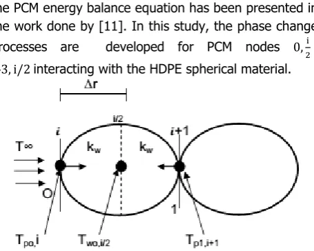
the PCM energy balance equation has been presented in the work done by [11]. In this study, the phase change processes are developed for PCM nodes 0,i
2
43, i/2 interacting with the HDPE spherical material.
Figure 7: Energy balance analysis of paraffin wax about center nodes 0, i/2 - 43, 𝑖/2, Source: [11]
The applicable energy equation as presented in [11] can be expressed as:
ℓwCpwAs
∂Tw
∂t = ∅ + kw
r2 As
∂ ∂r
r2∂(T
p0− Tw0,i/2)
∂r
+ kw r2 As
∂ ∂r
r2∂(T
p1− Tw0,i/2)
∂r
+ As∂r (64)
Applying the assumptions simplifies equation (64) and yields;
ℓwCpwAs
∂Tw
∂t = kw
r As
∂2(r(𝑇
𝑝0− Tw0,i/2))
∂r2
+ kw r As
∂2(r(T
p1− Tw0,i/2))
∂r2
+ As∂r (65)
Initial Conditions: Paraffin wax capsule;
Tw (rh,0)= Twinitial= Tp initial (66) Tw (r0,0)= Twinital= Tp intial (67)
Tw (rh
2,0)= Twinital= Tp initial (68)
Boundary Conditions:
Tw (r0,t)= −
hw
kw
[Tp(0,t)− Tw(r0
2,t)] (69)
Tw (rh,t)= −
hw
kw[Tp(43,t)− Tw(r2h,t)] (70)
To simplify the governing equation (65) for a suitable application of numerical approach, the following applicable dimensionless parameters are defined.
r∗= r
rh
, τ∗= t
t0
, θ = T − Tw Tp− Tw
(71)
According to [11], substituting Tw= Tp0− Tw0,i/2 and
Tp= Tp1− Tw0,i/2 with the dimensionless parameters into equation (65) gives
ℓwCpwAst0r∗rh
∂Tw
∂τ∗
= kwAst0
∂(T − Tw) + Tp
∂r∗∂θ
+ kwAst0r∗rh
∂(T − Tw) + Tw
∂r∗∂θ
+ Ast0r∗r
h∂r (72)
Dividing through by Ast0r∗r h gives
ℓwCpw
∂Tw
∂τ∗ =
kw
r∗r h
∂(T − Tw) + Tp
∂r∗∂θ +
kw
r∗r h
∂(T − Tw) + Tw
∂θ
+ ∂r r∗r h
(73)
Dividing equation (73) through by kw and multiplying the
solution by ∝w= kw
ℓwCpw gives:
∂Tw
∂τ∗ =
∝w
r∗r h
∂(T − Tw) + Tp
∂r∗∂θ +
∝w
r∗r h
∂(T − Tw) + Tw
∂r∗∂θ
+∝w
∂r r∗r h
(74)
By order of magnitude analysis of equation (74), both terms in the RHS are compared to have about the same magnitude, hence we have no justification to neglect one in preference to the other, hence both terms are retained [11].
Substituting Tw= Tp0− Tw0,i/2 , Tp= Tp1− Tw0,i/2 and
θ = T−Tw
Tp−Tw back to equation (74) yields
∂Tw
∂τ∗ =
∝w
r∗r h
∂(Tp0− Tw0,i/2) ∂r∗ +
∝w
r∗r h
∂(Tp1− Tw0,i/2) ∂r∗
+∝w
∂r r∗r h
(75)
Multiplying through by r∗rh
∝w gives
r∗r h
∝w
∂Tw ∂τ∗ =
∂(Tp0− Tw0,i/2)
∂r∗ +
∂(Tp1− Tw0,i/2)
∂r∗
+ ∂r (76)
Equation (76) is multiplied by ∝w= kw
ℓwCpw ,where r
∗= r rh to yield
r ∂Tw ∂τ∗ =
kw ℓwCpw
∂(Tp0− Tw0,i/2)
∂r∗ +
kw ℓwCpw
∂(Tp1− Tw0,i/2)
∂r∗
+ kw ℓwCpw
∂r (77)
Rearranging equation (77) gives
kw
ℓwCpw
∂(Tp0− Tw0,i/2)
∂r∗ +
kw
ℓwCpw
∂(Tp1− Tw0,i/2)
∂r∗
=r ∂Tw ∂τ∗ −
kw
ℓwCpw∂r (78)
Multiplying equation (79) by 𝜕r∗ gives
kw
ℓwCpw(Tp0− Tw0,i/2) +
kw
ℓwCpw(Tp1− Tw0,i/2)
=∂
2T wr. r∗
∂τ∗ −
kw∂r𝜕r∗
ℓwCpw
(79)
kw
ℓwCpw
(Tpo,in − T
wo,i/2n ) +
kw
ℓwCpw
(Tp1,i+1n − T wo,i/2n )
= Two,i/2
n+1 − T wo,i/2n
∆t ∆r
2 −𝑘𝑤∆r 2
ℓwCpw
(80)
Collecting like terms and multiplying through by ℓwCpw
𝑘𝑤 gives
Tpo,in − 2 Two,i 2 n + T
p1,i+1n
= ℓwCpw∆r
2
kw∆t (Two,2i n+1− T
wo,2i n )
− ∆r2 (81)
Further rearranging gives
Tpo,in − 2 T wo,2i
n + T
p1,i+1n + ∆r2
= ℓwCpw∆r
2
kw∆t (Two,2i n+1− T
wo,2i n ) (82)
Hence, equation (82) becomes
Tpo,in − 2 T wo,2i n + T
p1,i+1n + ∆r2
= ∆r
2
αw∆t (Two,2i n+1− T
wo,2i
n ) (83)
Multiplying equation (83) by αw∆t
∆r2 gives
αw∆t ∆r2 Tpo,in −
2αw∆t ∆r2 Two,i
2
n + αw∆t
∆r2 Tp1,i+1n + αw∆t
= T
wo,2i n+1− T
wo,2i
n (84)
Rearranging equation (84) gives
Two,i/2n+1 − T wo,2i
n = αw∆t
∆r2 Tpo,in −
2αw∆t ∆r2 Two,i
2 n
+ αw∆t
∆r2 Tp1,i+1n + αw∆t (85)
Where Fo= αw∆t
∆r2 is the Fourier number so that equation (85) becomes:
Fo (Tpo,in + Tp1,i+1n + αw∆t) + (1 − 2Fo) Two,i/2 n
= Two,i/2 n+1 (86)
Rearranging equation (86) gives
Two,i/2 n+1 = F
o (Tpo,in + Tp,i+1n + αw∆t)
+ (1 − 2Fo) Two,i/2 n (87)
Applying the stability criterion to equation (87), requires that the coefficient Two,i/2 n be greater than or equal to zero
so that ∆𝑡 – simulation time interval is selected to be well
within the stability limit which corresponds to the value of Fo [11].
(1 − 2Fo)Fo≥ O; Fo≤
1
2 ; ∆t = Fo∆r2
αw
; Fo=
αw∆t
∆r2
= 0.49 (88)
Substituting parameters for ∆r2, Fo and αw for
convergence and stability of the numerical results, the minimum permissible value for the computation time interval is Δt ≈ 1hr. By substituting Fo into equation (87)
gives
Two,i/2 n+1 = 0.49 (T
po,in + Tp1,i+1n +
kw
ℓwCpw
∆t)
+ 0.02 Two,i/2 n (89)
Equation (88) is the numerical model used to predict the phase change phenomenon of paraffin wax at nodes
0, i/2-43, i/2 which interacts with the HDPE capsule wall.
The model can be written at new time steps forming a set of N-algebraic linear equations solvable using MATLAB [11].
Node 0,i
2:
Two,i/2 n+1 = 0.49 (T
Po,i n + TP1,i+1 n + kw
ℓwCpw∆t) + 0. 02 Two,i/2
n
Two,i/2 n+2 = 0.49 (T
Po,i n+1+ TPo,i n+1+ kw
ℓwCpw∆t) + 0. 02 Two,i/2
n
Two,i/2 n+∞ = 0.49 (T Po,i
n+(∞−1)
+ TPo,i n+(∞−1)+ kw
ℓwCpw∆t) +
0. 02 Two,i/2 n+(∞−1)
Node 0,i
2 − 43, i 2 :
Two,i/2 n+1 = 0.49 (T
P1,i+1 n + TP2,i+2 n + kw
ℓwCpw∆t) +
0. 02 Tw1,i/2 n
Tw2,i/2 n+1 = 0.49 (T
P2,i+2 n + TP3,i+3 n + kw
ℓwCpw∆t) +
0. 02 Tw2,i/2 n
Tw43,i/2 n+1 = 0.49 (T
P43,i+43 n + TP44,i n + kw
ℓwCpw∆t) +
0. 02 Tw43,i/2 n
Cpw is the specific heat capacity of the paraffin wax with
melting and solidification boundary conditions stated as follows;
Cpw (solid) =
2kJ
kgK ; Two,i/2
n < 21°C
Cpw (solid−liquid) =
18kJ
kg K ; 23°C ≤ Two,i/2
n ≤ 25°C
Cpw(liquid) = 3.2KJ
kgK ; Two,i/2
n > 25°C
5. RESULTS AND DISCUSSION
The thermal performance of the developed numerical models for the paraffin wax and HDPE materials is dependent mainly on the Fourier number, Fo which
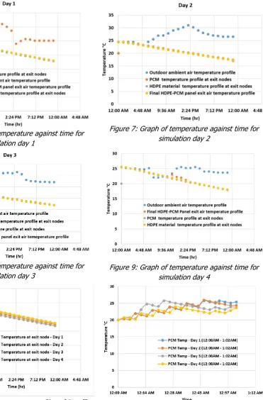
steel walls, the HDPE-PCM panel medium can effectively cool the indoor space of the conex envelope. Figure 6 - 9 are graphical representations of data in table 3 and noticeable similarity exist between the HDPE material temperature at exit nodes and the HDPE-PCM panel outlet air temperature. The HDPE-PCM panel outlet air temperature is observed to maintain values that do not decrease beyond the HDPE material and paraffin wax temperatures which entirely validates the first law of thermodynamics of thermal systems. Figure 10 presents the variations in the PCM temperature due to the varying surrounding ambient temperature passing through the conduit of the HDPE-PCM panel unit. Figure 10 and 11 show the PCM experiencing solid-solid/melting phase changes from 12am – 1am. This melting period accounts for latent heat storage operation between 23-24°C. It is
recommended that a CFD software is used for this simulation to accurately capture visibly the physical and thermal features of the solid – liquid boundary phase change domain in a post process simulation procedure. In Figure 10, the temperature drop in the paraffin wax and HDPE material at exit nodes is consistent from 1am-11pm irrespective of the fluctuating outdoor air
temperature. This is because of the
discharge/solidification phase of the PCM for which the discharged heat is shielded from the air flow during the period. The effect of the convective heat transfer hf of
the simulated air from the high pressure axial flow fan, is consequent on the air flowing throughout the HDPE-PCM panel system. This further causes a drop in the air temperature, leaving the conduit of the HDPE-PCM panel unit into the indoor space of the conex envelope.
Table 3: PCM (Paraffin wax), HDPE-PCM panel air inlet and exit temperatures for Day 1-4
Time
Tw, oC
for Day 1 PCM in
exit capsul
es
Tf, oC
for Day 1 (Panel
Inlet Air)
Tf, oC
for Day 1 (Panel
outlet Air)
Tw, oC
for Day 2 PCM in
exit capsul
es
Tf, oC
for Day 2(Pane
l Inlet Air)
Tf, oC
for Day 2 (Panel
outlet Air)
Tw, oC
for Day 3 PCM in
exit capsul
es
Tf, oC
for Day 3(Pane
l Inlet Air)
Tf, oC
for Day 3 (Panel
outlet Air)
Tw, oC
for Day 4 PCM in
exit capsul
es
Tf, oC
for Day 4(Pane
l Inlet Air)
Tf, oC
for Day 4 (Panel
outlet Air)
12am 20.0 25.5 25.4 20.0 24.5 24.4 20.0 23.8 23.7 20.0 25.5* 25.4
1am 25.3 25.2 25.4 24.3 24.5 24.4 23.7 23.6 23.7 25.3 25.2 25.4
2am 25.2 25.0 25.0 24.2 24.4 24.0 23.5 23.6 23.3 25.0 25.0 25.0
3am 24.9 25.0 24.8 23.9 24.4 23.8 23.2 23.8 23.1 24.7 25.0 24.8
4am 24.5 25.0 24.3 23.6 23.7 23.4 22.9 23.5 22.7 24.3 24.7 24.3
5am 24.2 25.2 24.0 23.2 23.2 23.1 22.6 23.5 22.4 23.9 24.7 24.0
6am 23.8 25.5 23.6 22.9 24.5 22.7 22.2 23.2 22.0 23.5 25.1 23.6
7am 23.5 26.5 23.3 22.6 25.5 22.4 21.9 24.2 21.8 23.2 22.1 23.3
8am 23.1 28.5 22.9 22.2 26.9 22.0 21.6 26.5 21.4 22.8 22.0 22.9
9am 22.4 28.5 22.6 21.9 27.0 21.7 21.2 28.6 21.1 22.5 22.3 22.6
10am 22.1 29.9 22.2 21.5 27.8 21.3 20.9 29.0 20.7 22.1 22.4 22.2
11am 21.7 30.0 21.9 21.2 29.0 21.0 20.6 29.9 20.4 21.7 23.4 22.9
12noon 21.4 31.0* 21.5 20.9 29.5 20.7 20.3 31.0 20.1 21.4 25.0 22.2
1pm 21.0 30.0 21.2 20.5 30.2 20.4 19.9 31.2 19.8 21.1 25.5* 21.9
2pm 20.7 28.6 20.8 20.2 31.0* 20.0 19.6 31.0 19.4 20.7 25.2 21.2
3pm 20.4 24.0 20.5 19.9 30.2 19.7 19.3 31.5* 19.2 20.4 25.2 20.5
4pm 20.0 25.0 20.2 19.6 29.0 19.4 19.0 30.6 18.8 20.1 25.5 20.2
5pm 19.7 25.6 19.9 19.2 28.0 19.1 18.7 28.0 18.5 19.7 25.0 19.9
6pm 19.4 25.5 19.5 18.9 27.5 18.8 18.4 27.5 18.2 19.4 24.0 19.5
7pm 19.1 25.1 19.2 18.6 27.0 18.5 18.1 27.4 17.9 19.1 24.0 19.2
8pm 18.7 25.1 18.9 18.3 26.8 18.1 17.8 27.2 17.6 18.8 23.8 18.9
9pm 18.4 25.1 18.6 18.0 26.5 17.9 17.5 27.2 17.4 18.5 23.6 18.6
10pm 18.1 25.1 18.3 17.7 26.5 17.6 17.2 27.0 17.1 18.2 23.6 18.3
11pm 17.8 25.1 18.0 17.4 26.5 17.3 16.9 27.0 16.8 17.9 23.6 18.0
Avg. daily peak
Temp °C 31.0 31.0 31.5 25.5 29.7
Avg
Figure 6: Graph of temperature against time for simulation day 1
Figure 7: Graph of temperature against time for simulation day 2
Figure 8: Graph of temperature against time for
simulation day 3 Figure 9: Graph of temperature against time for simulation day 4
Figure 10: Graph of Temperature profiles of Paraffin
wax at HDPE-PCM panel exit nodes Figure 11: Graph of latent heat energy storage period of the PCM for simulation day 1-4
5. CONCLUSION
The author recommends that actual experiments and CFD analysis be conducted to validate the results obtained in this study. Furthermore, to ensure a completely green and passive cooling system, solar
causing significant ambient temperature depressions of 7.1 – 10.2oC at the outlet duct of the HDPE-PCM
panel system. Reverse suction DC fan(s) for indoor air quality recirculation and removal can be placed at strategic points on the steel walls, the HDPE-PCM panel medium can effectively cool the indoor space of the shipping container home.
6. NOMENCLATURE
Tf− Temperature of air in HDPE-PCM panel
medium, °C
Tw− Temperature of PCM(Paraffin wax) , °C
Tp− Temperature of HDPE capsule material, °C
Ts− Surface node temperature, °C
Tr− Radiative temperature, °C
To− Estimated capsule outlet temperature, °C
T∞− Hourly outdoor ambiemt air temperature , °C
T∞mid− Mid-day outdoor ambient air
temperature, °C
T∞peak − Peak daily ambient temperature, °C
Tlm− Log mean temperature, °C
kp−Thermal conductivity of HDPE panel material,
W/mK
kf− Thermal conductivity of air, W/mK
kw− Thermal conductivity of paraffin wax, W/mK
∅− Heat generation, W/m3
ℓp− Density of HDPE panel material, kg/m3
ℓw− Density of PCM, kg/m3
Cpp−Specific heat capacity of HDPE material, J/kg K
Cpf− Specific heat capacity of air, J/kg K
Cpw−Specific heat capacity of PCM, J/kg K
As− External surface area of each capsule, m2
Ap− External surface area of HDPE-PCM panel, m2
Apt− Area of HDPE-PCM panel with porosity, m2
AD− Axial fan duct area, m2
hw− Convective heat transfer coefficient of PCM in
liquid phase, W/m2K
hf− Convective heat transfer coefficient of air,
W/m2K
hr− Radiative heat transfer coefficient, W/m2K
r∗− Dimensionless distance from the centre of
HDPE-PCM panel
rh − Diametral distance at end length of HDPE-PCM
panel / panel outlet capsules, m
r − Diametral distance of HDPE-PCM capsule, m r0− Diametral distance at start length of HDPE-PCM
panel/panel inlet capsules, m
r1 − Diametral distance at end length HDPE-PCM
first row capsules, m
∆r − Elemental diameter of HDPE-PCM capsule, m
i/2 − Node notation at mid-point of HDPE-PCM
capsule
τ∗−Dimensionless time
θ − Dimensionless temperature ∆t−Computational time interval
∝p− Thermal diffusivity of HDPE-PCM, m2/s
∝w− Thermal diffusivity of PCM, m2/s
Nu− Nusselt number
ε− HDPE-PCM panel porosity Re − Reynolds number Pr− Prandtl number
Fo− Fourier number
Qv−Volumetric mass flow rate of air, m3/s
h− HDPE-PCM panel height/ length of the axial air
flow region, m
Vp − Volume of paraffin wax storage in the HDPE
capsules, m3
Vo− Volume of the void fraction in the HDPE-PCM
panel medium
R−Radius of HDPE capsule, m
tp− Thickness of the HDPE shell coating of
capsules, m
ms − Mass of a single capsule, kg
mp− Mass of the HDPE-PCM panel medium, kg
Nc– Total number of HDPE capsules packed in the
panel medium
Ny− Number of HDPE capsules packed in the y-axis
Nx− Number of HDPE capsules packed in the x-axis
q − Heat transfer rate, W
Є − HDPE capsule material emissivity б −Stefan boltzman constant, W/m2K4
𝑥 − Space increment along HDPE-PCM panel height
per element, m
Subscripts
p− HDPE panel material f− flowing air
w − Paraffin wax x−x axis
y − y axis
7. REFERENCES
[1].Hanan, M. T. Using passive cooling strategies to improve thermal performance and reduce energy consumption of residential buildings in U.A.E. buildings, Frontiers in Architectural Research
3(2), 154-165, 2014.
[2].Inusa M. & Alibaba, H.Z. Application of Passive Cooling Techniques in Residential Buildings; A Case Study of Northern Nigeria. International Journal of Engineering Research and Application
7(1), 22-30, 2017.
[3].Dincer, I. & Rosen, M. A. Thermal energy storage systems and applications. United Kingdom, John Wiley and Sons Ltd, 7-599, 2011.
[4].Mohdlsa, M. H., Zhao, X. & Yoshino, H. Preliminary study of passive cooling strategy using a combination of PCM and copper foam to increase thermal heat storage in building facade.
Journal of Sustainability, 2, 2071-2381, 2010. [5].Arkar, C. & Medved, S. Free cooling of a building
using PCM heat storage integrated into the ventilation system, Solar Energy 81, 1078-1087,2007.
[6].Zhang, Y., Zhou, G., Lin, K., Zhang, Q. & Di, D. Application of latent heat thermal energy storage in buildings; state of the art and outlook, Building and Environment 42, 2197-2209, 2007.
[7].Stritith, U. & Butala, V. Energy saving in building with PCM cold storage, International Journal of Energy Research 31, 1532-1544, 2007.
[8].Medina, M. A., King, J. B. & Zhang, M. On the heat transfer rate reduction of structural insulated panels (SIPs) out-filled with phase change materials (PCMs), Energy 33, 667-678, 2008.
[9].Medved, S. & Arkar, C. Correlation between the local climate and the free-cooling potential of
latent heat storage, Energy and Buildings 40, 429-437, 2008.
[10]. Lamberg, P., Lehtiniemi, R. & Henell, A. Numerical and experimental investigation of melting and freezing processes in phase change material storage. International Journal of Thermal Science, 43, 277-287, 2004.
[11]. Udosen, A. N,. Transient numerical models for predicting the performance of encapsulated PCM under varying ambient temperatures for cooling application. International Journal of Scientific & Engineering Research, 9(3), 253-260, 2018.
[12]. Enibe, S. O. Thermal analysis of a natural circulation solar air heater with phase change material energy storage. Renewable Energy,
28(14), 2269–2299, 2003.
[13]. Johannes, K., Borderon, J., Virgone, J., Cantin, R., & Kuznik, F.. Numerical analysis of the thermal comfort in a retrofitted family house using a PCM/Air Heat Exchanger-System. 12th Conference of International Building Performance Simulation Association, Sydney, 720-726, 2011. [14]. Singh, R., Saini, R., & Saini, J. Simulated
performance of packed bed solar energy storage system having storage material elements of large size (Part I). The OpenFuels and Energy Science Journal, I, 91-96, 2008.
[15]. Incropera, De Witt, Bergman, T. & Lavine, A..
Fundamentals of heat and mass transfer. Sixth Edition. Wiley Companies, 2011.
[16]. Udosen, A. N, Modeling of the performance of Micro-Encapsulated Phase Change Material for Maintenance of Comfortable Space Temperature.
![Figure 5: surface temperature for nodes 0 – 44 at steady state, Energy balance analysis about HDPE shell Source: [16]](https://thumb-us.123doks.com/thumbv2/123dok_us/9991885.1987156/6.595.309.534.547.636/figure-surface-temperature-steady-energy-balance-analysis-source.webp)