Emails: [email protected]; [email protected] b
Dept. of Electrical/Electronic Engineering, Enugu State University of Science and Technology Owerri, Nigeria.
Abstract
An improved version of the Static-Threshold-Limited On-Demand Guaranteed Service Timed-Token (STOGSTT) Media Access Control (MAC) protocol for channel capacity allocation to the asynchronous traffic in Multiservice Local Area Network (MLANs) was developed and analyzed. STLODGSTT protocol uses static value of threshold bandwidth to allocate available bandwidth to the asynchronous traffic, as such, the throughput of STLODGSTT protocol drops significantly un-der non-uniform heavy load of asynchronous traffic. The DTLTT protocol dynamically adjusts the threshold bandwidth in response to the variations in the load distribution of the asynchronous traffic. In view of this dynamic mechanism, under various load distributions of the asynchronous traffic, the DTLTT protocol maintains higher throughput than the STLODGSTT protocol. The improvement is demonstrated through analytical computations and simulation results.
Keywords: multi-access, multiservice, network, synchronous, asynchronous, traffic, timed-token
1. Introduction
Nowadays, efficient support for both time-critical and best-effort traffic in the same Local Area Net-works (LANs) is essential [1, 2] The MAC protocols for such MLANs must provide not only bounded mes-sage transmission time, as required by the hard and soft real-time tasks, but also high throughput, as de-manded by non real-time tasks that relies on best-effort services [3, 4, 5, 6]. An attractive MAC ap-proach for such networks is the timed-token protocol. Consequently, the timed-token protocol has been in-corporated into several high-bandwidth network stan-dards [7], such as, IEEE802.4 Token Bus LAN [8] , Fiber Distributed Data Interface (FDDI) [9, 10, 11, 12, 13 ] SAFENET [14], Manufacturing Automation Protocol (MAP) [15], High-Speed Ring Bus [16], in PROFIBUS [17], and in wireless networks [18, 19, 20]. The STOGSTT protocol is a version of the timed-token protocol developed to improve the communi-cation services provided by the existing timed-token protocols [21]. Nevertheless, the throughput of the STOGSTT protocol drops whenever some of the nodes do not have asynchronous traffic to transmit. That means, if n is the number of nodes that are heav-ily loaded with asynchronous traffic, where 1 ≤n ≤
N, the throughput of the STOGSTT protocol drops
whenever n < N , but it attains to its maximum throughput when n = N. The problem is solved in the DTLTT protocol developed in this paper. The DTLTT protocol dynamically adjust the value of the threshold bandwidth used in allocating available bandwidth to the n heavily loaded nodes. With this dynamic mechanism, the DTLTT maintains higher throughput irrespective of the variations in the dis-tribution of asynchronous traffic in the network.
The rest of the paper is organized as follows; the network model , message model and timed token pro-tocol parameters are presented in Section 2 along with a review of the STOGSTT protocol. The DTLTT protocol is presented and analyzed in Section 3. In section 4, the simulation and analytical computation results are presented and discussed. Finally, conclud-ing remarks and recommendations for further studies are stated in Section 5.
2. Network Characteristics
2.1. Network Model
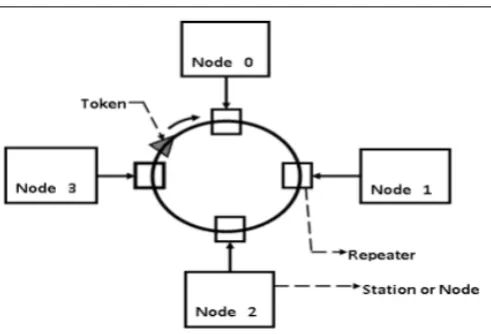
2.1.1. Token ring network model
The study considered a token ring or logical ring network consisting ofN nodes (or stations), as shown in Fig 1. Each node has a unique number in the range
Figure 1: A 4-station token ring network.
0, 1, 2, . . . , N −1. In addition, each node is con-nected to two other neighbouring nodes by unidirec-tional point-to-point media that form a single closed path. For each nodei, the next node along the unidi-rectional medium is station (i+ 1) or more appropri-ately node (i+ 1) modN.
2.1.2. Logical ring network model
Similar network model can also exist on a logical ring network otherwise known as token bus network as, as shown in Fig 2. In this case, we consider a bus withN nodes connected to form a unidirectional log-ical ring on the bus. Each node has a unique number in the range 0, 1, 2,. . . , N−1. In addition, each node has two other neighbouring nodes. For each node i, the next node along the unidirectional logical ring is station (i+ 1) or more appropriately node (i+ 1) mod N.
2.1.3. The token and ring latency
A special bit pattern called the token circulates around the ring (logical ring or token ring) from node i to nodes i+ 1, i+ 2, . . . until node i+ (N −1), then to nodesi, i+ 1, i+ 2, . . ., helping to determine which node should send a frame of message among the contending nodes.
Definition: Let wi denote the latency or
walk-time between a nodeiand its upstream neighbor node (i+ 1). wi can also be defined as the time needed to
transmit the token between nodes, including the over-head introduced by the protocol [2]. Then,
W =
N−1
X
i
wi (1)
The ring latency, W denotes the token walk time around the ring when none of the nodes in the net-work disturb it [9, 22].
2.2. Message Model
Messages generated in the system at run time may be classified as either synchronous messages or asynchronous messages. In the following discus-sion it is assumed that there is one stream of syn-chronous messages on each node [23, 9]. It is also assumed that the network is free from hardware or software failures. Hence, in the N-node ring, the synchronous message set, M, consist of N streams of synchronous messages;s0, s1, s2, . . . , sN−1 where,
M ={s0, s1, s2, . . . , sN−1}. The synchronous
mes-sage stream,si at nodeiis given assi={Pi, Ci, Di}
and shown in Fig 3 where:
• Message length,Ciis the maximum amount of
time required to transmit a stream message. This includes the time required to transmit both the payload data and message headers.
• Period Length,Pi is the minimum inter-arrival
period between consecutive messages in stream, si at node i. If the first message of node i is
put in the transmission queue at time ti,1 , then
the j-th message in streamsi will arrive at time ti,j=ti,1+ (j−1)Pi, wherej >1. For instance,
if the first message arrives at time t, then the second message will arrive att+Piand the third
message will arrive at t+ 2Pi as shown in Fig 2.
• Message Deadline,Di, is the relative deadline
associated with messages in stream si, that is,
the maximum amount of time that can elapse be-tween a message arrival and the completion of its transmission. Thus, the transmission of the j-th message in stream si that arrives atti,j must be
completed no later than ti,j+Di, which is the
message’s absolute deadline. Again, as an exam-ple, if the first message in the message stream,si
arrives at timet, then it must be transmitted not later thant+Di, as shown in Fig 2.
2.3. The timed-token medium access control (MAC) protocol parameters
The parameters of the timed-token as presented in [21] include the following:
a) Target Token Rotation Time, (TTRT): TTRT is the time needed by the token to complete an en-tire round-trip of the network. The value of TTRT is denoted asτ.
b) Synchronous Capacity of Node i (Hi): Hi
rep-resents the maximum time for which a station, i is allowed to transmit synchronous messages during ev-ery token receipt. Then according to [21],
H0+H1+. . .+HN−1=
i=N−1
X
i=0
(Hi)
!
=H (2)
Figure 2: A 7-station token bus network.
H+W =T (4)
A=τ+T (5)
where A be defined as the total time units available to the asynchronous traffic in every cycle.
Constraints:
For proper operation of the timed-token protocol, the choice of values for theτ andT parameters must sat-isfy the Protocol Constraint and the Deadline Con-straint which according to [21] is given as,
τ≤ min
i=0,1,...,N−1(Di) (6)
c) Token Rotation Timer of Node i (T RTi): T RTi
is the cycle length or the time between two consecutive token receipts at nodei.
d) The Unused Synchronous Bandwidth, (ε): Ac-cording to [21]
hi =Hi−εi (7)
where hi denotes the used portion of Hi and εi the
unused portion of Hi time units reserved for the
syn-chronous traffic in nodei(wherehi≤Hi). Then, for
a system that is lightly loaded with synchronous traf-fic, out of the Hi time units, only hi time units are
used in nodeileavingεi time units unused
εi+εi+. . .+εi=ε (8)
e) An Asynchronous-Limit Variable of Node i
(T HTi): T HTi is used to control the amount of time
for which nodeican transmit asynchronous messages [21].
f) The Number of Heavily Loaded Nodes in a Net-work (n): n denotes the number of nodes that are heavily loaded with asynchronous traffic out of theN nodes in the network. In uniformly heavily loaded network n=N, however, in a non-uniformly heavily loaded network 1≤n < N
2.4. Review of STLODGSTT protocol
Generally, in the timed token protocols, there is un-allocated bandwidth per cycle, given as A = τ −T
(which is the same as, A = τ −H −W). The ST-LODGSTT allocates this A bandwidth to the asyn-chronous traffic using its static threshold limited best-effort bandwidth allocation mechanism. Specifically, the STLODGSTT protocol usesai time units in each
node i, for the transmission of asynchronous traffic, where ai = max(0, τ −ε−(ti −ti−N)) +AT, and AT = τ−NT [21]. According to [21], in each cycle, the
total time units used for the transmission of asyn-chronous traffic is given as Pi=N−1
1=0 (ai) ≤ A time
units (whereA=τ−H−W). At its stable state, ST-LODGSTT allocates AT time units to each node for
its asynchronous traffic. Hence, at its best, the ST-LODGSTT can have an average ofn∗(τ−NT) time units per cycle for its asynchronous traffic; where n is the number of nodes with heavy load of asynchronous traf-fic. When n < N, the throughput of STLODGSTT per cycle for the asynchronous traffic drops. In or-der to overcome this constraint on the STLODGSTT, the DTLTT protocol is developed in this paper to dy-namically determinenand hence recalculatesAT with
respect tonrather thanN. Thus, in the DTLTT pro-tocol, AT = τ−nT. In this case,n∗(τ−NT) will always
remain at its maximum value ofτ−T.
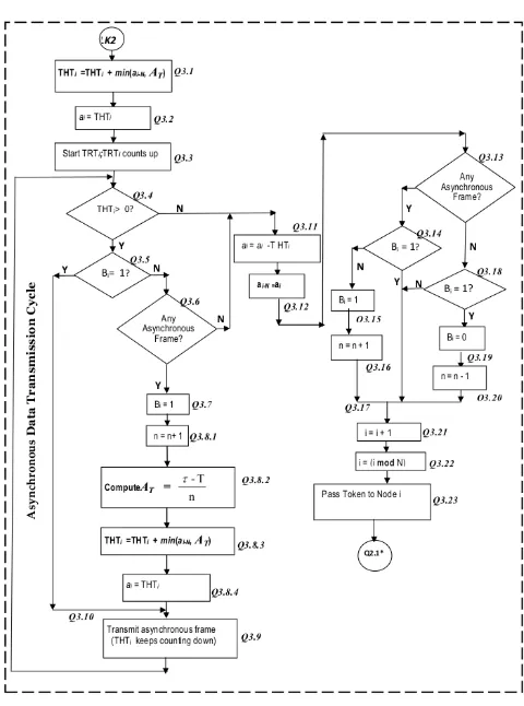
3. The DTLTT MAC Protocol
The flowchart of the DTLTT protocol is presented in Fig 4 while the detailed algorithm is given here as
Protocol Q MAC Algorithm. The algorithm is adapted from that of the STOGSTT Protocol [21]. At each to-ken receipt the DTLTT algorithm determines n, the number of nodes with heavy load of asynchronous traf-fic and hence recalculates AT = τ−nT. The updated
value ofAT is then used in the allocation of available
bandwidth to the asynchronous traffic among the n nodes that are heavily loaded with asynchronous traf-fic in that given cycle.
3.1. Outline of the DTLTT MAC Algorithm: Protocol Q
Q1: Initialization Cycle: Q1.1Define TTRT (that isτ) andN
Q1.2Define wi fori= 0,1, . . . N−1.
Figure 3: Model for the synchronous (or real-time) message stream,Siin node 1 [21].
Q1.3DefineHi fori= 0,1, . . . N−1.
Q1.4Initializeεi=Hiandhi= 0 fori= 0, 1, . . . N− 1.
Q1.5Initializeai−N = 0 fori= 0,1, . . . N−1.
Q1.6Computeε=
i=N−1
X
i=0
(εi) =H.
Q1.7ComputeT =
i=N−1
X
i=0
(Hi+wi)
!
;
Q1.8InitializeBi= 1 for i= 0,1, . . . N−1. Q1.9n=N.
Q1.10 ComputeAT = τ−nT.
Q1.11 Initialize Token rotation timer (T RTi) Timer. Q1.11.1 i= 0. Q1.11.2 T RTi = 0. Q1.11.3Start T RTi;T RTi Counts up. Q1.11.4i=i+ 1. Q1.11.5
Pass the Token to Node i+ 1. Q1.11.6IF (i < N) Then Goto Step Q1.11.2 Else Goto StepQ2.1 End if.
Q2: Data Transmission Cycle,
I: Transmission Of Synchronous Frames Q2.1Check Frames that arrives at Nodei.
Q2.2IF (Frames is Token) Then Goto StepQ2.5Else Goto StepQ2.3End if.
Q2.3Process Frame (Store, Ignore, etc.)
Q2.4Goto StepQ2.1.
Q2.5T HTi= max(T T RT−ε−T RTi,0). Q2.6ε0=ε−εI.
Q2.7.1T RTi = 0. Q2.7.2StartT RTi Q2.7.3T RTi
counts up.
Q2.8 IF (T RTi ≤ Hi) Then Goto Step Q2.9 Else
Goto StepQ2.12End if.
Q2.9 IF (Synchronous Data Available) Then Goto StepQ2.10 Else Goto StepQ2.11 End if.
Q2.10 Transmit Synchronous Frames.
Q2.11 Goto StepQ2.8.
Q2.12 hi =T RTi. Q2.13 εi=Hi+hi.
Q2.14 ε=ε0+εI (GotoQ3.1).
Q3: Data Transmission Cycle,
Part i: Transmission Of Asynchronous Frames Q3.1T HTi =T HTi+ min(a1−N, AT).
Q3.2ai=T HTi.
Q3.3StartT HTi,T HTi counts down.
Q3.4 IF (T HTi > 0) Then Goto Step Q3.5 Else
Goto StepQ3.11End if.
Q3.5 IF (Bi = 1) Then Goto Step Q3.9 Else Goto
StepQ3.6End if.
Q3.6 IF (Asynchronous Data Available) Then Goto StepQ3.7Else Goto Step Q3.11End if.
Q3.7Bi= 1.
Q3.8.1 n = n+ 1. Q3.8.2 Compute AT = τ−nT. Q3.8.3 T HTi = T HTi + min(ai−N, AT). Q3.8.4 ai=T HTi.
(a) Continues on next page.
Figure 4: Flowchart of DTLTT protocol.
(b) Continued from previous page.
Q3.17 Goto StepQ3.21.
Q3.18IF (Bi= 1) Then Goto StepQ3.19Else Goto
StepQ3.21 End if.
Q3.19 Bi= 0. Q3.20 n=n−1.
Q3.21 i=i+ 1.
Q3.22 i= (i modN).
Q3.23 Pass the Token to Nodei(Goto Q2.1).
3.2. Analysis of the DTLTT MAC algorithm
According to the protocol operations in Q2.5 of Protocol Q MAC Algorithm in Section 3.1, when the token arrives at node i, thenT HTi is determined as,
T HTi≤max(0, T T RT−ε−T RTi)
for allT T RTi
(9)
According to the protocol operations in Q3.1 and
Q3.8.3of Protocol Q MAC Algorithm in Section 3.1, T HTiis updated as follows
T HTi=T HTi+ min(AT, ai−N) (10)
According to the protocol operations in Q3.2 and
Q3.8.4, ai is defined as; ai = T HTi; thus, from Eq
13a Which 13a?????
ai=T HTi+ min(AT, ai−N) (11)
Since only nnodes are heavily loaded, wheren≤N, some nodes may have no asynchronous frames to transmit; in that case,
ai= 0 (12)
Let ax represent those nodes that are heavily
loaded with asynchronous traffic, where, x∃n; x = 0,1, 2, . . . , n−1 and 1≤n ≤N. Let ay represent
those nodes that are not heavily loaded with asyn-chronous trafficy@nand y= 0,1, 2, . . . , n0. Where
n0 =N−n (13)
NowA=τ−T andAT = An; wherenis the number
of nodes that are heavily loaded with asynchronous traffic and 1 ≤n ≤N. For a system that is heavily loaded with asynchronous traffic, in every cycle, at least n nodes have as much asynchronous traffic as AT, such that when each of the n nodes transmits AT asynchronous frames in the cycle, a total of A
min(AT, ai−N) =AT; wherei∃n
Hence, from Eq13b Which 13b?????
ai ≤T HTi+AT; wherei∃n (14)
Similarly, for those nodes that are not heavily loaded with asynchronous traffic, ay = 0 and ai−N = ay,
then
ai−N = 0; wherei@n
Thus, for those nodes that are not heavily loaded with asynchronous traffic,
min(AT, ai−N) = 0; wherei@n
Hence, for those nodes that are not heavily loaded with asynchronous traffic
ai= 0; wherei@n (15)
For a system that is heavily loaded with asynchronous traffic, at least one node is heavily loaded with asyn-chronous traffic, hence, Eq13, Eq14 and Eq15,
ai≤max(0, T T RT−ε−T RTi) +AT (16)
IfT RTi is replaced withti−ti−N, andT T RT withτ
then, Eq16 gives;
ai≤τ−ε−(ti−ti−N) +AT whenτ−ε >(ti−ti−N)
or
ai=AT whenτ −ε= (ti−ti−N) (17)
Again, for a heavily loaded system, these give;
ai≤max(0, τ−−(ti−ti−N))+AT for alli >0 (18)
If the token reaches node i at time, ti, then the
to-ken will reach nodei+ 1 atti+1 after transmittinghi
time units of synchronous traffic and ai time units of
asynchronous traffic along with a token walk-time,wi.
Thus
ti+1≤ti+ai+hi+wi (19)
ti+1≤ti−N+AT+τ−ε+(σi−εi) for (ti−ti−N)< τ−
ti+1≤ti+AT+σi−εiforτ−ε= (ti−ti−N)< τ−
(20)
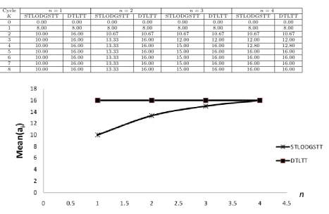
Table 1a: Mean(ai) for the STOGSTT and DTLTT protocols; whereH = 80,ε= 40 andn= 1, 2, 3, 4.
Cycle n= 1 n= 2 n= 3 n= 4
K STLODGSTT DTLTT STLODGSTT DTLTT STLODGSTT DTLTT STLODGSTT DTLTT
0 0.00 0.00 0.00 0.00 0.00 0.00 0.00 0.00
1 8.00 8.00 8.00 8.00 8.00 8.00 8.00 8.00
2 10.00 16.00 10.67 10.67 10.67 10.67 10.67 10.67
3 10.00 16.00 13.33 16.00 12.00 12.00 12.00 12.00
4 10.00 16.00 13.33 16.00 15.00 16.00 12.80 12.80
5 10.00 16.00 13.33 16.00 15.00 16.00 16.00 16.00
6 10.00 16.00 13.33 16.00 15.00 16.00 16.00 16.00
7 10.00 16.00 13.33 16.00 15.00 16.00 16.00 16.00
8 10.00 16.00 13.33 16.00 15.00 16.00 16.00 16.00
Figure 5: Variation of Mean(ai) with nfor the STOGSTT/DTLTT protocols, where H = 80 andε = 40; Data from
Table 1, CycleK= 10.
Table 1b: Steady state Mean(ai) for the STOGSTT and DTLTT protocols extracted from Table 1a ; for all cycle,K≥5.
n Mean(ai) for STOGSTT Mean(ai) for DTLTT
1 10 16
2 13.33 16
3 15 16
4 16 16
Then, combining these for a system that is heavily loaded gives
ti+1≤max(ti+AT, ti−N+AT+τ−ε)+(σi−εi) for alli≥0
(21) where σi−εi=σ(i modN)−ε(imodN).
Eq19 for ti+1 in the DTLTT protocol is the same
for ti+1 in the STOGSTT Protocol [21]. As such the
remaining set of steps for the analysis in [21] apply to the DTLTT protocol. The only difference between the remaining analytical expressions in the DTLTT protocol and that of STOGSTT Protocol in [21] is that whereasAT =bτ−nTc, in the DTLTT protocol; AT =
bτ−T
N c in the STOGSTT Protocol. Thus, following
the analysis in [21] , from Eq 21,
ti≤
1 +b i
N+ 1c
(τ−T) +b i
N+ 1cAT+
b i−1
N+ 1c(T−ε) +
j=(i−1) modN
X
j=0
(σj−εj)
(22)
and
tN k≤
1 +b i
N+ 1c
(τ−T)+
bn·K
N+ 1cAT +k(T−ε)
(23)
3.2.1. Upper Bound On Cycle Length,max(ti−ti−N)
Also, following the analysis in [21],
max(ti−ti−N) =τfor alli≥0and ε= 0 (24)
3.2.2. Average Cycle Length, (ˆc)
Let ˆcbe the Average Cycle Length, and from pro-tocolQ3.8.2
AT =b τ−T
Figure 6: Variation of Mean(T RTi) withn for the STOGSTT and DTLTT protocols, whereH = 80 andε= 40; Data
from Table 2, CycleK = 10.
Table 2b: Steady state Mean(T RTi) for the
STOGSTT and DTLTT protocols extracted from Ta-ble 2a for all cycle,K≥5.
n Mean(T RTi) for STOGSTT Mean(T RTi) for DTLTT
1 54 60
2 57.33 60
3 59 60
4 60 60
Then, from Eq23, ˆcis given as
ˆ
c≤limk→∞( tN k
k )≤ b n(τ−T)
n+1 c+b n(AT)
n+1 c+
(T−ε)
ˆ
c≤ bn(τ−T)
n+ 1 c+b τ−T
n+ 1c+ (T−ε) (26)
ˆ
c≤(τ−T) + (T−ε)
ˆ
c≤τ−ε (27)
These give the average cycle length for the DTLTT protocol under light load of synchronous traffic (where ε > 0) but with non uniform heavy load of asyn-chronous traffic. When ε= 0,
ˆ
c≤(τ−T) +T
ˆ
c≤τ (28)
These give the average cycle length for the DTLTT protocol under heavy load of synchronous traffic where ε = 0 but with non uniform heavy load of asyn-chronous traffic.
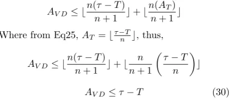
3.2.3. (Channel Capacity) Time Used By The Asyn-chronous Traffic Per Cycle,AV
LetAV denote the average (Channel Capacity) time
used by the asynchronous traffic per cycle in the DTLTT, then from Eq26
Av≤ b
n(τ−T) n+ 1 c+b
n(AT)
n+ 1 c (29)
Where from Eq25 AT =b(τ−nT)c. Eq29 gives the
av-erage time used by the asynchronous traffic per cycle irrespective of the load level of the synchronous traffic.
3.3. Comparison Of the Performance of The DTLTT Protocol and The STLODGSTT Protocol Under Non Uniform Heavy Load of Asynchronous Traffic. The Average Asynchronous Traffic Time Units Per Cycle (AV)
In this paper, it has been shown that for the DTLTT protocol, the average Asynchronous Traffic (Capac-ity) Time Units Per Cycle for the DTLTT under non
uniform heavy load of asynchronous traffic is given as AV D, where, from Eq 26 or Eq29,AV D =AV. Hence,
AV D ≤ b
n(τ−T) n+ 1 c+b
n(AT) n+ 1c
Where from Eq25, AT =bτ−nTc, thus,
AV D≤ b
n(τ−T) n+ 1 c+b
n n+ 1
τ−T
n
c
AV D ≤τ−T (30)
These give the average time used by the asynchronous traffic per cycle in the DTLTT irrespective of the load level of the synchronous traffic. On the other hand, it has been shown in [21], the average time used by the asynchronous traffic per cycle in the STLODGSTT protocol, is given asAV S, where
AV S≤ b
N(τ−T) N+ 1 c+b
N(AT)
N+ 1 c (31a)
With respect to Eq26a and Eq26b, under non uniform heavy load of asynchronous traffic, Eq31a gives
AV S ≤ b
n(τ−T) n+ 1 c+b
n(AT)
n+ 1c (31b)
Now , in the STLODGSTT protocol, irrespective of the load distribution of the asynchronous traffic,AT =
bτ−T
N c, thus, Eq31b gives
AV S ≤ b
n(τ−T) n+ 1 c+b
n n+ 1
τ
−T
N
c (31c)
For any given τ, T, N and n, AV D always exceeds AV S where,
AV D−AV S=bn(τ−T)
n+ 1
N−n
nN
c (32)
3.4. Simulation of Protocol Q
The simulation of the MAC algorithms for the DTLTT protocol (Protocol Q) was conducted with a program written with Visual Basic for Applications (VBA). The program runs in Microsoft Office Ex-cel 2007 environment. The following mathematical expressions will be used to compare the simulation results with the results obtained from the analytical computations. For the simulation results, if the values of N, n, T, τ and ε remain constant for at leastM consecutive cycles whereM N, then MEAN(T RTi)
approaches ˆc obtained from the analytical computa-tions where, MEAN(RTj,k] ) is given as
MEAN(T RTi) =
1 n+ 1
i=x+n X
i=x T RTi
!
forx > N
(33)
Table 3: Values of AV D−AV S based on simulation
and based on the analytic expression in Eq32b.
n Values of AVD based on analytic compu-tations Values of AVS based on analytic compu-tations
From Table 1b: Mean(ai) for the DTLTT -Mean(ai) for the STOGSTT based on simulation
Values of AVD - AVS based on analytic com-putations of Eq 32b
1 16.0 10.0 6.0 6.0
2 16.0 13.3 2.7 2.7
3 16.0 15.0 1.0 1.0
4 16.0 16.0 0.0 0.0
Similarly,
MEAN(ai) =
1
n+ 1
i=x+n X
i=x ai
!
forx > N (34)
The average values are considered as from cycleN+ 1 and the average values are taken for every set ofn+ 1 cycles.
The Maximum Cycle Length is MAX(T RTi) for all i≥0.
4. The protocols Simulation and Analytical Computation Results
4.1. The network and protocol parameters for the test
Consider a ring network with four stations (N= 4). The network uses the DTLTT and STOGSTT proto-cols for its MAC where the timed-token parameters are given as follows: T T RT =τ = 100, wi = 1 and Hi = 20 for all the nodes. With these given
parame-ters, then H = 4(20) = 80.
4.2. For the simulation
The simulation was performed for a 4-node network (that means, N = 4) . The network is non-uniformly heavily loaded with asynchronous traffic (that means, 1 ≤ n ≤ N) and also has about 50% (that means, ε= 0.5∗H) load level of the synchronous traffic. The simulation data captured are Mean(ai) (the Mean of
the time units allocated to the asynchronous traffic in every cycle) and Mean(T RTi) (the Mean of Token
Rotation Time in every cycle). The simulation results for DTLTT and STOGSTT protocols are shown in Table 1a, Table 1b, Table 2a, Table 2b, and Table 3, as well as in Fig 5 and Fig 6.
4.3. Protocols test results
Note: In Table 3, AV S is the same thing as
Mean(ai) for the STOGSTT and AV D is the same
thing as Mean(ai) for the DTLTT. AV S and AV D
are obtained from analytical computations whereas Mean(ai) for the two protocols are obtained from
expression in Eq30c asAV D =τ−T = 16 for all values
ofncorresponds with the values ofAV Dobtained from
the simulation results and shown in Table 1a and in Table 1b. These results indicate that the analytical expression effectively capture the performance of the DTLTT protocol (Protocol Q).
4.4.2. Comparison of the performance of the proto-cols: The average asynchronous traffic time units per cycle for the timely-token protocol, the STOGSTT protocol and the DTLTT protocol
From Table 1a, Table 1d, Table 3 and Fig 5, the Av-erage Asynchronous Traffic Time Units Per Cycle for the STOGSTT protocol increases as n increases from 1 to N . However, the Average Asynchronous Traffic Time Units Per Cycle for STOGSTT protocol trails behind that of the DTLTT Protocol . Specifically, as n increases from 1 to N, the Average Asynchronous Traffic Time Units Per Cycle for the DTLTT Protocol remains constant at the value of τ−T, which in the case of Table 1a, Table 1b and Table 3, isτ−T = 16. In all, the Average Asynchronous Traffic Time Units Per Cycle for the DTLTT Protocol is not affected by n, whereas in the STOGSTT protocol, their Average Asynchronous Traffic Time Units Per Cycle decreases as n decrease fromN to 1.
Also, the same argument applies to Mean(T RTi)
(that is, the Average Cycle Length) for the DTLTT and STOGSTT protocols, as can be seen from Table 2a, Table 2b, and Fig 6.
5. Conclusion and Recommendations
5.1. Conclusion
In this paper, DTLTT protocol which is an im-proved version of the STOGSTT protocol is presented. Through analytical approach and the use of computer simulations, the DTLTT protocol is shown to main-tain higher throughput irrespective of the variations in the distribution of the asynchronous load level. It therefore effectively solved the problem which is present in the STOGSTT protocol.
5.2. Recommendations
Additional improvement in the throughput of the timed token protocols can be achieved if the asyn-chronous traffic is allowed to use part or all of the
gorithms, Vol. 2, No. 1, 2010, pp 158–183.
2. White P. P. RSVP and Integrated Services in the In-ternet: A Tutorial. IEEE Communications Maga-zine, May 1997, pp 100–106.
3. Indumathi G.and Murugesan K. A bandwidth effi-cient scheduling framework for non real time applica-tions in wireless networks. International Journal of Distributed and Parallel systems, Vol.1, No.1, 2010, pp 46–59.
4. Zhang S. and Burns A. Timing Properties of the Timed Token Protocol. Tech. Rept. (YCS 243), Dept of Computer Science, Univ. of York, May 1994.
5. Zhang S. and Burns A. A Study of Timing Proper-ties with the Timed Token Protocol. Technical Report (YCS 226), Dept. of Computer Sci., Univ. of York, March 1994.
6. Regnier, P. and G. Lima. Deterministic integration of hard and soft real-time communication over shared-ethernet. In Proc. of Workshop of Tempo Real, Cu-ritba, Brazil, 2006.
7. Nicholas M. and Wei Z. The timed-token protocol for real-time communications. Computer, Vol. 27, no. 1, 1994, pp. 35-41.
8. The Institute of Electrical and Electronic Engi-neers. Token-passing bus access method and physi-cal layer specifications. America national Standard ANSI/IEEE std. 802.4, 1985.
9. Biao C. and Wei Z. Properties of the Timed Token Protocol. Department of Computer Science, Texas A&M University College Station, Technical Report 92-038 TX 77843-3112, Oct., 1992.
10. Shin K.G. and Zheng Q. FDDI-M: A scheme to dou-ble FDDI’s ability of supporting synchronous traffic.
IEEE Trans. on Parallel and Distributed Systems, Vol. 6, No. 11, 1995, pp. 1125–1131.
11. Kenneth C.S. and Marjory J.J. Cycle time proper-ties of the FDDI token ring protocol. IEEE Trans. Software. Eng., Vol. SE-13, 1987, pp. 376-385.
12. Grow R. (1982). A timed token protocol for local area networks. Proc. Electro82, Token Access Protocols, Paper 17/3, May 1982.
13. Chan E., Chen D., Cao J. and Lee C. H. The time Properties of the FDDI-M Medium Access Control Protocol. The Computer Journal, Vol. 82, No. 1, 1999, pp. 96-102.
14. Dept. of Defense US. Survivable Adaptable Fibre-Optic Embedded Networks. MIL-STD-2004, US Dept. of Defense, Washington D.C., 1992.
15. Mcguffin L.J., Reid L.O, and Sparks S.R. MAP/TOP in CIM Distributed Computing. IEEE Network, vol.2, no. 3, 1988, pp. 23–31.
16. Uhlhorn R.W. The fibre-optic high-speed data bus for a new generation of a military aircraft. IEEE LCS, Vol.2, No.1, 1991, pp. 36–43.
17. Tovar E., and Vasques F. Setting Target Rotation Time in Profibus Based Real-Time Distributed Ap-plications. Proc. of the 15th IFAC Workshop on Dis-tributed Computer Control Systems, 1998.
18. Lee, D., Attias, R., Puri, A., Sengupta, R., Tri-pakis, S. and Varaiya P.A wireless token ring protocol for intelligent transportation systems. IEEE Intel-ligent Transportation Systems Conference Proceed-ings, Aug. 2001, pp. 1152-1157
19. Malpani N., Vaidya N., and Welch J.Distributed To-ken circulation on mobile Ad Hoc Networks. 21th In-ternational Conference on distributed computing sys-tems (ICDCS 2001) PHOENIX, Arizona, USA, April 2001, pp.691-701.
20. Willig A.Analysis of the PROFIBUS Token passing protocol over wireless links. Proc. of IEEE Int. Sym-posium on Industrial Electronics (IEEE-ISIE 2002), LAquila, Italy, July 2002, pp. 56-61.
21. Ozuomba S., Chukwudebeb G.A., Obot A.B.. Static-Threshold-Limited On-Demand Guaranteed Service For Asynchronous Traffic In Timely-Token Protocol.
Nigerian Journal of Technology, Vol. 30, No. 2, 2011, pp124 - 142.
22. Ozuomba S. and Chukwudebe G.A. An Improved Al-gorithm For Channel Capacity Allocation In Timer Controlled Token Passing Protocols. International Journal Of Nigerian Computer Society, Vol. 9, No 1, 2003, pp 116–124.

![Figure 3: Model for the synchronous (or real-time) message stream, Si in node 1 [21].](https://thumb-us.123doks.com/thumbv2/123dok_us/10047292.1991203/4.595.58.543.75.388/figure-model-synchronous-real-time-message-stream-node.webp)