www.adv-radio-sci.net/6/95/2008/
© Author(s) 2008. This work is distributed under the Creative Commons Attribution 3.0 License.
Advances in
Radio Science
Analysis of communications and implementation performance of
FFT based carrier synchronization of BPSK/QPSK bursts
U. Wasenm ¨uller, T. Brack, and N. Wehn
Microelectronic System Design Research Group, University of Kaiserslautern, Erwin-Schr¨odinger-Straße, 67663 Kaiserslautern, Germany
Abstract. Carrier synchronization is a vital part of every inner receiver in wireless communications. Frequency off-set and phase offoff-set of the received burst must be estimated and the received samples must be corrected according to the estimation. An approximation of the maximum likelihood estimation of frequency offset is given by the Fast Fourier Transform (FFT). The accuracy of the estimation as well as the hardware complexity and throughput depend on the num-ber of FFT points. We demonstrate three techniques to im-prove the accuracy of the FFT based frequency offset estima-tion respectively to reduce the number of needed FFT points. These three techniques as well as the reference algorithm without improvements combine phase offset estimation with frequency offset estimation. We present the communications and FPGA implementation performance of these techniques.
1 Introduction
The transmission over a wireless channel results in timing, frequency and phase offsets. A sophisticated synchroniza-tion is mandatory, to circumvent the severe losses of com-munications performance by these offsets. In this paper we will focus on the frequency and phase estimation and cor-rection (carrier synchronization) of bursts with BPSK/QPSK modulation. In our targeted system these bursts are given in the complex base band with one sample per symbol after timing synchronization is properly carried out. An approxi-mation for the maximum likelihood estiapproxi-mation of frequency offset is the FFT, see e.g. (Mengali et al., 1997). The imple-mentation complexity as well as latency and throughput of the FFT depend on the number of points of the FFT. Usu-ally zero padding with a factor of 2 or even 4 is used for the
Correspondence to: U. Wasenm¨uller ([email protected])
FFT to reach the needed accuracy for the communications performance.
We analyze three different techniques for reducing the number of needed points for the FFT to reduce the imple-mentation complexity while still obtaining the required com-munications performance. These techniques are extensions of a FFT based algorithm for the combined estimation of fre-quency and phase offset with the objective to improve the accuracy of the frequency offset estimation.
– The first technique is a smart technique of sample rate reduction.
– The second technique uses an interpolation technique between the bins of the FFT result.
– The third demonstrated technique uses a decision di-rected approach after a FFT based coarse synchroniza-tion.
Additionally all techniques also combine the estimation of frequency and phase offset, which makes a separate mod-ule for phase offset synchronization obsolete. We present the communications performance of these three techniques for different signal to noise ratios. We make heavely use of optimizez Xilinx IP cores. Hence implementation complex-ities and results are given based on Xilinx devices and the trade-off between communications performance and imple-mentation performance is analyzed.
2 Base carrier synchronization algorithm
We assume that timing synchronizaiton is properly carried out and the received sample sequencer is given with one sample per symbol. This symbol sequenceris given in the complex baseband according to Eq. (1):
r(l):=s(l)·ej (2πfol+8)+n(l) l=0,1, .., L−1 (1) The sample sequence r with L elements is based on
MPSK symbolsswith one sample per symbol; i.e. for BPSK
Mequals 2 and for QPSKMequals 4. The sequenceris dis-turbed by a noise sequencen, which represents an Additive White Gaussian Noise (AWGN). The frequency offsetfoand
phase offset8are considered fixed during the transmission of a burst. The symbol duration is denoted byT and the fre-quency offsetfoin Eq. 1 is given as a fraction of the symbol
rate 1/T. The problem consists in estimating the frequency offsetf˜oand phase offset8˜. The received sample sequence rhas to be corrected according to the estimation of frequency and phase offset.
In the following the base algorithm is shortly described according to (Brack et al., 2005). For the estimation of fre-quency offset the effect of modulation by the symbol se-quenceshas to be removed. We restrict our investigations to the so called non data aided estimation, where the unknown parameters of frequency and phase offset are estimated with the only help of the unknown data symbols. In general, mod-ulation removal is carried out with a power of M operation on the received sample sequenceras shown in Eq. 2: ˆ
r(l)=r(l)M (2)
In (Wasenm¨uller et al., 2004) we proposed an improved mod-ulation removal scheme forMPSK based on investigations in (Wang et al., 2003). This technique obtains much better com-munications performance. Modulation removal is performed as shown in Eq. 3:
ˆ
r(l)= |r(l)| ·ej·Marg(r(l)) l=0,1, .., L−1 (3) withMbeing the modulation index, andrˆdescribing the de-termined received sequence without modulation.
An approximation for maximum likelihood frequency es-timation is given by application of the FFT algorithm to the sequencerˆ. The FFT implements the Discrete Fourier Trans-formation formula withNpoints according to Eq. 4:
X(k)=PN−1
n=0 x(n)·e
−j2πN·k·n
with x(i)= ˆr(i) i≤L x(i)=0 i > L
(4)
The estimated frequency offset f˜o is given by spectral
analysis of the FFT output. In general the FFT bin corre-sponding to the estimated frequency offset is given by:
kf, s.t.: |X(kf)| =max k
|X(k)| k=0,1, .., N−1(5)
Equation 5 yields the index of the FFT bin with the maximum amplitude; the frequency offsetf˜ois simply calculated as:
˜
fo= kf
M·N for kf < N/2
˜
fo= kf−N
M·N for kf ≥N/2
(6)
Each bin X(k) of the FFT represents a range of
(M·N·T )−1Hz, not only one distinct frequency. It is ob-vious, that the accuracy of the FFT based frequency offset estimation depends on the number N of FFT points. The maximum frequency offset, which can be estimated with the described method, is given by:
| ˜fomax| = 1
2·M (7)
This limit is given by the Nyquist criterion for the sequencerˆ. If the range of the real occurring frequency offset is known in advance, we can significantly improve the communications performance by limiting the spectral analysis with a window. This windowing technique is given by Eq. (8):
kf w=max k
|X(k)| k=0, .., wu, wl, .., N−1 (8)
The parameters wu and wl define the frequency range in
which the frequency offset has to be found.
Setting wu toN/2−1 andwl toN/2 respectively
de-scribes the FFT binkf as given in Eq. (5).
For the estimation of the phase offset a sample sequence without frequency offset is needed and the effect of the mod-ulation has to be removed again from the frequency corrected burst. As shown in (Brack et al., 2005) the phase offset can be estimated by the FFT bin with the indexkf
˜
8=M−1·arg(X(kf)) (9)
Equation 9 uses the result of Eq. (4) for the binkwithk=kf.
Thus frequency and phase estimation can be efficiently com-bined. Note that the estimated phase offset has a M times ambiguity, which must be resolved in later processing step.
Finally the carrier synchronized sequencercis calculated
by:
rc(l)=r(l)·e−j (2π ˜
fol+ ˜8) l=0,1, .., L−1 (10)
3 Improvements
3.1 Technique 1: Sample Rate Reduction (SRR)
The resolution of the estimated frequency can be obviously increased by a reduction of the sample rate. A reduction of the sample rate is equivalent to an increasing of the parameter
T in Eq. (7). For the estimation there are only theLelements of the received burst sequenceravailable. Thus a sample rate reduction by a factor ofDimplies that the number of avail-able samples for the estimation is reduced toL/D. However a reduction of the number of symbols for the estimation leads to a performance degradation. To circumvent this degrada-tion the informadegrada-tion of the received symbols is maintained by a averaging operation overDsymbols of the modulation removed sequencerˆgiven by:
ˆ
rs(k)= D−1
X
i=0
ˆ
r(D·k+i) (11)
The operation of frequency and phase offset estimation is done with the new sequencerˆsaccording to Eq. (4) to Eq. (9).
The sample rate reduction (SRR) technique according to Equation 11 implies another interpretation for the bins of the FFT. The frequency range of a FFT bin is now given by
(M·N·T·D)−1Hz. The maximum frequency offset, which can be estimated is decimated by the factorD.
˜
fomax= 1
2·M·D (12)
The phase estimation according to Eq. (9) yields the phase according to the sequencerˆs. This failure must be corrected;
thus the estimated phase offset is given by: ˜
φ:= ˜φ−πf˜o/D (13)
3.2 Technique 2: Interpolation (INT)
As mentioned in the explanation of the base algorithm for the FFT based carrier synchronisation the resolution of of the frequency estimation is limited by the number of FFT points. To improve the resolution of a given discrete fourier transformation the information of the neighbouring FFT bins of the binkf are taken into account too. Our technique uses
a parabolic interpolation, which uses three bins of the dis-crete Fourier transformation. The behaviour of the Fourier transformation around the bin with the maximum energy is approximated by a parabolic function. The parabolic func-tion is determined by the energyEC of the binkf, the
en-ergyELof the left neighbour bin, and the energyERof right
neighbour bin. The argument4of the maximum value of this parabolic function is given by:
4 =1 2 ·
ER−EL
2EC−ER−EL
(14) By construction, the value of 4 will be in the range [−0.5· · · +0.5]. This implies that the improvement of the estimation of the base algorithm will be within in the range
of half a bin. For the correction of the frequency offset a vir-tual binkf + 4will be used. The estimation of the phase
must also be adapted to the new virtual bin. The Fourier transformation of the new virtual bin is calculated by linear interpolation between the corresponding bins. For a positive 4the value of virtual binX(kf + 4)is calculated as: X(kf + 4):=X(C)+ 4 ·(X(R)−X(C)) (15)
Applying thearct anfunction toXgives the estimationφ˜of the phase offset for the interpolation technique.
3.3 Technique 3: Decision Directed Approach (DD) The idea of any decision directed approach for parameter estimation in synchronization is to use an estimation of the unknown symbols. The investigated decision directed tech-nique of this paper derives estimation of the unknown sym-bols by demodulation of the carrier synchronized received samples. In the further processing the residual frequency and phase offset of the carrier synchronized received sam-ple sequence is estimated and the samsam-ple sequence is cor-rected. The estimated symbols are treated as known sym-bols and are used to assist the estimation. The estimation of frequency offset with known symbols could be done with several well known techniques for frequency estimation, see e.g. (H. Meyer et al. , 1997). For the the base algorithm the residual frequency offset| ˜fo−fo|will be quite small. A
technique for carrier synchronization can be applied, which is also used in the so called turbo synchronization (Alles, M. et al. , 2007). The estimation of the transmitted symbol se-quenceswill be denoted bys˜. The modulation removal for the further estimations is done in a data aided way for the carrier synchronized sequencerc.
ˆ
rc(l)=rc(l)· ˜s∗(l); l=0,· · ·, L−1 (16)
The additional frequency and phase estimation is carried out with the sequencerˆc. By an averaging process over the first
half of the sequence and over the last half of the sequence a measure for the phase offset of the first half and of the last half of the sequencerˆcis calculated:
z1=
L/2−1
X
l=0
ˆ
rc(l) z2=
L−1
X
l=L/2
ˆ
rc(l) (17)
Applying the arctan operation toz1andz2gives an estimate
for the phase of the first half and for the phase of the second half of the sequencerˆc. The frequency offset will be
esti-mated by the difference of the phases of the first and second half:
˜
fo=
arctan(z1·z∗2)
π·L/2 (18)
The new phase estimation is given by the averaging over the whole sequencerˆcaccording to
˜
Fig. 1. Base architecture for carrier synchronization
3.2 3.4 3.6 3.8 4 4.2 4.4 4.6 4.8 5
10−1
E
S/N0 [dB]
BER
IDEAL REF512 REF1024 REF512WC REF1024WC
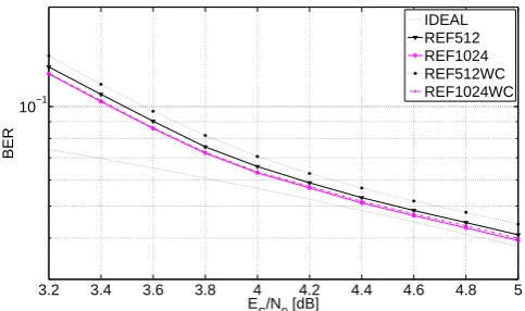
Fig. 2. Impact of different FFT length at low SNR.
The algorithm outlined in Eq. 17 to Eq. 19 needs as a prereq-uisite, that the residual frequency offset is quite small, i.e., the phase increase overL/2 elements of the sequencercmust
be less thanπ. If this condition is not fullfilled this algorithm produces considerable variations of the frequency estimation value.
4 Hardware architecture and implementation
4.1 Architecture
The base hardware architecture of the analyzed techniques is shown in Fig. 1. As mentioned we assume, that the process-ing steps of matched filterprocess-ing and timprocess-ing synchronization are properly carried out. As well an automatic gain control unit (AGC) is required to adapt the input sample bitwidth to the core input bit width without limiting dynamic range. The back-end must deal with theM-times phase ambiguity intro-duced by Eq. (9).
The building blocks of the core correspond directly to the base algorithm described in Sect. 2. The modulation removal component realizes Eq. (3) and provides the input for the FFT operation, which is given in Eq. (4). The spectral analy-sis component provides the estimates of frequency and phase offset according to Eq. 5 and Eq. (9). The RAM buffer is used to garantee constant throughput by hiding the FFT
la-9 9.5 10 10.5 11 11.5 12
10−4 10−3 10−2
ES/N0 [dB]
BER
IDEAL REF512 REF1024 REF512WC REF1024WC
Fig. 3. Impact of different FFT length at high SNR
tency. Thus a new sample sequencercan be processed while the already analyzed sequencerramis being corrected. The
phase and frequency correction component corresponds to Eq. (10). The shown techniques for improving the FFT accu-racy are realized by additional computations in the building blocks of Fig. 1. The SRR technique only impacts the mod-ulation removal component, the INT technique only impacts the spectral analysis component and the DD technique only impacts the correction component.
4.2 Implementation
We used synthetizable VHDL for implementing the architec-ture shown in Fig. 1 for the investigated techniques. For rapid development and to minimize debug effort we relied heavily on IP cores included in the XILINX Core Generator 9.1. We also used specific XILINX resources like the internal mul-tipliers (MULT) and block RAM (BRAM) available on the Spartan3-E FPGA. The modulation removal in Eq. 3 uses polar coordinates. The input samplesrhowever are given in Cartesian coordinates. The calculation of arg(r)and|r|can be done with the CORDIC algorithm (Volder, J., 1959) which is available as an IP core. We utilized the fully pipelined version of this CORDIC IP core to achieve a throughput of one sample per cycle. To realize the technique of sample rate reduction (see Equation 11) additionallyDsamples with modulation removal must be added. This is accomplished by some control logic, two adders and additional BRAM stor-age. The resulting sample sequencer˜ without modulation has to be transformed back to Cartesian coordinates for the FFT calculation (see Eq. 4) for all techniques. This is accom-plished with a sine-/cosine-look-up-table (SCL) also avail-able as an IP core and internal multipliers to realize theej x
operation.
3.5 4 4.5 5 5.5 10−2
10−1
ES/N0 [dB]
BER
IDEAL REF−512 DD−512 INT−512
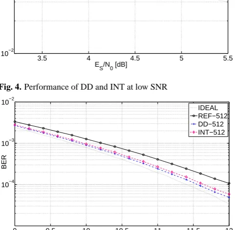
Fig. 4. Performance of DD and INT at low SNR
9 9.5 10 10.5 11 11.5 12
10−4 10−3 10−2
E
S/N0 [dB]
BER
IDEAL REF−512 DD−512 INT−512
Fig. 5. Performance of DD and INT at high SNR
desired throughput was one sample per cycle, the resulting core is fully pipelined and covers most of the area.
The windowing feature proposed in Equation 8 for eval-uatingkf w is realized in the spectral analysis block, using
a limited maximum absolute value search on the determined FFT bins. This can be implemented in a very efficient way by using only counters and comparators. After determining the frequency binkf w, the spectral analysis block estimates the
phase offset according to Eq.9. Again, the argument func-tion needed for this equafunc-tion is realized with a CORDIC IP core. Because only one argument calculation per phase esti-mation has to be performed, we can use a rather small serial CORDIC core without the ability to calculate|r|. The im-plementation of the INT technique requires some additional computations between search of the binkf and the argument
calculation for phase estimation. Additionally the right and left neighbour bin ofkf w must be selected and stored. The
realization of Eq. (14) requires a division, which is also avail-able as an XILINX IP core. Furthermore some adders and control logic is required to implement Eq. (15).
In the frequency and phase correction component rotation of the samples as described in Eq. (10) is accomplished with complex number multiplications and a second SCL. The de-cision directed technique requires additional hardware in this
3 3.5 4 4.5 5 5.5
10−2 10−1
E
S/N0 [dB]
BER
IDEAL REF1024 SRR−512 f1 SRR−512 f2
Fig. 6. Performance of SRR
component before the mentioned final correction can be per-formed. Calculation of the estimatess˜, the data aided mod-ulation removal according to Eq. (16) and the correlation ac-cording to Eq. (17) can be carried out in a pipelined manner. This requires addditional control logic, adders and internal multipliers. Again theargfunction and the divider are real-ized by a XILINX IP cores.
5 Results
5.1 Communications performance
In this section we present communications performance sim-ulations based on a bit true C model. All graphs are obtained using an addiditive white Gaussian noise (AWGN) channel model. A reference graphidealis provided to allow compar-ison of the simulation results to a perfect carrier synchroniza-tion reflecting the performance limits of the AWGN channel. Figure 2 and Fig. 3 show the bit error rate (BER) graphs for a burst with 300 QPSK modulated samples obtained by the base algorithm with a 512 point FFT and a 1024 point FFT, respectively. Two graphs result from a uniformly distributed frequency offset in the range[0.01· · ·0.02]. The other two graphs with the suffix identifier WC demonstrate the BER for a worst case szenario with frequency offset equal to a fre-quency exactly between two FFT bins. In high SNR region the 512 point FFT features a degradation up to 0.4 dB; in low SNR region a degradation of 0.1 dB can be observed. These simulations demonstrate the necessity to improve the results of the 512 point FFT.
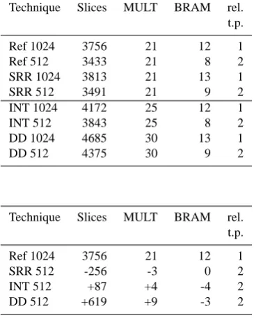
Table 1. Implementation resources of the analyzed techniques.
Technique Slices MULT BRAM rel. t.p.
Ref 1024 3756 21 12 1
Ref 512 3433 21 8 2
SRR 1024 3813 21 13 1
SRR 512 3491 21 9 2
INT 1024 4172 25 12 1
INT 512 3843 25 8 2
DD 1024 4685 30 13 1
DD 512 4375 30 9 2
Technique Slices MULT BRAM rel. t.p.
Ref 1024 3756 21 12 1
SRR 512 -256 -3 0 2
INT 512 +87 +4 -4 2
DD 512 +619 +9 -3 2
Table 2. Resource comparison
SNR regions the decision directed technique shows a very slight better performance than the interpolation technique.
For performance evaluation of the SRR technique the lower maximum frequency offset correction capability of this technique must be regarded. Hence we applied a window to the FFT results of the reference technique according to Eq. 8. Fig. 6 shows the performance of the SRR technique withD=2 for frequency offsets of 0.01 and 0.03. A severe degradation for the higher frequency offset can be observed. This behavior results from the fact that succesional modula-tion removed sample posses a higher phase difference, such that the average operation of Eq. (11) reduces the energy of the resulting sample sequencerˆs.
5.2 Implementation results
Target device was a low cost XILINX Spartan3-E FPGA de-vice. Synthesis as well as place and route was carried out with Xilinx ISE 9.1 software tools. Table 1 shows the XIL-INX resources for the different techniques using a 512 point FFT building block and a 1024 point FFT building block re-spectively. The achievable clock speed of 95 MHz is iden-tical for all techniques. The throughput of all investigated techniques depends linearely on the number of FFT points. Hence the throughput for the designs with 512 pint FFT is doubled in comparison to the 1024 point FFT based designs. In Table 1 the Xilinx resources of the reference technique with 1024 point FFT are compared with the resources for the other techniques based on a 512 point FFT.
6 Conclusions
The SRR technique exhibits the smallest implementation complexity of the analzed techniques. However the usabilty of this technique is limited by maximal occuring frequency offset and the performance requirements of the application. The other two techniques offer a comparable communica-tions performance and implementation complexity as the ref-erence technique. However both techniques offer a doubling of the achievable througput and thus provide clearly better efficiency. The DD technique requires more implementation ressources than the INT technique and provides only a neg-ligible better communications performance. With the three demonstrated techniques the design space for FFT based car-rier synchronization is enlarged, that a fitting of the imple-mentation to the throughput requirements and commucation performance requirements can be obtained.
References
Alles, M., Lehnigk-Emden, T., Wasenm¨uller, U., and Wehn, N.: Im-plementation Issues of Turbo Synchronization with Duo-Binary Turbo Decoding, Invited paper, 18th Annual IEEE International Symposium on Personal, Indoor and Mobile Radio Communica-tions (PIMRC), September, Athens, Greece, 2007.
Brack, T., Wasenm¨uller, U., Schmidt, D.,and Wehn, N.: De-sign Space Exploration for Frequency Synchronisation of BPSK/QPSK Bursts, Kleinheubacher Berichte, September 2004. Brack, T., Wasenm¨uller, U., and Wehn, N.: A configurable IP Core for Combined Blind Frequency and Phase Synchronization of MPSK Bursts, Proc. 2005 IST Mobile and Wireless Communi-cation Summit, 2005.
Mengali, U. and D’Andrea, A.: Synchronization Techniques for Digital Receivers, Plenum Publishing Corporation, 1997, New York, ISBN 0-306-45725-3, 1997.
Meyr, H., Moeneclaey, M., and Fechtel, S.: Digital Communication Receivers, John Wiley & Sons, Inc., New York, ISBN 0-471-50275-8, 1997.
Volder, J.: The CORDIC Trigonometric Computing Technique, IRE Transactions on Electronic Computing, 1959, September, 8, 330–334, 1959.