www.adv-radio-sci.net/12/187/2014/ doi:10.5194/ars-12-187-2014
© Author(s) 2014. CC Attribution 3.0 License.
Improved fault tolerance of Turbo decoding based on optimized
index assignments
J. Geldmacher and J. Götze
TU Dortmund University, Information Processing Lab, Otto-Hahn-Str. 4, 44227 Dortmund, Germany Correspondence to: J. Geldmacher ([email protected])
Received: 21 January 2014 – Accepted: 2 September 2014 – Published: 10 November 2014
Abstract. This paper investigates the impact of an error-prone buffer memory on a channel decoder as employed in modern digital communication systems. On one hand this work is motivated by the fact that energy efficient decoder implementations may not only be achieved by optimizations on algorithmic level, but also by chip-level modifications. One of such modifications is so called aggressive voltage scaling of buffer memories, which, while achieving reduced power consumption, also injects errors into the likelihood values used during the decoding process. On the other hand, it has been recognized that the ongoing increase of integra-tion density with smaller structures makes integrated circuits more sensitive to process variations during manufacturing, and to voltage and temperature variations. This may lead to a paradigm shift from 100 %-reliable operation to fault tol-erant signal processing. Both reasons are the motivation to discuss the required co-design of algorithms and underlying circuits. For an error-prone receive buffer of a Turbo decoder the influence of quantizer design and index assignment on the error resilience of the decoding algorithm is discussed. It is shown that a suitable design of both enables a compensation of hardware induced bits errors with rates up to 1 % without increasing the computational complexity of the decoder.
1 Introduction
Two impact factors for the power consumption of a signal processing circuit can be identified: Power consumption of the logic (roughly related to the algorithmic complexity) and power consumption of the involved buffer memory. The lat-ter is related to the number of read-write operations and their reduction has become a key factor when designing energy efficient algorithms. Especially in state-of-the-art baseband
signal processing, where large blocks are often processed in an iterative fashion, memory access is a major power con-suming part. At the same time, system on chips (SoCs) are dominated in terms of area by the embedded memory.
Given that embedded memories are already highly struc-tured and highly optimized devices, there is less potential for energy optimization if hard quality constraints are rein-forced. However, if relaxing quality requirements in a con-trolled fashion, significant energy reduction can be achieved: In aggressive voltage scaling (AVS) (Hegde and Shanbhag, 2001; Djahromi et al., 2007; Makhzan et al., 2007), the sup-ply voltage of an embedded circuit is deliberately reduced below the required threshold. This leads to substantial reduc-tion of power consumpreduc-tion, but also to unreliable operareduc-tion of the circuit. But while the latter would introduce process-ing errors and serious performance degradation of the whole system if circuit logic was affected, it can be tolerated up to a certain level for some applications in case of embedded memories. This is for example true for baseband signal pro-cessing systems, like channel decoders, which are actually designed to deal with error-prone data and can thus be ex-tended to deal with deliberately introduced errors as well. As an example, Hussien et al. (2010) propose an error-resilient Viterbi decoder architecture, where power savings of 15 % to 20 % are achieved while the bit error rate (BER) performance degradation is insignificant.
opment of fault tolerant (error resilient) systems cannot be dealt with in a single perspective, but rather that a cross-layer view is required: A co-design of embedded circuits and signal-processing algorithms will be necessary to efficiently exploit potentials of approaches like AVS and to obtain rela-tively reliable systems based on unreliable underlying com-ponents. This approach constitutes a “paradigm shift from 100 %-reliable operation to fault tolerant signal processing” (Novak et al., 2010).
In context of baseband signal processing and channel de-coding, a few authors have addressed a co-design with er-roneous circuits under different conditions: The inherent fault-tolerance of communication systems is exploited by Djahromi et al. (2007), where the authors identify a du-ality between communication channel errors and hardware induced errors. Based on this observation they propose to adapt the supply voltage depending on the current working condition of the system; by reducing the supply voltage in case of good reception conditions they achieve power sav-ings of around 45 % in a WCDMA receiver The resilience of Viterbi and MaxLog decoding against timing errors and memory errors introduced by voltage overscaling is treated in Liu et al. (2009), where power savings of about 44 % and 38 % are reported for Viterbi and MaxLog decoders, respec-tively. The authors of Abdallah and Shanbhag (2009) also deal with Viterbi decoding and the influence of timing errors due to process variations and voltage scaling. They investi-gate several low level methods to improve error resilience and achieve significant power savings of up to 71 % with a small tolerated loss of coding gain. A more abstract treatment of error-resilient Viterbi decoding using an erroneous receive buffer is provided by Hussien et al. (2010), where the authors employ a statistical model of the combined communication channel and hardware noise to derive a suitable branch met-ric. They also show that the branch metric computation can be kept simple in case of Two’s complement representation of the quantization symbols and report a reduction of power consumption in the order of 15 % to 20 % with small loss of coding gain. The authors extend their approach in Hussien et al. (2011) to LDPC and Turbo decoders considering the receive (ARQ) buffer; in Khairy et al. (2012) they also study its application to MIMO detection. For an LDPC decoder Alles et al. (2007); May et al. (2008) propose a reliability-aware design, which improves the protection against timing and signal errors by using simple error correction and detec-tion techniques. Low and high level approaches to improve error-resilience of a Turbo decoder are investigated by Brehm et al. (2012). On algorithm level, the authors propose an in-crease of iteration number to facilitate resilience against tim-ing errors and soft errors. The same authors also study the re-silience of a MIMO-BICM system with iterative receiver and hardware errors that manifest as transient bit errors in various
Considering the problem of improving resilience of chan-nel decoding algorithms against memory defects under more general, algorithmic perspective, it is interesting, that only the works by Kurdahi, Eltawil, et al. (Hussien et al., 2010, 2011) consider modification and adaption of the decoding algorithm itself. Furthermore, the strong relation of the given problem to source channel coding and robust quantizer de-sign has only been pointed out in Novak et al. (2010); Roth et al. (2012), while its significance is long known in those fields. Novak et al. (2010) consider a MIMO BICM system with unreliable storage of the received log-likelihood ratio (LLR) values. The authors investigate the influence of (re-dundant) index assignments and simple forward error cor-rection codes for the indices in terms of achievable rate and conclude that in case of non-redundant indices the selection of a robust index assignment is crucial, while in case of re-dundant labels the decision between simple FEC coding and customized index assignment depends on the SNR operation state of the underlying system. The authors address the first point more extensively in Roth et al. (2012) and stress the importance of application specific index assignments. They discuss the cases of repetition coding and convolutional cod-ing and derive optimized index assignments through exhaus-tive search. For a Turbo decoder with unreliable LLR buffer, an index assignment optimization strategy based on the EXIT characteristics of the decoder is described in Geldmacher and Götze (2013). The authors show that the resulting assign-ments provide improved error-resilience without increasing decoding complexity.
In this article, the influence of optimized index assignment and quantizer design on a Turbo decoder with unreliable re-ceive buffer memory is studied. This scenario of communica-tion channel with quantized output and successive unreliable buffer memory is modeled as a cascade of two discrete mem-oryless channels (DMCs); the index assignment is regarded as a way to connect both DMCs. It is shown that joint opti-mization of index assignment and quantizer can significantly improve error-resilience of the decoder, without increasing its computational complexity.
2 Problem description
2.1 System model
The model shown in Fig. 1 is employed to discuss the prob-lem of an unreliable buffer memory. A source generates Gaussian distributed valuesr˜from the original equiprobable and independent symbolsx∈ {±1},
˜
r=µrx+n, where n∼N(0, σr2). (1)
Figure 1. Model of a Gaussian source with successive quantizer and buffer memory.
The source abstractly models for example an AWGN com-munication channel, with a certain gainµr and a noise vari-anceσr2, or it may be a so called a priori channel representing a SISO component in an iterative processing system, e.g. a MAP decoder. Given the continuous, Gaussian distributed valuesr, the˜ N-Bit quantizer assigns discrete reconstruction values r from a finite setQ of size|Q| =2N in a suitable fashion. In the following the quantizer is designed using uni-form and fixed reconstruction values from a set
Q= {−2d−1+k2−f :0≤k <2N}, (2) wheredandf are decimal and fractional bits andd+f=N. This approach is simple and might not include the opti-mum quantizer design with respect to the mean-squared-error (MSE) or the average mutual information (MI), but it seems practically relevant and enables us to discuss effects of the memory channel disturbance. To account for changing channel conditions (µr andσr2), the scaling factorγ can be used as an adaptive gain control and scale the quantizer input to the quantization range. In some use cases, for example if the source models a constituent decoder in a Turbo decoding framework, the scalerγ might, however, be fixed for practi-cal reasons. Given the setQ, the probability mass function (PMF) P (r|x)of the quantized values r conditioned on x can be found by integrating over the individual quantization intervals.
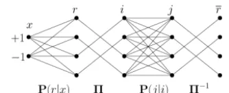
The quantization scheme coincides with the Two’s com-plement representation, if the assignment from quantization indexkto the indexi, whose binary representation is stored in the buffer, is selected as i=k⊕2d−1 with ⊕ denoting the XOR operation and i∈ {0, . . . ,2N−1}. In general, how-ever, any mapping from quantization values to indices may be used. We refer to this bijective mapping as the index as-signment and denote a specific one-to-one relation between kandiby5,i=5(k), and its reverse as5−1. The binary representation of the integeriis written to the buffer mem-ory. As in Novak et al. (2010); Khajeh et al. (2010), spatially independent and uniformly distributed errors on the memory cells are assumed, such that the memory channel can be seen as a binary symmetric channel (BSC) with input and output the binary representations of i andj, respectively. It is re-ferred to as the memory channel in the following. Given the bit error probabilitype, the probability of reading an indexj under the condition thatihas been written to the memory is given as
P (j|i)=pdH(i,j )
e (1−pe)N−dH(i,j ), (3)
Figure 2. Abstract representation of the AWGN channel with suc-cessive quantizer and unreliable buffer memory as DMC cascade.
wheredH(i, j ) is the Hamming distance between i andj.
Given the fact that the index assignment is a bijective map-ping, then for the PMF of the reconstructed quantization symbolsr∈Qconditioned onxit holds that
P (r|x)=P (5−1(j )|x). (4)
2.2 Characteristics of memory channel
The transmission matrix (Cover and Thomas, 1991, p. 189) of the AWGN channel with quantized outputs and binary in-put is a(2×2N)-matrix and it can be written as
P(r|x)=
P (q0| −1) . . . P (q2N−1| −1)
P (q0| +1) . . . P (q2N−1| +1)
, (5)
withqk∈Qthe reconstruction values of the quantizer. The (2N×2N)-matrix of the memory channel is given as
P(j|i)=
P (0|0) . . . P (2N−1|0) ..
. . .. ...
P (0|2N−1) . . . P (2N−1|2N−1)
. (6)
To obtain the transmission matrix P(r|x)of the concatena-tion of both channels, the index assignment has also to be considered. As it is a mapping of quantizer output to mem-ory channel input, it may be represented by a matrix5, that permutes the columns of P(r|x)in the required order. The re-verse permutation has to be applied to the columns of P(j|i) using the transpose of5. Then we have the transmission ma-trix as
P(r|x)=P(r|x)5P(j|i)5T, (7) where5is for example given as
5=
I2N−1
I2N−1
for Two’s complement, (8) or as5=I2N for natural binary coding (NBC).
P (r|r, x)=P (r|r). (9) Now letR,RandXbe the random variables representingr, r andx, respectively. Then Eq. (9) is justified by the obser-vation that onceRis known,Rcannot reveal any additional information aboutX, because there is no connection between XandRother than the cascade of communication and mem-ory channel. This means that the MI ofXandRconditioned onRvanishes,
I (X;R|R)=0, (10)
and thusX, R, R form a Markov chainX→R→R. Now some interpretations can be derived: First the chain rule of mutual information (Cover and Thomas, 1991, p. 22) may be applied as
I (X;R, R) = I (X;R)+I (X;R|R)
= I (X;R)+I (X;R|R). (11) Then using Eq. (10) yields
I (X;R)=I (X;R)−I (X;R|R). (12) Equation (12) shows that the MI of R and X can only be smaller than or equal to the MI of R and X, given non-negativity of the MI. Equality holds ifpe=0, in which case R=Rand consequentlyI (X;R|R)=0:
I (X;R) < I (X;R) for pe>0 and
I (X;R)=I (X;R) for pe=0. (13) Thus the memory channel output will be degraded ifpe> 0, while it matches the output of the communication channel for pe=0. The term I (X;R|R)from Eq. (12), which de-notes the MI loss at memory channel output, can be further rewritten,
I (X;R|R) = H (R|R)−H (R|R, X)
= H (R|R)−H (R)+H (R)−H (R|R, X) = −I (R;R)+H (R)−H (R|R, X), (14) and it can be seen that the degradation of MI depends on
– the error probabilitype of the memory channel, repre-sented by the MII (R;R)of its in- and output,
– on the design of the quantizer, represented by the en-tropyH (R)of its output, and
– the interaction of all components, including the index assignment, represented byH (R|R, X).
should be carried out subject to the quantizer (represented by the scalerγ) and the index assignment5. This approach is investigated in the following section for a Turbo decoding scenario.
3 Turbo decoder with unreliable receive buffer
3.1 System model
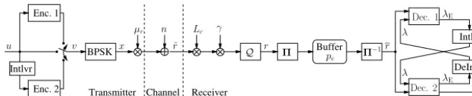
In the following, the transmission of BPSK-modulated Turbo coded data with rateRc over a communications channel is modeled as shown in Fig. 3: Binary information symbolsu are encoded using two parallel concatenated recursive sys-tematic convolutional encoders, such that the coded symbols vconsist of a systematic part and two parity parts from first and second encoder. BPSK modulation ofv results in the equally probable modulation symbolsx=2v−1. A gain fac-torµr may be applied, such that the symbolsµrx are trans-mitted eventually.
The communication channel is modeled as an AWGN channel, so that the received valuesr˜can be written as ˜
r=µrx+n, wheren∼N(0, σr2), (15) whereσr2denotes the noise power of the channel. The chan-nel is characterized by its signal-to-noise ratio:
Eb/N0|dB=10 log10
µ2r 2Rcσr2
. (16)
Before quantization, the received symbols are weighted with the channel reliability Lc and scaled to the quantizers dy-namic range usingγ. It is assumed that perfect channel state information is available to the receiver, such that the quan-tizer input will be the scaled LLR
γ·logp(r˜|v=1)
p(r˜|v=0) = γ·log
exp −(r˜−µr)2/2σr2
exp −(r˜+µr)2/2σr2
= γ2µr
σr2 r˜=γ Lcr.˜ (17) The quantizer assigns reconstruction valuesrfrom the set of Two’s complement values as given in Eq. (2) withf =0 and N=d. The scaling factorγ still allows to achieve a set of reconstruction values including any combination ofd andf withN=d+f.
After quantization the index assignment5assigns indices ito the quantized values and the corresponding binary rep-resentation is stored in the receive buffer. The buffer is char-acterized by its error probabilitype, such that the restored indicesj may differ from the written indicesi. Based on the corresponding restored symbolsr the Turbo decoder com-putes an estimateuˆ of the original information by iterating
Buffer
Intlvr
Receiver BPSK
Transmitter
Intlvr
DeIntlvr
Channel Enc. 2
Enc. 1
Q r r
˜
r
λE
λE
λ
λ
ˆ
u pe
x
Lc
µr n γ
v u
Π−1
Dec. 1
Dec. 2
Π
Fig. 3.System model for Turbo coded transmission with unreliable receive and LLR buffer.
interleaved/de-interleaved and become thea prioriLLRsλ
of the second/first decoder in the next stage.
340
A rate Rc= 1/3 Turbo code with generator G(D) =
h
1, D3+D+1 D3
+D2
+1
i
and length 215 random interleaver is
em-ployed in the following. Both encoders are terminated and the resulting tails are transmitted along with the systematic and parity parts. The transmission gain isµr= 1. In the
fol-345
lowing a conventional LogMAP based Turbo decoder is com-pared to a fault tolerant (FT) decoder. The number of itera-tions carried out by the decoder is fixed to 8. The FT decoder works like the conventional decoder, with the exception that its transition metric is based on the actual transition
proba-350
bilityP(r|x)of the cascade of communication and memory channel (Geldmacher and G¨otze, 2012). It employs a look-up table (LUT) of size2Nwhich holds the log domain represen-tation ofP(r|x). The values obtained by indexing this LUT using the indicesj replace the received values in the
transi-355
tion metric of a conventional MAP algorithm. The LUT is constructed once per received frame by estimating the statis-tics ofr, computingP(r|x)based on (7) and storing its log-arithm.
3.2 Optimized Index Assignment 360
Following (13), the unreliable receive buffer, represented by a BSC with error probabilitypewill cause a decrease of MI. The MI I(X;R) is clearly a function of P(r|x) which in turn depends for a fixed Eb/N0, pe and Q on the scaling parameterγand the index assignmentΠ. Thus the MI for a
365
given pair(γ,Π)is denoted byI(γ,Π)(X;R). Consequently
it is reasonable that for a givenEb/N0,peandQ, there is a combination(Π∗, γ∗)that maximizesI
(γ,Π)(X;R):
(Π∗, γ∗) = arg max
Π,γ I(γ,Π)(X;R) (18)
Problem (18) can be solved by first finding optimizedΠ∗(γ)
370
for reasonable values ofγ:
Π∗(γ) = arg max
Π I(γ,Π)(X;R), (19)
Thenγ∗can be selected as
γ∗= arg max
γ I(γ,Π∗(γ))(X;R)andΠ
∗= Π∗(γ∗), (20)
Solving (19) for an optimized index assignmentΠ∗(γ)is a combinatorial optimization problem. Given the fact, that the number of possible index assignments for an N-Bit quan-tization is given by(2N)!, from which(2N−1)!/N! yield distinct results (Azami et al., 1996), one has therefor to
re-380
sort to heuristic optimization algorithms forN >3. A meta-heuristic which had already turned out efficient for other combinatorial problems is simulated annealing (e.g. Reeves (1993); Farvardin (1990)); it is employed in this work to solve (19).
385
The result of this optimization is illustrated in Fig. 4 (left), where the MI I(X;R)is shown as a function of the scaler
γ for optimized index assignment Π∗ and NBC Π
NBC. In
general it can be noticed, that the memory channel causes a reduction of achievable MII(X;R)compared to the
ref-390
erence I(X;R). Also, it can be observed that the MI de-pends onγ and that the optimalγ is different in all consid-ered cases. This implies that even if the index assignment is not modified, the scaling factor should be adapted to the memory channel, because otherwise, a performance
reduc-395
tion may take place: For example, takingN = 4, the optimal scaler forpe= 0(I(X;R), “Ref”) is about 2, which leads to
I(X;R) = 0.370(Π∗ andΠ
NBC), while actually greater MI
would be possible by selectingγ= 3. The figure also shows that a larger quantization width than actually required to
ac-400
curately representR˜allows for a larger gain due to the opti-mized index assignment: While forN= 4there is only little improvement ofΠ∗overΠ
NBC, a larger quantization width of N = 6enables a significantly increasedI(X;R). The reason for this can be found in the larger redundancy available inR,
405
which provides more degrees of freedom to the index assign-ment optimization, and thus yields a more effective protec-tion against errors induced by the memory channel.
3.3 EXIT Chart
The influence of optimized index assignment and
quantiza-410
tion widthNon the decoding behaviour is first studied using EXIT charts. Consider Fig. 4 (right), where the performance of conventional Turbo decoder (“MAP”) and FT decoder (“FTMAP”) using NBC index assignment (ΠNBC) are
com-pared for two different quantization widthsN = 4andN = 6
415
and pe= 0.01. As a reference the chart for a decoder with
pe= 0and identical quantization settings is shown (“Ref.”) Figure 3. System model for Turbo coded transmission with unreliable receive and LLR buffer.
between the two constituent decoders. Both constituent de-coders implement the BCJR algorithm (Bahl et al., 1974) in log-domain on the trellis of the encoder to produce extrin-sic LLRs λE of the information symbols: More concisely,
the first decoder employs the systematic part and the first parity part of r, while the second decoder uses the inter-leaved systematic part and the second parity part of r. The extrinsic LLRsλEgenerated by the first/second decoder are
interleaved/de-interleaved and become the a priori LLRs λ of the second/first decoder in the next stage.
A rate Rc=1/3 Turbo code with generator G(D)=
h
1, D3+D+1 D3+D2+1 i
and length 215 random interleaver is em-ployed in the following. Both encoders are terminated and the resulting tails are transmitted along with the systematic and parity parts. The transmission gain isµr =1. In the fol-lowing a conventional LogMAP based Turbo decoder is com-pared to a fault tolerant (FT) decoder. The number of itera-tions carried out by the decoder is fixed to 8. The FT decoder works like the conventional decoder, with the exception that its transition metric is based on the actual transition proba-bilityP (r|x)of the cascade of communication and memory channel (Geldmacher and Götze, 2012). It employs a look-up table (LUT) of size 2Nwhich holds the log domain represen-tation ofP (r|x). The values obtained by indexing this LUT using the indicesj replace the received values in the tran-sition metric of a conventional MAP algorithm. The LUT is constructed once per received frame by estimating the statis-tics ofr, computingP (r|x)based on Eq. (7) and storing its logarithm.
3.2 Optimized index assignment
Following Eq. (13), the unreliable receive buffer, represented by a BSC with error probabilitypewill cause a decrease of MI. The MI I (X;R)is clearly a function ofP (r|x)which in turn depends for a fixedEb/N0,peandQon the scaling parameterγ and the index assignment5. Thus the MI for a given pair(γ , 5)is denoted byI(γ ,5)(X;R). Consequently it is reasonable that for a givenEb/N0,peandQ, there is a combination(5∗, γ∗)that maximizesI(γ ,5)(X;R):
5∗, γ∗=
arg max
5,γ I(γ ,5)(X
;R) (18)
Problem Eq. (18) can be solved by first finding optimized 5∗(γ )for reasonable values ofγ:
5∗(γ )=arg max
5 I(γ ,5)(X
;R), (19)
Thenγ∗can be selected as
γ∗=arg max γ I(γ ,5
∗(γ ))(X;R)and5∗=5∗(γ∗), (20)
which yields the optimal combination of(5∗, γ∗).
Solving Eq. (19) for an optimized index assignment5∗(γ ) is a combinatorial optimization problem. Given the fact, that the number of possible index assignments for anN-Bit quan-tization is given by (2N)!, from which(2N−1)!/N! yield distinct results (Azami et al., 1996), one has therefor to re-sort to heuristic optimization algorithms forN >3. A meta-heuristic which had already turned out efficient for other combinatorial problems is simulated annealing (e.g. Reeves, 1993; Farvardin, 1990); it is employed in this work to solve Eq. (19).
The result of this optimization is illustrated in Fig. 4 (left), where the MII (X;R)is shown as a function of the scaler γ for optimized index assignment 5∗ and NBC 5NBC. In
general it can be noticed, that the memory channel causes a reduction of achievable MII (X;R)compared to the ref-erence I (X;R). Also, it can be observed that the MI de-pends onγ and that the optimal γ is different in all con-sidered cases. This implies that even if the index assignment is not modified, the scaling factor should be adapted to the memory channel, because otherwise, a performance reduc-tion may take place: For example, takingN=4, the optimal scaler forpe=0 (I (X;R), “Ref”) is about 2, which leads to I (X;R)=0.370 (5∗and5NBC), while actually greater MI
would be possible by selectingγ=3. The figure also shows that a larger quantization width than actually required to ac-curately representR˜ allows for a larger gain due to the opti-mized index assignment: While forN=4 there is only little improvement of5∗over5NBC, a larger quantization width
1926 J. Geldmacher and J. Götze: Improved fault tolerance of Turbo decodingJ. Geldmacher et al.: Improved Fault Tolerance of Turbo Decoding
1 3 5 7 9 11 13 15
0.34 0.35 0.36 0.37 0.38 0.39 0.4
Scaling factorγ
M
I
Ref (I(X;R),N= 4)
Π∗(I(X;R),N= 4) ΠNBC (I(X;R),N= 4) Ref (I(X;R),N= 6)
Π∗(I(X;R),N= 6) ΠNBC (I(X;R),N= 6)
0.001 0.001 0.001 0.001 0.005 0.005 0.005 0.005 0.01 0.01 0.01 0.02 0.02 0.02 0.04 0.04 0.04 0.06 0.06 0.08 0.08 0.1 0.1 D ec o d er 1 I ( X ; ΛE ) -D ec o d er 2 I ( X ; Λ )
Decoder 1I(X;Λ) - Decoder 2I(X;ΛE)
0 0.1 0.2 0.3 0.4 0.5 0.6 0.7 0.8 0.9 1 0 0.1 0.2 0.3 0.4 0.5 0.6 0.7 0.8 0.9 1 Ref. FTMAP MAP
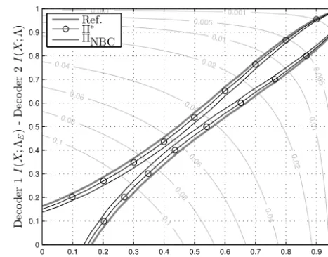
Fig. 4.Left: Mutual information after receive buffer for NBC and optimized index assignment forN= 4and N= 6(Eb/N0= 0.5dB, pe= 0.01, Rc= 1/3). Right: EXIT chart of conventional and FT Turbo decoder with unreliable receive buffer forN= 4(pe= 0.01, Eb/N0= 0.25dB, NBC, BER estimate as contour lines)
received values experience additional distortion due to the
420
memory channel, then the tunnel becomes much smaller and decoding performance will be deteriorated. In Fig. 4 (right), where a quantization width ofN= 4 is used, this impact appears like a small SNR degradation on the communica-tion channel and manifests as a reduccommunica-tion of the EXIT
tun-425
nel. It can also be observed, that in this case, there is only very little difference between the conventional decoder and the fault tolerant decoder, and only very close observation reveals the slight improvement due to latter. Convergence to BERs smaller than about0.08cannot be expected for both
430
decoders.
However, increasing the quantization width toN= 6Bit, as shown Fig. 5, leads to a significant difference between both decoders: The conventional decoder exhibits a
substan-0.001 0.001 0.001 0.001 0.005 0.005 0.005 0.005 0.01 0.01 0.01 0.02 0.02 0.02 0.04 0.04 0.04 0.06 0.06 0.08 0.08 0.1 0.1 D ec o d er 1 I ( X ; ΛE ) -D ec o d er 2 I ( X ; Λ )
Decoder 1I(X;Λ) - Decoder 2I(X;ΛE)
0 0.1 0.2 0.3 0.4 0.5 0.6 0.7 0.8 0.9 1 0 0.1 0.2 0.3 0.4 0.5 0.6 0.7 0.8 0.9 1 Ref. FTMAP MAP
Fig. 5.EXIT chart of conventional and FT Turbo decoder with un-reliable receive buffer forN= 6(pe= 0.01, Eb/N0= 0.25dB,
NBC, BER estimate as contour lines).
tial performance degradation, which is indicated by a very
435
early crossing of the EXIT curves. In fact even for very good
a prioriinformation (I(X; Λ)→1), the decoder is not capa-ble of producing improved extrinsic information, such that decoding performance is expected to be strongly degraded. The FT decoder on the other hand shows an improved EXIT
440
chart compared to theN= 4case: While the tunnel is still considerably smaller than for the reference, the curves do not intersect and given a sufficient number of iterations the de-coder may be able to achieve reference BER performance. Thus it can be concluded that while an increased
quantiza-445
tion width amplifies the impact of the memory channel and degrades performance of a conventional decoder, it also en-ables improved error-resilience due to increased redundancy
0.001 0.001 0.001 0.001 0.005 0.005 0.005 0.005 0.01 0.01 0.01 0.02 0.02 0.02 0.04 0.04 0.04 0.06 0.06 0.08 0.08 0.1 0.1 D ec o d er 1 I ( X ; ΛE ) -D ec o d er 2 I ( X ; Λ )
Decoder 1I(X;Λ) - Decoder 2I(X;ΛE)
0 0.1 0.2 0.3 0.4 0.5 0.6 0.7 0.8 0.9 1 0 0.1 0.2 0.3 0.4 0.5 0.6 0.7 0.8 0.9 1 Ref. Π∗ ΠNBC
Fig. 6.EXIT chart for NBC and optimized index assignment for
N= 4(pe= 0.01,Eb/N0= 0.25dB, FT decoder).
Figure 4. Left: Mutual information after receive buffer for NBC and optimized index assignment forN=4 andN=6 (Eb/N0=0.5 dB,
pe=0.01,Rc=1/3). Right: EXIT chart of conventional and FT Turbo decoder with unreliable receive buffer forN=4 (pe=0.01, Eb/N0=0.25 dB, NBC, BER estimate as contour lines).
1 3 5 7 9 11 13 15
0.34 0.35 0.36 0.37 0.38 0.39
Scaling factorγ
M
I
Ref (I(X;R),N= 4)
Π∗(I(X;R),N= 4)
ΠNBC (I(X;R),N= 4) Ref (I(X;R),N= 6)
Π∗(I(X;R),N= 6)
ΠNBC (I(X;R),N= 6)
0.001 0.001 0.005 0.005 0.01 0.02 0.02 0.04 0.04 0.04 0.06 0.06 0.08 0.08 0.1 0.1 D ec o d er 1 I ( X ; ΛE ) -D ec o d er 2 I ( X
Decoder 1I(X;Λ) - Decoder 2I(X;ΛE)
0 0.1 0.2 0.3 0.4 0.5 0.6 0.7 0.8 0.9 1
0 0.1 0.2 0.3 0.4 0.5 0.6 0.7 0.8
Fig. 4.Left: Mutual information after receive buffer for NBC and optimized index assignment for N= 4andN = 6(Eb/N0= 0.5dB,
pe= 0.01,Rc= 1/3). Right: EXIT chart of conventional and FT Turbo decoder with unreliable receive buffer forN= 4 (pe= 0.01, Eb/N0= 0.25dB, NBC, BER estimate as contour lines)
received values experience additional distortion due to the
420
memory channel, then the tunnel becomes much smaller and
decoding performance will be deteriorated. In Fig. 4 (
right
),
where a quantization width of
N
= 4
is used, this impact
appears like a small SNR degradation on the
communica-tion channel and manifests as a reduccommunica-tion of the EXIT
tun-425
nel. It can also be observed, that in this case, there is only
very little difference between the conventional decoder and
the fault tolerant decoder, and only very close observation
reveals the slight improvement due to latter. Convergence to
BERs smaller than about
0
.
08
cannot be expected for both
430
decoders.
However, increasing the quantization width to
N
= 6
Bit,
as shown Fig. 5, leads to a significant difference between
both decoders: The conventional decoder exhibits a
substan-0.001 0.001 0.001 0.001 0.005 0.005 0.005 0.005 0.01 0.01 0.01 0.02 0.02 0.02 0.04 0.04 0.04 0.06 0.06 0.08 0.08 0.1 0.1 D ec o d er 1 I ( X ; ΛE ) -D ec o d er 2 I ( X ; Λ )
Decoder 1I(X;Λ) - Decoder 2I(X;ΛE)
0 0.1 0.2 0.3 0.4 0.5 0.6 0.7 0.8 0.9 1
0 0.1 0.2 0.3 0.4 0.5 0.6 0.7 0.8 0.9 1 Ref. FTMAP MAP
Fig. 5.EXIT chart of conventional and FT Turbo decoder with un-reliable receive buffer for N= 6 (pe= 0.01, Eb/N0= 0.25dB,
NBC, BER estimate as contour lines).
tial performance degradation, which is indicated by a very
435
early crossing of the EXIT curves. In fact even for very good
a priori
information (
I
(
X
; Λ)
→
1
), the decoder is not
capa-ble of producing improved extrinsic information, such that
decoding performance is expected to be strongly degraded.
The FT decoder on the other hand shows an improved EXIT
440
chart compared to the
N
= 4
case: While the tunnel is still
considerably smaller than for the reference, the curves do not
intersect and given a sufficient number of iterations the
de-coder may be able to achieve reference BER performance.
Thus it can be concluded that while an increased
quantiza-445
tion width amplifies the impact of the memory channel and
degrades performance of a conventional decoder, it also
en-ables improved error-resilience due to increased redundancy
0.001 0.001 0.001 0.001 0.005 0.005 0.005 0.005 0.01 0.01 0.01 0.02 0.02 0.02 0.04 0.04 0.04 0.06 0.06 0.08 0.08 0.1 0.1 D ec o d er 1 I ( X ; ΛE ) -D ec o d er 2 I ( X ; Λ )
Decoder 1I(X;Λ) - Decoder 2I(X;ΛE)
0 0.1 0.2 0.3 0.4 0.5 0.6 0.7 0.8 0.9 1
0 0.1 0.2 0.3 0.4 0.5 0.6 0.7 0.8 0.9 1 Ref. Π∗ ΠNBC
Fig. 6.EXIT chart for NBC and optimized index assignment for
N= 4(pe= 0.01,Eb/N0= 0.25dB, FT decoder).
Figure 5. EXIT chart of conventional and FT Turbo decoder with unreliable receive buffer forN=6 (pe=0.01,Eb/N0=0.25 dB,
NBC, BER estimate as contour lines).
3.3 EXIT chart
The influence of optimized index assignment and quantiza-tion widthNon the decoding behaviour is first studied using EXIT charts. Consider Fig. 4 (right), where the performance of conventional Turbo decoder (“MAP”) and FT decoder (“FTMAP”) using NBC index assignment (5NBC) are
com-pared for two different quantization widthsN=4 andN=6 andpe=0.01. As a reference the chart for a decoder with pe=0 and identical quantization settings is shown (“Ref.”) – given the width of the tunnel, it can be expected that the decoder will converge at thisEb/N0level. If, however, the
received values experience additional distortion due to the memory channel, then the tunnel becomes much smaller and
1 3 5 7 9 11 13 15
0.34 0.35 0.36 0.37 0.38
Scaling factorγ
M
I
Ref (I(X;R),N= 4)
Π∗(I(X;R),N= 4)
ΠNBC (I(X;R),N= 4) Ref (I(X;R),N= 6)
Π∗(I(X;R),N= 6)
ΠNBC (I(X;R),N= 6)
0.001 0.005 0.005 0.01 0.02 0.02 0.04 0.04 0.04 0.06 0.06 0.08 0.08 0.1 0.1 D ec o d er 1 I ( X ; ΛE ) -D ec o d er 2 I (
Decoder 1I(X;Λ) - Decoder 2I(X;ΛE)
0 0.1 0.2 0.3 0.4 0.5 0.6 0.7 0.8 0.9 1
0 0.1 0.2 0.3 0.4 0.5 0.6 0.7 0.8
Fig. 4.Left: Mutual information after receive buffer for NBC and optimized index assignment forN= 4and N= 6(Eb/N0= 0.5dB,
pe= 0.01, Rc= 1/3).Right: EXIT chart of conventional and FT Turbo decoder with unreliable receive buffer for N= 4(pe= 0.01, Eb/N0= 0.25dB, NBC, BER estimate as contour lines)
received values experience additional distortion due to the
420
memory channel, then the tunnel becomes much smaller and
decoding performance will be deteriorated. In Fig. 4 (
right
),
where a quantization width of
N
= 4
is used, this impact
appears like a small SNR degradation on the
communica-tion channel and manifests as a reduccommunica-tion of the EXIT
tun-425
nel. It can also be observed, that in this case, there is only
very little difference between the conventional decoder and
the fault tolerant decoder, and only very close observation
reveals the slight improvement due to latter. Convergence to
BERs smaller than about
0
.
08
cannot be expected for both
430
decoders.
However, increasing the quantization width to
N
= 6
Bit,
as shown Fig. 5, leads to a significant difference between
both decoders: The conventional decoder exhibits a
substan-0.001 0.001 0.001 0.001 0.005 0.005 0.005 0.005 0.01 0.01 0.01 0.02 0.02 0.02 0.04 0.04 0.04 0.06 0.06 0.08 0.08 0.1 0.1 D ec o d er 1 I ( X ; ΛE ) -D ec o d er 2 I ( X ; Λ )
Decoder 1I(X;Λ) - Decoder 2I(X;ΛE)
0 0.1 0.2 0.3 0.4 0.5 0.6 0.7 0.8 0.9 1
0 0.1 0.2 0.3 0.4 0.5 0.6 0.7 0.8 0.9 1 Ref. FTMAP MAP
Fig. 5.EXIT chart of conventional and FT Turbo decoder with un-reliable receive buffer for N= 6 (pe= 0.01, Eb/N0= 0.25dB,
NBC, BER estimate as contour lines).
tial performance degradation, which is indicated by a very
435
early crossing of the EXIT curves. In fact even for very good
a priori
information (
I
(
X
; Λ)
→
1
), the decoder is not
capa-ble of producing improved extrinsic information, such that
decoding performance is expected to be strongly degraded.
The FT decoder on the other hand shows an improved EXIT
440
chart compared to the
N
= 4
case: While the tunnel is still
considerably smaller than for the reference, the curves do not
intersect and given a sufficient number of iterations the
de-coder may be able to achieve reference BER performance.
Thus it can be concluded that while an increased
quantiza-445
tion width amplifies the impact of the memory channel and
degrades performance of a conventional decoder, it also
en-ables improved error-resilience due to increased redundancy
0.001 0.001 0.001 0.001 0.005 0.005 0.005 0.005 0.01 0.01 0.01 0.02 0.02 0.02 0.04 0.04 0.04 0.06 0.06 0.08 0.08 0.1 0.1 D ec o d er 1 I ( X ; ΛE ) -D ec o d er 2 I ( X ; Λ )
Decoder 1I(X;Λ) - Decoder 2I(X;ΛE)
0 0.1 0.2 0.3 0.4 0.5 0.6 0.7 0.8 0.9 1
0 0.1 0.2 0.3 0.4 0.5 0.6 0.7 0.8 0.9 1 Ref. Π∗ ΠNBC
Fig. 6. EXIT chart for NBC and optimized index assignment for
N= 4(pe= 0.01,Eb/N0= 0.25dB, FT decoder).
Figure 6. EXIT chart for NBC and optimized index assignment for N=4 (pe=0.01,Eb/N0=0.25 dB, FT decoder).
decoding performance will be deteriorated. In Fig. 4 (right), where a quantization width ofN=4 is used, this impact ap-pears like a small SNR degradation on the communication channel and manifests as a reduction of the EXIT tunnel. It can also be observed, that in this case, there is only very little difference between the conventional decoder and the fault tolerant decoder, and only very close observation re-veals the slight improvement due to latter. Convergence to BERs smaller than about 0.08 cannot be expected for both decoders.
However, increasing the quantization width toN=6 Bit, as shown Fig. 5, leads to a significant difference between both decoders: The conventional decoder exhibits a substan-tial performance degradation, which is indicated by a very early crossing of the EXIT curves. In fact even for very good
a priori information (I (X;3)→1), the decoder is not ca-pable of producing improved extrinsic information, such that decoding performance is expected to be strongly degraded. The FT decoder on the other hand shows an improved EXIT chart compared to theN=4 case: While the tunnel is still considerably smaller than for the reference, the curves do not intersect and given a sufficient number of iterations the de-coder may be able to achieve reference BER performance. Thus it can be concluded that while an increased quantiza-tion width amplifies the impact of the memory channel and degrades performance of a conventional decoder, it also en-ables improved error-resilience due to increased redundancy in quantizer output. Exploitation of this redundancy requires the FT decoder though.
As suggested by Fig. 4 (left) a higher quantization width and an optimized index assignment w.r.t. Eq. (18) can yield further improvement. Figures 6 and 7 therefore compare EXIT charts of the FT decoder for NBC (5NBC) and
opti-mized index assignments (5∗). In Fig. 6 a quantization width of N=4 is employed. The limited redundancy in R and smaller degrees of freedom during the optimization do not allow for any gain of the optimized index assignment over NBC in this case. Both charts are identical. But withN in-creased by two Bit, the optimization becomes more effective as shown in Fig. 7. The tunnel nearly approaches the ref-erence, indicating that the decoder will converge with less iterations than in the NBC case.
A general observation from the presented EXIT charts is that an unreliable receive buffer leads to degradation in the lower to medium part of the chart. This is due to the fact that during the ongoing decoding process the extrinsic LLRs become more important than the received values. Regarding the BER performance, we thus expect a degradation of de-coding threshold but only marginal impact on the error floor, because low BERs are represented by the very upper part of the chart, where the received values only have small impact.
3.4 BER
Figure 8 shows performance results for a Turbo decoder with unreliable receive buffer in terms of the BER. The scaling factorγ is computed as a linear function ofEb/N0. The
co-efficients of this function have been found by linear fit of the solution of Eq. (20) for a suitable range of Eb/N0 and for
each of the considered index assignments (cf. Geldmacher and Götze, 2012).
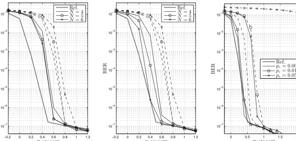
In Fig. 8 (left) the performance of FT and conventional Turbo decoder are compared forpe=0.01, where both de-coders employ NBC. The number of quantization bits is var-ied from 4 to 6, that is N=4,5,6. First of all it can be observed, that the additional distortion due to the memory channel increases the decoding threshold, but does not af-fect the error floor – thus it acts like a decreased SNR on the communications channel as noted before. When comparing both decoders, it can be noticed that the FT decoder
outper-0.001 0.001
0.001
0.001
0.005
0.005
0.005 0.005
0.01 0.01
0.01
0.02 0.02
0.02
0.04 0.04
0.04
0.06 0.06
0.08 0.08
0.1
0.1
D
ec
o
d
er
1
I
(
X
;
ΛE
)
-D
ec
o
d
er
2
I
(
X
;
Λ
)
Decoder 1I(X;Λ) - Decoder 2I(X;ΛE)
0 0.1 0.2 0.3 0.4 0.5 0.6 0.7 0.8 0.9 1
0 0.1 0.2 0.3 0.4 0.5 0.6 0.7 0.8 0.9 1
Ref.
Π∗
ΠNBC
Fig. 7.EXIT chart for NBC and optimized index assignment for
N= 6(pe= 0.01,Eb/N0= 0.25dB, FT decoder).
in quantizer output. Exploitation of this redundancy requires
the FT decoder though.
450
As suggested by Fig. 4 (
left
) a higher quantization width
and an optimized index assignment w.r.t. (18) can yield
fur-ther improvement. Figs. 6 and 7 fur-therefore compare EXIT
charts of the FT decoder for NBC (
ΠNBC
) and optimized
index assignments (
Π
∗). In Fig. 6 a quantization width of
455
N
= 4
is employed. The limited redundancy in
R
and smaller
degrees of freedom during the optimization do not allow for
any gain of the optimized index assignment over NBC in this
case. Both charts are identical. But with
N
increased by two
Bit, the optimization becomes more effective as shown in
460
Fig. 7. The tunnel nearly approaches the reference,
indicat-ing that the decoder will converge with less iterations than in
the NBC case.
A general observation from the presented EXIT charts is
that an unreliable receive buffer leads to degradation in the
465
lower to medium part of the chart. This is due to the fact
that during the ongoing decoding process the extrinsic LLRs
become more important than the received values. Regarding
the BER performance, we thus expect a degradation of
de-coding threshold but only marginal impact on the error floor,
470
because low BERs are represented by the very upper part of
the chart, where the received values only have small impact.
3.4
BER
Fig. 8 shows performance results for a Turbo decoder with
unreliable receive buffer in terms of the BER. The scaling
475
factor
γ
is computed as a linear function of
E
b/N
0. The
co-efficients of this function have been found by linear fit of the
solution of (20) for a suitable range of
E
b/N
0and for each of
the considered index assignments (cf. Geldmacher and G¨otze
(2012)).
480
coders employ NBC. The number of quantization bits is
var-ied from 4 to 6, that is
N
= 4
,
5
,
6
. First of all it can be
observed, that the additional distortion due to the memory
485
channel increases the decoding threshold, but does not
af-fect the error floor – thus it acts like a decreased SNR on the
communications channel as noted before. When comparing
both decoders, it can be noticed that the FT decoder
outper-forms the conventional decoder. Furthermore it can be seen
490
that an increased quantization width slightly improves
error-resilience: Baseline performance is approached earlier if 5 or
6 Bit are employed instead of only 4 Bit.
To take into account the impact of the index assignment we
now compare performance of the FT decoder with optimized
495
index assignment and the conventional decoder with NBC.
For
p
e= 0
.
01
, the plot in Fig. 8 (
middle
) shows the influence
of an increased quantization width for this scenario. A
sig-nificantly improved performance can be observed for the FT
decoder with higher quantization width: Actually, for
N
= 6
500
the FT decoder completely compensates the disturbance due
to the memory channel for BERs smaller than
10
−5, since
the higher redundancy involved with the larger quantization
width can be exploited more efficiently by the index
assign-ment optimization. This is in accord with the conclusion from
505
the EXIT chart analysis in the previous section.
The impact of the error probability
p
eis shown in Fig. 8
(
right
) for
N
= 6
. Taking a BER working point of
10
−5it
can be seen that error rates of
p
e= 0
.
005
and
p
e= 0
.
01
are
completely compensated by the FT decoder with optimized
510
index assignment, while for
p
e= 0
.
05
a loss of about
0
.
4dB
can be observed. The performance of the conventional
de-coder on the other hand is significantly degraded.
In order to quantify the loss of coding gain
∆
E
b/N
0as-sociated with a certain
p
eat a given working point, Fig. 9
515
compares the performance of a conventional decoder and a
FT decoder with each
N
= 4
Bit and NBC, and a FT
de-coder with
N
= 6
and optimized index assignment. Taking
for example a relatively strong memory channel distortion
of about
p
e= 0
.
05
it can be seen that the conventional
de-520
coder with NBC and
N
= 4
requires an additional
1
.
7dB
to
achieve a BER of
10
−5compared to a Turbo decoder with
error-free buffer memory. Employing the FT decoder with
N
= 4
and NBC reduces this loss to about
0
.
95dB
. Further
improvement is achieved by spending 2 additional Bits and
525
employing an optimized index assignment: In this case the
loss of coding gain is reduced to
0
.
4dB
. It general it can be
observed from the figure that the latter configuration
outper-forms the first two and can even completely compensate the
impact of the memory channel for
p
eup to
1%
. If only
N
= 4
530
Bit are employed, there still is a benefit from the FT decoder
for
p
e≥
0
.
005
, since it reduces the loss of coding gain by
about
40%
to
50%
.
Figure 7. EXIT chart for NBC and optimized index assignment forN=6 (pe=0.01,Eb/N0=0.25 dB, FT decoder).
forms the conventional decoder. Furthermore it can be seen that an increased quantization width slightly improves error-resilience: Baseline performance is approached earlier if 5 or 6 Bit are employed instead of only 4 Bit.
To take into account the impact of the index assignment we now compare performance of the FT decoder with optimized index assignment and the conventional decoder with NBC. Forpe=0.01, the plot in Fig. 8 (middle) shows the influence of an increased quantization width for this scenario. A sig-nificantly improved performance can be observed for the FT decoder with higher quantization width: Actually, forN=6 the FT decoder completely compensates the disturbance due to the memory channel for BERs smaller than 10−5, since the higher redundancy involved with the larger quantization width can be exploited more efficiently by the index assign-ment optimization. This is in accord with the conclusion from the EXIT chart analysis in the previous section.
The impact of the error probabilitypeis shown in Fig. 8 (right) forN=6. Taking a BER working point of 10−5 it can be seen that error rates ofpe=0.005 andpe=0.01 are completely compensated by the FT decoder with optimized index assignment, while forpe=0.05 a loss of about 0.4 dB can be observed. The performance of the conventional de-coder on the other hand is significantly degraded.
In order to quantify the loss of coding gain1Eb/N0
as-sociated with a certainpe at a given working point, Fig. 9 compares the performance of a conventional decoder and a FT decoder with eachN=4 Bit and NBC, and a FT decoder withN=6 and optimized index assignment. Taking for ex-ample a relatively strong memory channel distortion of about pe=0.05 it can be seen that the conventional decoder with NBC andN=4 requires an additional 1.7 dB to achieve a BER of 10−5 compared to a Turbo decoder with error-free buffer memory. Employing the FT decoder withN=4 and
−0.2 0 0.2 0.4 0.6 0.8 1 1.2 10−7
10−6 10−5 10−4 10
−3
10
−2
Eb/N0[dB]
B
E
R
−0.2 0 0.2 0.4 0.6 0.8 1 1.2 10−7
10−6 10−5 10−4 10
−3
10
−2
Eb/N0[dB]
B
E
R
0 0.5 1 1.5 2
10−7 10−6 10−5 10−4 10−3 10−2
Eb/N0[dB]
B
E
R Ref.pe= 0.005
pe= 0.01
pe= 0.05
Fig. 8.Left:Conventional (”−−“) vs. FT (”−“) decoder (pe= 0.01, NBC). Middle, right: NBC with conventional decoder (”−−“) vs.
optimized index assignment with FT decoder (”−“) (pe= 0.01(middle),N= 6(right))
10−3 10−2 10−1
−0.5 0 0.5 1 1.5 2 2.5 3 3.5
pe
∆
Eb
/N
0
[
d
B
]
N= 4,ΠNBC, LogMAP
N= 4,ΠNBC, FTMAP
N= 6,Π∗, FTMAP
Fig. 9.Loss of coding gain for a target BER of10−5as a function ofp
efor different scenarios.
4
Conclusions
Increasing integration depths of integrated circuits may lead
535
to higher susceptibility against process variations and soft
error events. Similarly, aggressive voltage scaling can yield
unreliable operation of logic and memory of an integrated
circuit. Developing signal processing algorithms that can to
some extend deal with unreliable underlying hardware is thus
540
an emerging problem. In this paper a Turbo decoder with an
unreliable receive buffer was studied. This buffer is modeled
as a binary symmetric channel that acts on the quantized
re-ceived values. It can thus be seen as an additional discrete
memoryless channel that is cascaded to the actual
communi-545
cation channel. The interaction of both channels, represented
by quantizer and index assignment, was identified as an
im-portant impact factor on the resilience of the Turbo decoder
against errors originating from the memory channel. For a
decoder with a transition metric adapted to the actual
sta-550
tistical model of the channel cascade, a joint optimization
of both components yields improved error-resilience without
increasing the computational complexity of the decoder.
References
Abdallah, R. and Shanbhag, N.: Error-Resilient Low-Power Viterbi
555
Decoder Architectures, IEEE Transactions on Signal Processing, 57, 4906–4917, 2009.
Alles, M., Brack, T., and Wehn, N.: A Reliability-Aware LDPC Code Decoding Algorithm, in: IEEE 65th Vehicular Technology Conference (VTC2007-Spring), pp. 1544–1548, 2007.
560
Figure 8. Left: Conventional (“−−”) vs. FT (“−”) decoder (pe=0.01, NBC). Middle, right: NBC with conventional decoder (“−−”) vs. optimized index assignment with FT decoder (“−”) (pe=0.01 (middle),N=6 (right)).
8 J. Geldmacher et al.: Improved Fault Tolerance of Turbo Decoding
−0.2 0 0.2 0.4 0.6 0.8 1 1.2 10−7
10−6 10−5 10−4 10−3 10−2 10−1
Eb/N0[dB]
B
E
R
Ref.
N= 4
N= 5
N= 6
−0.2 0 0.2 0.4 0.6 0.8 1 1.2 10−7
10−6 10−5 10−4 10−3 10−2 10−1
Eb/N0[dB]
B
E
R
Ref.
N= 4
N= 5
N= 6
0 0.5 1 1.5 2
10−7 10−6 10−5 10−4 10−3 10−2 10−1
Eb/N0[dB]
B
E
R Ref.pe= 0.005
pe= 0.01
pe= 0.05
Fig. 8.Left:Conventional (”−−“) vs. FT (”−“) decoder (pe= 0.01, NBC).Middle, right: NBC with conventional decoder (”−−“) vs.
optimized index assignment with FT decoder (”−“) (pe= 0.01(middle),N= 6(right))
10−3 10−2 10−1
−0.5 0 0.5 1 1.5 2 2.5 3 3.5
pe
∆
Eb
/N
0
[
d
B
]
N= 4,ΠNBC, LogMAP
N= 4,ΠNBC, FTMAP
N= 6,Π∗, FTMAP
Fig. 9.Loss of coding gain for a target BER of10−5as a function ofp
efor different scenarios.
4 Conclusions
Increasing integration depths of integrated circuits may lead
535
to higher susceptibility against process variations and soft error events. Similarly, aggressive voltage scaling can yield unreliable operation of logic and memory of an integrated circuit. Developing signal processing algorithms that can to some extend deal with unreliable underlying hardware is thus
540
an emerging problem. In this paper a Turbo decoder with an unreliable receive buffer was studied. This buffer is modeled as a binary symmetric channel that acts on the quantized re-ceived values. It can thus be seen as an additional discrete memoryless channel that is cascaded to the actual
communi-545
cation channel. The interaction of both channels, represented by quantizer and index assignment, was identified as an
im-portant impact factor on the resilience of the Turbo decoder against errors originating from the memory channel. For a decoder with a transition metric adapted to the actual
sta-550
tistical model of the channel cascade, a joint optimization of both components yields improved error-resilience without increasing the computational complexity of the decoder.
References
Abdallah, R. and Shanbhag, N.: Error-Resilient Low-Power Viterbi 555
Decoder Architectures, IEEE Transactions on Signal Processing, 57, 4906–4917, 2009.
Alles, M., Brack, T., and Wehn, N.: A Reliability-Aware LDPC Code Decoding Algorithm, in: IEEE 65th Vehicular Technology Conference (VTC2007-Spring), pp. 1544–1548, 2007. 560
Figure 9. Loss of coding gain for a target BER of 10−5as a function ofpefor different scenarios.
NBC reduces this loss to about 0.95 dB. Further improvement is achieved by spending 2 additional Bits and employing an optimized index assignment: In this case the loss of coding gain is reduced to 0.4 dB. It general it can be observed from the figure that the latter configuration outperforms the first two and can even completely compensate the impact of the memory channel for pe up to 1 %. If only N =4 Bit are employed, there still is a benefit from the FT decoder for pe≥0.005, since it reduces the loss of coding gain by about 40 % to 50 %.
4 Conclusions
Increasing integration depths of integrated circuits may lead to higher susceptibility against process variations and soft error events. Similarly, aggressive voltage scaling can yield unreliable operation of logic and memory of an integrated circuit. Developing signal processing algorithms that can to some extend deal with unreliable underlying hardware is thus an emerging problem. In this paper a Turbo decoder with an unreliable receive buffer was studied. This buffer is modeled as a binary symmetric channel that acts on the quantized received values. It can thus be seen as an additional discrete memoryless channel that is cascaded to the actual communication channel. The interaction of both channels, represented by quantizer and index assignment, was identified as an important impact factor on the resilience of the Turbo decoder against errors originating from the memory channel. For a decoder with a transition metric adapted to the actual statistical model of the channel cascade, a joint optimization of both components yields improved error-resilience without increasing the computational com-plexity of the decoder.
Edited by: W. Mathis
Reviewed by: two anonymous referees
References
Abdallah, R. and Shanbhag, N.: Error-Resilient Low-Power Viterbi Decoder Architectures, IEEE T. Signal Proces., 57, 4906–4917, 2009.
Alles, M., Brack, T., and Wehn, N.: A Reliability-Aware LDPC Code Decoding Algorithm, in: IEEE 65th Vehicular Technology Conference (VTC2007-Spring), 1544–1548, 2007.
Azami, S. B. Z., Duhamel, P., and Rioul, O.: Joint Source-Channel Coding: Panorama of Methods, in: Proc. of CNES Workshop on Data Compression, 1996.
Bahl, L., Cocke, J., Jelinek, F., and Raviv, J.: Optimal decoding of linear codes for minimizing symbol error rate, IEEE T. Inform. Theory, 20, 284–287, 1974.
Baumann, R.: Soft errors in advanced computer systems, IEEE Des. Test Comput., 22, 258–266, 2005.
Borkar, S.: Designing reliable systems from unreliable components: the challenges of transistor variability and degradation, IEEE Mi-cro, 25, 10–16, 2005.
Brehm, C., May, M., Gimmler, C., and Wehn, N.: A Case Study on Error Resilient Architectures for Wireless Communication, in: Architecture of Computing Systems (ARCS 2012), 7179, 13–24, 2012.
Cover, T. and Thomas, J.: Elements of Information Theory, Wiley, 1991.
Djahromi, A. K., Eltawil, A. M., Kurdahi, F. J., and Kanj, R.: Cross Layer Error Exploitation for Aggressive Voltage Scaling, in: 8th Int. Symp. on Quality Electronic Design (ISQED ’07), 192–197, 2007.
Farvardin, N.: A study of vector quantization for noisy channels, IEEE T. Inform. Theory, 36, 799–809, 1990.
Geldmacher, J. and Götze, J.: On Fault Tolerant Decoding of Turbo Codes, in: International Symposium on Turbo Codes & Itera-tive Information Processing (ISTC2012), Gothenburg, Sweden, 2012.
Geldmacher, J. and Götze, J.: EXIT-Optimized Index Assignments for Turbo Decoders with Unreliable LLR Transfer, IEEE Com-mun. Lett., 17, 992–995, 2013.
Ghosh, S. and Roy, K.: Parameter Variation Tolerance and Error Re-siliency: New Design Paradigm for the Nanoscale Era, P. IEEE, 98, 1718–1751, 2010.
Gimmler-Dumont, C., Brehm, C., and Wehn, N.: Reliability study on system memories of an iterative MIMO-BICM system, in: IEEE/IFIP 20th International Conference on VLSI and System-on-Chip (VLSI-SoC), 255–258, 2012.
Hegde, R. and Shanbhag, N.: Soft digital signal processing, IEEE T. VLSI Syst., 9, 813–823, 2001.
Hussien, A., Khairy, M., Khajeh, A., Eltawil, A., and Kurdahi, F.: Combined Channel and Hardware Noise Resilient Viterbi De-coder, in: Asilomar Conf. on SS&C, Pacific Grove, CA, 2010. Hussien, A., Khairy, M., Khajeh, A., Eltawil, A., and Kurdahi, F.: A
Class of Low Power Error Compensation Iterative Decoders, in: IEEE Global Telecommunications Conference (GLOBECOM 2011), Houston, TX, USA, 2011.
Karakonstantis, G., Roth, C., Benkeser, C., and Burg, A.: On the exploitation of the inherent error resilience of wireless systems under unreliable silicon, in: Proceedings of the 49th Annual De-sign Automation Conference, DAC ’12, 510–515, New York, NY, USA, 2012.
Khajeh, A., Amiri, K., Khairy, M., Eltawil, A., and Kurdahi, F.: A Unified Hardware and Channel Noise Model for Communi-cation Systems, in: IEEE Global CommuniCommuni-cations Conference (GLOBECOM 2010), 2010.
Khairy, M. S., Shen, C.-A., Eltawil, A. M., and Kurdahi, F.: Error resilient MIMO detector for memory-dominated wireless com-munication systems, in: IEEE Global Comcom-munications Confer-ence (GLOBECOM), 3566–3571, 2012.
Kleeberger, V. B., Gimmler-Dumont, C., Weis, C., Herkersdorf, A., Mueller-Gritschneder, D., Nassif, S. R., Schlichtmann, U., and Wehn, N.: A cross-layer technology-based study of how memory errors impact system resilience, IEEE Micro, 33(4), 46–55, 2013. Liu, Y., Zhang, T., and Hu, J.: Design of Voltage Overscaled Low-Power Trellis Decoders in Presence of Process Variations, IEEE T. VLSI Syst., 17, 439–443, 2009.
Makhzan, M., Khajeh, A., Eltawil, A., and Kurdahi, F.: Limits on voltage scaling for caches utilizing fault tolerant techniques, in: 25th International Conference on Computer Design (ICCD 2007), 488–495, 2007.
May, M., Alles, M., and Wehn, N.: A case study in reliability-aware design: a resilient LDPC code decoder, in: Proceedings of the Conference on Design, Automation and Test in Europe (DATE ’08), 456–461, New York, NY, USA, 2008.
Mitra, S., Seifert, N., Zhang, M., Shi, Q., and Kim, K.: Robust sys-tem design with built-in soft-error resilience, Computer, 38, 43– 52, 2005.
Mitra, S., Brelsford, K., and Sanda, P.: Cross-layer resilience chal-lenges: Metrics and optimization, in: Design, Automation Test in Europe Conference Exhibition (DATE), 1029–1034, 2010. Mitra, S., Brelsford, K., Kim, Y., Lee, H., and Li, Y.: Robust System
Design to Overcome CMOS Reliability Challenges, IEEE Jour-nal of Emerging and Selected Topics in Circuits and Systems, 1, 30–41, 2011.
Novak, C., Studer, C., Burg, A., and Matz, G.: The effect of un-reliable LLR storage on the performance of MIMO-BICM, in: Asilomar Conf. on SS&C, 736–740, 2010.
Reeves, C. (Ed.): Modern heuristic techniques for combinatorial problems, John Wiley & Sons, Inc., New York, NY, USA, 1993. Roth, C., Benkeser, C., Studer, C., Karakonstantis, G., and Burg, A.: Data mapping for unreliable memories, in: 50th Annual Allerton Conference on Communication, Control, and Computing, 2012. Shanbhag, N., Abdallah, R., Kumar, R., and Jones, D.: Stochastic computation, in: 47th ACM/IEEE Design Automation Confer-ence (DAC), 859–864, 2010.