Please cite this article as: S. Mahjouri, R. Shabani, G. Rezazadeh, Vibration Analysis of an Air Compressor Based on A Hypocycloidal Mechanism: an Experimental Study, International Journal of Engineering (IJE), TRANSACTIONS B: Applications Vol. 28, No. 11, (November 2015) 1687-1692
International Journal of Engineering
J o u r n a l H o m e p a g e : w w w . i j e . i r
Vibration Analysis of an Air Compressor Based on a Hypocycloidal Mechanism: an
Experimental Study
S. Mahjouri, R. Shabani*, G. Rezazadeh
Mechanical engineering Department, Urmia University, Urmia, Iran
P A P E R I N F O
Paper history:
Received 29 June 2015
Received in revised form 25 August 2015 Accepted 19 November 2015
Keywords: Hypocycloid Dynamic Balancing Reciprocating Compressor
A B S T R A C T
In this paper, the experimental vibration analysis of a single cylinder air compressor based on a hypocycloid straight line mechanism (HSM) is investigated. The HSM mechanism uses planetary gears to convert rotational motion to purely linear motion. In the conventional air compressor, the slider- crank mechanism is replaced by the HSM mechanism with appropriate counterweights. The constructed setup is fixed over a base plate supported by an elastic foundation and is driven by a speed-controlled electric motor. During the experiments, the driving frequency is varied and the vibrations of the base plate due to unbalanced forces are recorded in three directions. The results are compared with the experimental results of a compressor based on the conventional slider-crank mechanism. Time and frequency domain analyses indicated that the mechanism can be balanced effectively, and the shaking force and induced vibrations can be significantly suppressed.
doi: 10.5829/idosi.ije.2015.28.11b.18
1. INTRODUCTION1
The slider-crank mechanism developed one hundred years ago is still used today in many high-speed machines. The simplicity of the mechanism promotes its employment in many applications, such as internal combustion engines, some air compressor types, and pumps. However, it has been proven that the slider-crank cannot produce a purely or symmetrical reciprocating motion. In addition, because of the gyrating motions of the connecting rod, dynamic balancing of the slider-crank is a serious problem, possible only by using complex linkage mechanisms. The general planer-type motion of the connecting rod produces piston side loads which increase the amount of friction force between the piston and the walls of the cylinder holding it. Different methods have been developed for dynamic balancing of the mechanism [1, 2], but the complexity and restrictions of some proposed methods have caused new approaches to be reported. Balancing based on imposing counterweights to the
1*Corresponding Author’s Email: [email protected] (R. Shabani)
based on the copying properties of the pantograph and parallelogram mechanism [8]. This method involves connecting a two-link group, forming a pantograph with the crank and coupler, to the mechanism to be balanced. In addition, balancing the shaking force and moment of the slider-crank mechanism has been achieved using two identical slider–crank mechanisms which are executed in a similar manner but in opposite directions [9]. The slider-crank mechanism has also been balanced employing planetary systems [8, 10] and a cable and pulley arrangement [11]. Cam mechanism is the other technique used to balance the slider-crank mechanism [12, 13]. In other words, the shaking force and moment are cancelled via a cam mechanism carrying a counterweight, and the cam-driven masses are employed to keep the center of the mechanism’s mass stationary. Based on the cam-spring mechanism for minimizing input torque fluctuations, Arakelian and Briot proposed a method for balancing the shaking force and shaking moment in the slider-crank mechanism [14]. Imposing a second cam to the input crank, they developed an instrument to balance both shaking force and moment. Employing multiple cylinders with static counterweights in the crank shaft is another method for balancing the slider-crank mechanism; however, the vibrations of the compound mechanism could cause a considerable amount of power to be lost.
To surmount the aforementioned restrictions, some researchers proposed a different mechanism which converts the purely rotational motion of the input shaft to a linear reciprocating motion in the connecting rod [15-17] and vice versa. This is known as the hypocycloid mechanism (HSM). This mechanism includes a fixed gear ring (or gear) and a planetary gear (or pinion). When the pinion rolls inside the gear, a point on the pitch circle of the pinion generates a curve called a hypocycloid. When the diameter of the pinion is one half that of the gear, the curve traced by a point on the pitch circle of the pinion is an exact straight line. This principle is used to design a planetary gear pair to produce a reciprocating motion with no gyrating motion in the connecting rod.
To the authors’ best knowledge, there is no experimental result concerning the dynamic test and force balancing of the HSM mechanism in the literature. The present study, for the first time, examines the
dynamic balancing of the HSM mechanism
experimentally. Employing an HSM mechanism in an air compressor, the dynamic balancing of the mechanism was evaluated. In a conventional air compressor the slider-crank was replaced by the HSM mechanism with appropriate counterweights. The setup was fixed over a base plate supported by an elastic foundation. Then, employing a variable speed motor, the compressor was driven with different angular velocities, and the vibrations of the base plate recorded in three directions. Acceleration records of the HSM
mechanism were compared with test results of an equivalent compressor based on the conventional slider crank mechanism. In the experimental setups, the effects of the compressed air flow as an unbalancing force were ignored. Results showed that utilizing the balanced HSM mechanism notably suppressed the shaking forces and consequently the vibrations of the system. The test results were compared in time and frequency domains.
2. EXPERIMRNTAL SETUP AND THE RESULTS
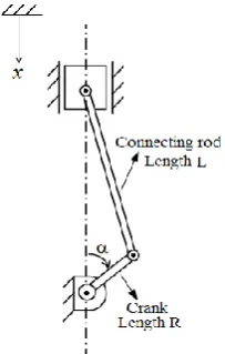
Prior to explaining the experimental setup, the kinematic diagrams of the conventional slider-crank and the HSM mechanism were compared. Schematic views of the slider-crank and HSM mechanisms are shown in Figs. 1 and 2, respectively. In the conventional slider-crank mechanism, the piston side loads are reduced by selecting the length of connecting rod L as more than two times that of crank arm R. Consequently, the displacement of the slider will not be a purely harmonic motion and is described by the following equation:
2 2 2
(1 1 R sin )+ (1 )
x L R cos
L
(1)
where x is the displacement of the piston and α the crank angle. Due to the complicated structure of the reciprocating equation and the gyrating motions of the connecting rod, the dynamic balancing of the mechanism is difficult. In this mechanism if the connecting rod length is equal to that of the crank arm (L=R), the motion will be a purely harmonic one :
2 (1 )
x R cos (2)
lateral load between the pinion and the gear are eliminated. In the HSM mechanism, the displacements of points P and E are represented as:
2
2 p
E
x Rcos x Rsin
(3)
A schematic view of the experimental setup is shown in Fig. 3. It includes the HSM mechanism with the appropriate balancing weights. It converts the purely rotational motion of the input crank to a purely harmonic linear motion of the connecting rod and consequently of the piston. In the experimental setup for symmetry, greater stability of the system, and the elimination of unwanted shaking moments, double HSM mechanisms with balancing weights are constructed and assembled to carry the connecting rod and the piston (see the side view in Figure 3).
Details of the dimensions and specifications of the conventional slider-crank and the HSM mechanism used in this study are listed in Table 1. It should be noted that replacing the HSM mechanism within the crank cases of a conventional compressor caused the stroke of the HSM mechanism to increase to 46 mm and, consequently, (because of the fixed height of the holding cylinder) the height of the piston and its weight were decreased.
Balancing the HSM mechanism took place in two steps. At first, to eliminate the shaking force induced by the connecting rod and the piston, a counterweight mE is attached to the pinion on the side opposite point P (Figure. 3). Therefore, two components of shaking forces could be addressed. The shaking force induced by the connecting rod and piston acts in a vertical direction, and that related to the imposed counterweight mE in a horizontal direction. In the second step, another counterweight mC is attached to the crank shaft to eliminate the shaking forces resulting from the first step. Taking into account the locations of the counterweights, their masses have the following relations:
2
2 2
E L p
C L p pi
m m m
m m m m
(4)
where mL, mp, and mpi denote the weights of connecting rod, piston, and pinion, respectively. The performance of the imposed counterweights or dynamic balancing of the constructed HSM mechanism was evaluated by measuring the induced vibrations due to unbalanced forces. To this end, a compressor based on the balanced HSM mechanism and another compressor based on the conventional slider-crank mechanism were tested sequentially. They were fixed over a base plate with an elastic foundation and driven with a variable speed motor. The elastic foundation includes six helical spring with total stiffness of 240 KN/m. Overall weight of the moving parts including the motor, compressor and base
plate masses is 24 kg and the bouncing natural frequency of the system is about 100 rad/sec. Pictures of each setup are shown in Figures 4 and 5, respectively.
Figure 1. Schematic view of the conventional slider-crank mechanism.
Figure 2. Schematic view of the HSM mechanism
TABLE 1. Dimensions and specifications of the experimental setup
Electric motor Power (Kw) 0.75
Driving speed (rpm) 0-1250
Piston diameter (mm) 65
Slider crank
Stroke (mm) 40
Volume (cc) 133
Piston weight(gr) 295
Connecting rode weight(gr) 90
HSM
Stroke (mm) 46
Volume (cc) 153
Pinion pitch diameter (mm) 23
Gear diameter (mm) 46
Piston weight mp(gr) 266
Connecting rode weight mL (gr) 64
Pinion weight mpi(gr) 58
Counter weight 'mE' (gr) 2×165 Counter weight 'mC' (gr) 2×223
Figure 4. Experimental setup based on conventional slider crank mechanism.
Figure 5. Experimental setup based on the balanced HSM mechanism.
Driving both mechanisms at up to 1250 rpm induced vibrations of the base plate due to shaking force, and moments are recorded in three orthogonal x, y, and z directions. The normal direction to the base plate is assigned as the z axis, and x and y axes are in the plane of the base plate and orthogonal to each other.
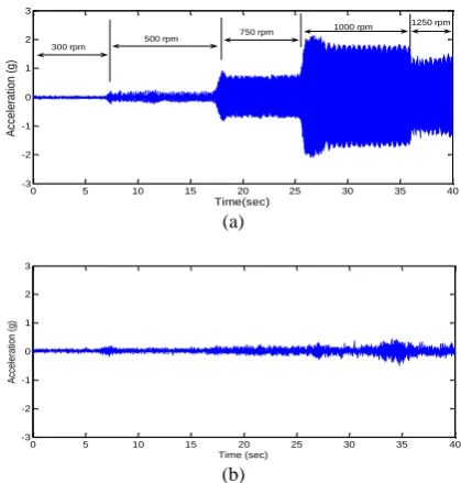
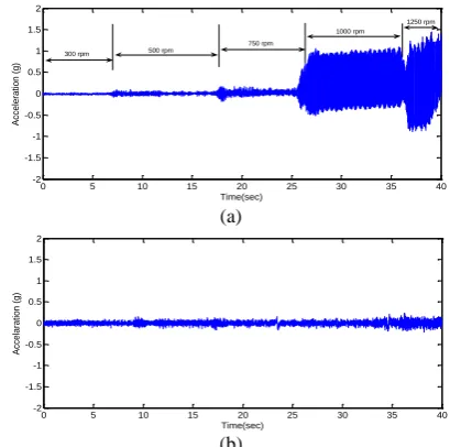
It should be noted that, during the tests, the output pressure pipe was disconnected from the storage tank, and the effect of the output air pressure on the dynamic forces was neglected. Throughout each test, the angular velocity of the input crank was varied steeply, and the accelerations of the base plate were recorded in three directions. Employing the conventional slider-crank mechanism, the time history of the base plate acceleration in z direction is shown in Fig. 6a. It is depicted that the shaking force increased with increases in velocity, especially when the driving frequency was close to the bouncing natural frequency of the system. Peak acceleration amplitude of 2g was recorded when the forcing frequency was about 1000 rpm. Fig. 6b shows the acceleration of the base plate in z direction where the slider-crank was replaced by the new balanced HSM mechanism. Results revealed that the shaking force and the induced vibrations were effectively suppressed. The emergent low level of acceleration, "up to 0.2 g", could be related to the imprecision of the constructed elements, which is inevitable. During each test, in addition to the acceleration in z direction, the acceleration components in x and y directions were also recorded. Due to effective balancing of the HSM mechanism, it was seen that the vibrations were also significantly suppressed in x and y directions (Figures 7 and 8).
(a)
(b)
Figure 6. Comparison of the base plate accelerations in 'z' direction for different angular velocities, a) Conventional slider-crank mechanism, b) Proposed HSM mechanism.
0 5 10 15 20 25 30 35 40
-3 -2 -1 0 1 2 3
Time(sec)
Ac
ce
le
ra
tio
n
(g
)
300 rpm
500 rpm 750 rpm
1000 rpm 1250 rpm
0 5 10 15 20 25 30 35 40
-3 -2 -1 0 1 2 3
Time (sec)
Acc
ele
ratio
n (g
Table 2 gives the root mean square ‘RMS’ of the recorded accelerations that is related to the consuming energy in the system. The results show that the RMS values of the accelerations are suppressed effectively in the proposed mechanism. A comparison of the test results is also reported in frequency domain. Taking into account the acceleration components in z direction, the frequency spectrum of the conventional and HSM mechanisms are shown in Fig. 9. It was seen that the frequency content of the conventional mechanism included distinct forcing frequencies. Some low energy levels of vibrations were also included in the frequency content. These frequencies could be related to transient vibrations and/or higher harmonics of the shaking forces in the slider-crank mechanism; however, all of the components were suppressed in the balanced HSM system.
In spite of the exact balancing of the HSM mechanism, some low-levels vibrations also emerged in the results. These vibrations could be related to exhaust air and some imprecision of the constructed gears and pinions, which were unavoidable in the present study (Figs. 6b, 7b, and 8b). This mechanism could be used in internal combustion engines to reduce fuel consumption and conserve considerable energy compared to the conventional slider-crank mechanism. However, in comparing the proposed HSM mechanism with the conventional slider-crank mechanism, complexity was seen as the main drawback of the proposed HSM mechanism.
(a)
(b)
Figure 7. Comparison of the base plate accelerations in 'y' direction for different angular velocities, a) Conventional slider-crank mechanism, b) Proposed HSM mechanism.
(a)
(b)
Figure8. Comparison of the base plate accelerations in 'x' direction for different angular velocities, a) Conventional slider-crank mechanism, b) Proposed HSM mechanism.
TABLE 2. Root mean square ‘RMS’ values of the acceleration records.
Direction Conventional mechanism HSM mechanism
Z 0.7562 0.0868
x 0.3753 0.0524
y 0.2245 0.0506
Figure 9. Comparison of the frequency spectrum of the slider-crank and proposed HSM mechanism in z direction.
3. CONCLUSION
Despite many efforts to balance the slider-crank mechanism, it was not possible to be balanced exactly except by using complex mechanisms and linkages. As an alternative, a new HSM mechanism is proposed which converts a purely rotational motion to a purely linear motion without any gyrating in the connecting rod and which can be balanced effectively. Employing the HSM mechanism, a single cylinder air compressor was made and balanced using appropriate counterweights. The apparatus was installed over an elastic foundation
0 5 10 15 20 25 30 35 40
-2 -1.5 -1 -0.5 0 0.5 1 1.5 2
Time(sec)
Acc
ele
ratio
n (g
)
300 rpm
500 rpm 750 rpm
1000 rpm
1250 rpm
0 5 10 15 20 25 30 35 40
-2 -1.5 -1 -0.5 0 0.5 1 1.5 2
Time(sec)
Acc
ele
ratio
n (g
)
0 5 10 15 20 25 30 35 40
-2 -1.5 -1 -0.5 0 0.5 1 1.5 2
Time(sec)
Acc
ele
ratio
n (g
)
300 rpm 500 rpm
750 rpm
1000 rpm 1250 rpm
0 5 10 15 20 25 30 35 40
-2 -1.5 -1 -0.5 0 0.5 1 1.5 2
Time(sec)
Acc
ela
ratio
n (g
)
0 500 1000 1500
0 1000 2000 3000 4000 5000 6000
Driving Frequency (rpm)
Sp
ect
rum
in which its performance was studied by recording the shaking force induced vibrations in three directions. Deapite some imperfections in the constructed gear assembly, results showed that the mechanism could be balanced effectively, and the side loads on the piston and the shaking loads could be significantly eliminated. The balanced HSM mechanism can be used in internal combustion engines to reduce fuel consumption and conserve considerable energy, compared with the conventional slider-crank mechanism.
4. REFERENCES
1. Bagci, C., "Shaking force and shaking moment balancing of the plane slider crank mechanism", in Proceedings of the 4th OSU Applied Mechanisms Conference. (1975), 25.21-25.16. 2. Arakelian, V.H. and Smith, M., "Shaking force and shaking
moment balancing of mechanisms: A historical review with new examples", Journal of Mechanical design, Vol. 127, No. 2, (2005), 334-339.
3. Gheronimus, Y.L., "An approximate method of calculating a counterweight for the balancing of vertical inertia forces", Journal of Mechanisms, Vol. 3, No. 4, (1969), 283-288. 4. Campbell, D. N.,”balanced slider-crank mechanism” Patent FR
2421301, (1979).
5. Lanchester F.M., “ Engine balancing”, Horseless Age, vol. 33, no. 12–16, (1914).
6. Arakelian, V. and Makhsudyan, N., "Generalized lanchester balancer", Mechanics Research Communications, Vol. 37, No. 7, (2010), 647-649.
7. Tsai, L.-W. and Walter, R., Evaluation of the oldham-coupling
type balancer on a 2.5 liter in-line four-cylinder engine. (1984),
SAE Technical Paper.
8. Arakelian, V. and Smith, M., "Complete shaking force and shaking moment balancing of linkages", Mechanism and Machine Theory, Vol. 34, No. 8, (1999), 1141-1153.
9. Arakelian, V., "Shaking moment cancellation of self-balanced slider–crank mechanical systems by means of optimum mass redistribution", Mechanics Research Communications, Vol. 33, No. 6, (2006), 846-850.
10. Smith, M. and Ye, Z., "Complete balancing of planar linkages by an equivalent method", Mechanism and Machine Theory, Vol. 29, No. 5, (1994), 701-712.
11. Berkof, R.S., "The input torque in linkages", Mechanism and Machine Theory, Vol. 14, No. 1, (1979), 61-73.
12. Kato, H., “Mechanical pressing machine with dynamic balancing device”, Patent US5605096, (1997).
13. Schrick, P., Hanula, B., “Free inertia forces balancing piston engine”, Patent WO9526474, (1995).
14. Arakelian, V. and Briot, S., "Simultaneous inertia force/moment balancing and torque compensation of slider-crank mechanisms", Mechanics Research Communications, Vol. 37, No. 2, (2010), 265-269.
15. Wiseman, R., “Hypocycloid engine”, patent US 6,510,831 B2, (2003).
16. Lemke, J., U., McHargue, W. B., “opposed piston internal-combustion engine with hypocycloidal drive and generator apparatus”, Patent US 2007/0215093 A1, (2007).
17. Harrington, S.P., Virtual crankshaft engine. (1996), Google Patents.
Vibration Analysis of an Air Compressor Based on a Hypocycloidal Mechanism: an
Experimental Study
S. Mahjouri, R. Shabani, G. Rezazadeh
Mechanical engineering Department, Urmia University, Urmia, Iran
P A P E R I N F O
Paper history:
Received 29 June 2015
Received in revised form 25 August 2015 Accepted 19 November 2015
Keywords: Hypocycloid Dynamic Balancing Reciprocating Compressor
ديكچ ه
هلاقم نيا رد یسررب دیيولکیسوپیه میقتسم تکرح مزیناکم زا هدافتسا یانبم رب ردنلیس کت روسرپمک کي تاشاعترا زیلانآ
هدش هدنهد خرچ لماش دیيولکیسوپیه مزیناکم .تسا یاهرایس یاه
تسا یتشگرب و تفر تکرح هب ار ینارود تکرح هک
یم ليدبت سنلااب زا سپ و نيزگياج دیيولکیسوپیه مزیناکم کي اب موسرم هدنزغل و گنل مزیناکم رظن دروم روسرپمک رد .دنک
شيامزآ لماک هدش
.تسا یارب هتفرگ رارق کیتسلاا رتسب کي یور رب رظن دروم متسیس ،یداهنشیپ مزیناکم درکلمع یسررب
هرود رد هطوبرم رويارد و یکيرتکلا روتوم کي طسوت و شيامزآ فلتخم یا
هدش رد و شيامزآ یط رد .تسا یاهدماسب
یم ینازیمان یاهرواتشگ و اهورین زا یشان هک هياپ تاشاعترا فلتخم جنس باتش طسوت تهج هس رد دنشاب
هزادنا یئاه یریگ
هدش ب جياتن .دنا ه نل مزیناکم یانبم رب( یلومعم روسرپمک کي تاشاعترا تست زا لصاح جياتن اب هدمآ تسد گ
)هدنزغل
هسياقم هدش هزوح و نامز هزوح رد جياتن هسياقم .دنا دماسب
هداد ناشن تسا ب یداهنشیپ مزیناکم هک ه
نزاوتم لماک تروص
دنناوتیم هدش داجيا نزاوتمان یاهورین و هدش ًلاماک
دندرگ فذح یداهنشیپ مزیناکم طسوت