Please cite this article as: X. Sun, S. Deng, G. Chen, W. Zhang, Calculation and Analysis of Groove Elastic Support’s Radial Stiffness, International Journal of Engineering (IJE), TRANSACTIONS A: Basics Vol. 30, No. 7, (July 2017) 1066-1073
International Journal of Engineering
J o u r n a l H o m e p a g e : w w w . i j e . i rCalculation and Analysis of Groove Elastic Support’s Radial Stiffness
X. Sun*a,b, S. Dengb,c, G. Chena, W. Zhanga
a School of Mechatronics Engineering, Northwestern Polytechnical University, Xi'an, China b School of Mechatronics Engineering, Henan University of Science and Technology, Luoyang, China c Collaborative Innovation Center of Major Machine Manufacturing in Liaoning, Liaoning, China
P A P E R I N F O
Paper history:
Received 05 January 2017
Received in revised form 21 March 2017 Accepted 21 April 2017
Keywords: Groove Elastic Support Analysis Formula Radial Stiffness Structure Parameter Stiffness Homogeneit
A B S T R A C T
In this paper, an analytical formula to calculate the radial stiffness of groove elastic support is presented. The influence of structure parameters on radial stiffness and homogeneity of radial stiffness is investigated as well. The accuracy and calculating speed of the analysis formula are compared to that of finite element method (FEM). Findings are as following: The calculating speed of analysis formula is more efficient than that of finite element method (FEM). When the number of groove is less than 20, the maximum relative error of two methods is less than 10%. The radial stiffness of groove elastic support increases with the groove number, thickness of arc beam and transition angle, but decreases with the groove gap. The radial stiffness changes slightly and periodically with the azimuth angle of radial load, and the greater groove number and the thinner thickness of arc beam, the more homogeneous radial stiffness of groove elastic support.
doi: 10.5829/ije.2017.30.07a.16
1. INTRODUCTION1
In high speed rotor with the determined design scheme, it is difficult to adjust the critical speed of rotor system through changing the structure dimension [1, 2], whereas installing the elastic support with lower stiffness on the rotor system can easily reduce the critical speed and realize the rotor to be safely operated over the critical speed [3-6]. Therefore, the structure design and stiffness calculation of elastic support has become the interest to many researchers.
The stiffness formulas of typical elastic support, such as elastic ring, squirrel cage elastic, etc., based on mechanics of material theory and deduced from simplified models, are still widely used for the initial designing of typical elastic support. Ecsedi et al. [7] proposed the formulas of the torsional rigidity of the elastic ring, applying the usual assumptions of linear theory of elasticity and the Michell's theory. As stated in literature [8], an expression for the radial displacement has been derived for a thin elastic ring loaded by any combination of radial, tangential and moment loads in
*Corresponding Author’s Email: [email protected] (X. Sun)
its plane. Dai Jianxing [9] derived the elastic ring’s stiffness coefficient, and compared the result by proposed formula with that by finite element method (FEM) and the test value of stiffness shows that this analysis method is available. Cao Lei [10, 11] and Zhang Wei [12] investigated the stiffness characteristics of corrugated elastic ring by finite element method (FEM) and found that the characteristics–contact status of this elastic ring is the important factor adjusting the rotor critical speed and the deformation of this elastic ring can moderate nonlinear characteristics of elastic ring squeeze film damper (ERSFD). Hong Jie [13] adopted finite element method (FEM) to investigate the characteristics of a gas turbine engine with ERSFD and found the deformation of the elastic ring can adjust the oil film clearance. In literature [14], a metal mesh damper was designed and static stiffness was tested under different working conditons. The experimental results show that the metal mesh damper has stable support performance. Ma Yanhong [15] also used finite element method (FEM) to study an elastic ring-metal rubber damper and get the elastic support properties. Zou et al. [16] investigated the deformation and mechanical response of a rubbery metallic material and
analyzed the mesoscopic structural properties of the material and its evolution during part producing. In order to improve accuracy of support stiffness design for squirrel cage elastic support and reduce the maximal stress of squirrel cage into capacity, Wang et al. [17] proposed a kind of optimization design method based on the finite element optimization techniques. To enhance the calculation efficiency of finite element method (FEM). In this paper, the groove elastic support belongs to elastic ring. Deng et al. [18] studied the effect of structural parameters of groove elastic support on vibration characteristics of the rolling bearing combining rigid and flexible coupled method, the result shows magnitude of inner vibration can be significantly decreased with the elastic support, but the research do not refer to the stiffness calculation of the elastic support. The above mentioned research mainly focus on the stiffness calculation and structure optimizing design of corrugated elastic ring and squirrel cage elastic support. However, the study on the stiffness and structural design of the groove elastic support has not been around researcher’s interest, especially the radial stiffness of groove elastic support.
In this paper, the analytical formulas of groove elastic support’s radial stiffness are built based on mechanics of material theory, and then the calculation results are validated by finite element method (FEM). The findings provide a theoretical basis for the calculation of radial stiffness and designing of groove elastic support.
2. ANALYTICAL METHOD OF RADIAL STIFFNESS FOR GROOVE ELASTIC SUPPORT
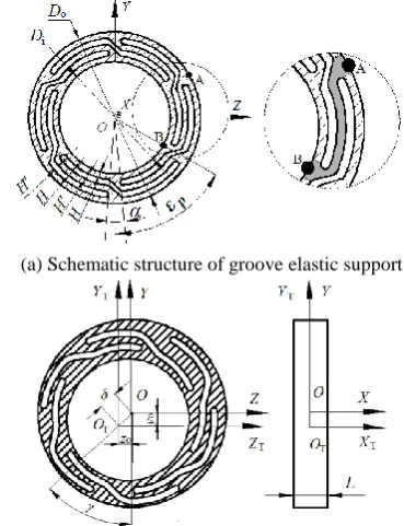
2. 1. Structure of Groove Elastic Support The groove elastic support is an atypical elastic support, which is mounted between the house and bearing’s outer ring with an interference fit. The assembly diagram of groove elastic support is shown in Figure 1. The structure and deformation of groove elastic support are illustrated in Figure 2.
In Figure 1, inertial coordinate system { ;O X Y Z, , } is fixed in the space, X axis coincides with bearing rotating axis, YOZ plane parallels the bearing radial plane passing through bearing center, and i is angular
velocity of inner ring. In Figure 2 (a), Di and Do are the
inner and outer diameters of elastic support respectively; H is thickness of the arc beam, H′ the groove gap, transition angular, A point and B point are the ends of the pth arc beam, p the azimuth angle of the pth arc beam that is the angle from the end B of arc beam to the negative half Y axis along counterclockwise direction. In Figure 2 (b), the initial position of coordinate system of elastic support center {OT;XT,Y ZT, T} coincides with { ;O X Y Z, , }, and
{OT;XT,Y ZT, T}
does not rotate but just translate in YOZ plane, δ is the radial displacement of elastic support center OT, y
o and zo are the displacement
component of δ along Y and Z axis, respectively; γ is the angle between {OT;XT,Y ZT, T} and { ;O X Y Z, , }; L is the width of the elastic support.
2. 2. Analytic Formula of Radial Stiffness In order to establish the model of elastic support’s radial stiffness, the following hypotheses are proposed:
(1) Compared with groove elastic support, outer ring of bearing is considered as a rigid body and just has a rigid displacement in OYZ plane.
(2) When the arc beam of groove elastic support bends with the radial force, the ends of arc beam A and B have no angular displacement.
(3) The bending deformation of arc beam belongs to the local small deformation which has no influence on the global dimension of groove elastic support.
Figure 1. Assembly diagram of groove elastic ring assemble
(a) Schematic structure of groove elastic support
The force and deformation on the end B of the pth arc beam in OYZ plane are shown in Figure 3. Because of interference fit between groove elastic support and bearing housing, the end A of arc beam is considered to be fixed. The other end B of arc beam moves to B′
point due to a radial force, and the displacement of B′
point is δ, which is also the displacement of outer ring's centroid.
The meaning and expression of parameters in Figure 3 are shown in Table 1
Due to the hypotheses without angular displacement at the end B, the moment Mp is neglected, and the inner
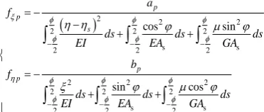
forces at the end B can be written as follows, according to the elastic center method in literature [19].
2 2 22 2 2
s s
2 2 2
2 2 2
2 2 2
s s
2 2 2
cos sin sin cos p p s p p a f
ds ds ds
EI EA GA
b f
ds ds ds
EI EA GA
(1)In Equation (1), μ is material shear factor (for the rectangular cross section μ is 1.2), E material elastic modulus, G material shear modulus, I the inertia moment of cross-section, ILH3/ 12, (ξ, η) the
coordinate of arbitrary point on the arc beam in {p,Cp,p}, Rsin,R
1 cos
;dsRd ; Asthe area of cross-section, 2 2
2 2
1 /
s ds ds
EI EI
.In Figure 4, the internal forces of point B are decomposed in { ;O X Y Z, , }, ζp is the included angle between Y axis and the chord direction of the pth arc beam, and zo and yo are the components of and can be calculated by Equation (2).
sin cos o o z y (2)
TABLE 1. Parameters’ meaning and expression in Figure 3 {ξp, Cp,
ηp }
local coordinate system of the pth arc beam
Cp midpoint of arc beam
ξp tangential direction of the arc beam
ηp perpendicular to ξpaxis
R radius of the arc beam R=Di/2+3H/2+H'
Φ span angle of arc beam
φ
included angle between the tangent of an arbitrary point on arc beam and the chord of arc beam
βp included angle between the line BBand the η ′ (δ) p axis
ap, bp ap=δsinβp , bp=δcosβp
fξp, fηp,Mp internal forces and moment of B point
ηs elastic center of arc beam
Supposing ε1 is the azimuth angle of the first arc beam,
span angle
can be written as 2 / n/ 2, n is the number of arc beam.The relationships of the geometric parameters are shown as Equation (3).
1 2( 1) /
2 2 2 arctan p p p p p o o p n z y (3)
The components of the internal forces at B point in
{ ;O X Y Z, , } are shown as Equation (4).
sin cos
cos sin
yp p p p p
zp p p p p
F f f
F f f
(4)
Since the outer ring is without rotation, theit is not necessary to calculate the moment, and then the force components of outer ring through groove elastic support are shown as Equation (5), according to the force interaction theory. 1 1 n y yp p n z zp p F F F F
(5) A B ξp B' ηs Cp ηp δ φ B B' ap bp δ fηp fξp βp Mp θ Φ s R OFigure 3. Schematic diagram of arc beam deformation and force in local coordinate system
O A fηp fξp O A B εp B' B Original Deformed Ф Ф Y Z Y Z δ
γ yo
zo M
p ηp ξp βp ap bp ζp B B' ζp
Substituting Equation (1)-(4) into Equation (5), the following expression is obtained.
s s
s s
2 2
0 0
1
2 2
0 0
1
2 2 2
2 2 2
2 2 2
2 2 2
2 2 2
2 2 2
sin cos
cos sin
sin cos
sin cos
cos sin
sin cos
n
p p
z p p
p n
p p
y p p
p
s
F y z
F y z
ds ds ds
EI EA GA
ds ds ds
EI EA GA
(6)
The radial stiffness of groove elastic support can be written as Equation (7).
cos sin
y z
F F
K
(7)
Substituting Equation (2) and Equation (6) into Equation (7), gives the following expression:
1 1
sin cos
cos sin cos
sin cos
sin cos sin
n
p p
p p
p
n
p p
p p
p
K
(8)
3. FINITE ELEMENT MODEL OF GROOVE ELASTIC SUPPORT
In order to verify the accuracy of the proposed analytic formula, the finite element model of the elastic support in Figure 5 was built in ANSYS software. It is assumed that the material is linear, and there is no plastic deformation under radial load. The finite element model is 2D with plane182 element. The mesh size is 0.5mm, the areas near the transition angles are meshed by 0.05mm. The outer surface of the elastic support is fixed in the space. All degrees of freedom of nodes on the surface are coupled to the center of the inner surface of groove elastic support, where a radial load (Fr) is
applied on.
Figure5. Finite element model of groove elastic ring
After FEM solution, the radial displacement of the inner surface of groove elastic supports can be obtained, and then the radial stiffness K can be written as
Equation (9).
r
F K
(9)
4. COMPARISONS AND ANALYSIS BETWEEN TWO METHODS
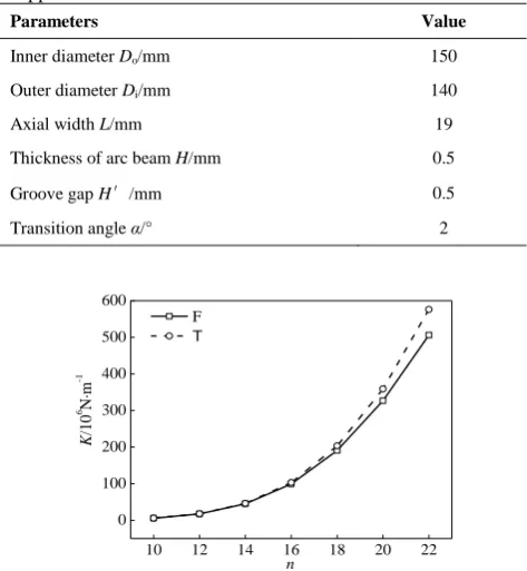
The material of groove elastic support is 8Cr4Mo4V, and the main structural parameters are shown in Table 1. According to Figure 1, the groove number n, arc beam thickness H, groove span H′ and transition angle α were chosen to investigate the radial stiffness of groove elastic support.
4. 1. Influence of Groove Number on Radial Stiffness The results of radial stiffness with different groove number n are shown in Figure 6, where T represent the analytic formula and F represent the FEM, respectively. The other structural parameters are the same values in Table 1. The radial load Fr is 500N.
Considering the carrying capacity of the support, the least groove number is 12.
In Figure 6, it can be seen that the radial stiffness for two methods increases with the groove number n.
TABLE 1. Main structural parameters of groove elastic support
Parameters Value
Inner diameter Do/mm 150
Outer diameter Di/mm 140
Axial width L/mm 19
Thickness of arc beam H/mm 0.5
Groove gap H′/mm 0.5
Transition angle α/° 2
10 12 14 16 18 20 22
0 100 200 300 400 500 600
K
/1
0
6 N
·m
-1
n F
T
The maximum of radial stiffness is less than 6.5 times the minimum when n changes from 12 to 22, and the radial stiffness calculated by the analytic formula is bigger than that calculated by FEM. The relative error between two methods increases with the groove number
n, and the relative error is lower than 10% when n is less than 22.
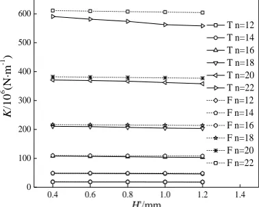
4. 2. Influence of Groove Gap on Radial Stiffness The radial stiffness with different groove gap H′ is shown in Figure 7. The other structural parameters are the same values in Table 1. The radial load Fr is 500N.
In Figure 7, the changing trends of radial stiffness by two methods are identical, and the radial stiffness decreases with the groove gap H′. When H′ changes from 0.4 mm to 1.4 mm, the radial stiffness varies in a narrow range which is less than 2%. The stiffness calculated by analytic formula is slightly higher than the value calculated by FEM. Meanwhile, the less groove number, the less relative error induced by the groove gap. When n22 and H 1.2mm, the relative error between two methods is less than 10%.
4. 3. Influence of Beam Thickness on Radial Stiffness The radial stiffness with different beam thickness H is shown in Figure 8. The other structural parameters are the same values in Table 1. The radial load Fr is 500N. In Figure 8, the radial stiffness by two
methods increases with the groove gap H. The maximum of radial stiffness is less than 7.6 times the minimum when H changes from 0.4 mm to 1.2 mm. The radial stiffness calculated by analytic formula is slightly higher than that calculated by FEM. When H 1.2mm and n20, the relative error between two methods is less than 10%.
4. 4 Influence of Transition Angle on Radial Stiffness The radial stiffness with different transition angle
are shown in Figure 9. The other structural parameters are the same values in Table 1.0.4 0.6 0.8 1.0 1.2 1.4
0 100 200 300 400 500 600
K
/1
0
6 (N
·m
-1 )
H'/mm
T n=12 T n=14 T n=16 T n=18 T n=20 T n=22 F n=12 F n=14 F n=16 F n=18 F n=20 F n=22
Figure 7. Radial stiffness under different groove gap
0.4 0.6 0.8 1.0 1.2 1.4
0 400 800 1200 1600 2000 2400
K
/10
6 (N
·m
-1 )
H/mm
F n=12 F n=14 F n=16 F n=18 F n=20 F n=22 T n=12 T n=14 T n=16 T n=18 T n=20 T n=22
Figure 8. Radial stiffness under different arc beam thickness
The radial load Fr is 500N. In Figure 9, the radial
stiffness increases with the transition angle, and the maximum of radial stiffness is less than 1.36 times the minimum when changes from 2.0° to 4.0°. The radial stiffness calculated by analytic formulation is slightly higher than that calculated by FEM. The less transition angle, the less relative error between two methods. When 4 and n20, the relative error is less than 10%.
5. INFLUENCE OF STRUCTURAL PARAMETERS ON THE STIFFNESS HOMOGENEITY OF GROOVE ELASTIC SUPPORT
Due to groove elastic support with a cycle-symmetry structure along the circumferential direction, the radial stiffness changes periodically with the azimuth angle of radial load. In order to assess the homogeneity of radial stiffness, K
i
is defined as Equation (10). According to the previous analysis, groove number and arc beam thickness significantly influenced the stiffness of the support. So, in Equation (10), subscript i can be n or H. For a certain i, Kimin presents the minimum value of the different radial stiffness.
min
/
i i i
K K K (10)
2.0 2.5 3.0 3.5 4.0 4.5
0 200 400 600 800 1000 1200 1400
K/1
0
6 (N.m
-1 )
α/°
F n=12 F n=14 F n=16 F n=18 F n=20 F n=22 T n=12 T n=14 T n=16 T n=18 T n=20 T n=22
5. 1. Influence of Groove Number on Stiffness Homogeneity In Figure 10, the homogeneity of radial stiffness changes periodically with azimuth angle of radial load. The structural parameters are the same values in Table 1. The radial load Fr is 500N. Under
different azimuth angle of radial load, the variation period of radial stiffness is 2π/n. The values of K′n are
all less than 1.000035. The more groove number, the better homogeneous radial stiffness.
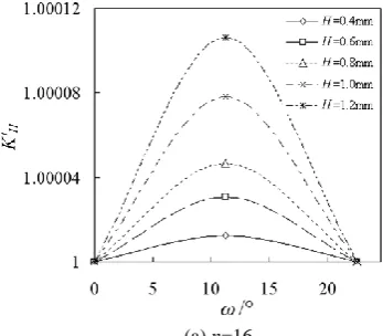
5. 2. Influence of Arc Beam Thickness on Stiffness Homogeneity The trend of homogeneity of radial stiffness with azimuth angle of radial load is shown in Figure 11. The structural parameters are the same values in Table 1. The radial load Fr is 500N. Because of
periodic variation of elastic support stiffness, the change of stiffness homogeneity in one period is plotted in the following figures.
The stiffness homogeneity slightly declines with H. If the groove number is a multiple of 4, the stiffness increases first and then decreases, if not, the stiffness decreases first and then increases with the change of load direction.
0 40 80 120 160 200 240
0.99999 1.00002 1.00005 1.00008
Kn
'
ω
/°n=12
n=16
n=20
Figure 10. Influence of azimuth angle on radial stiffness under different groove number
(a) n=16
(b) n=18
(c) n=20
(d) n=22
Figure 11. Influence of load azimuth angle on radial stiffness under different arc beam thickness
6 CONCLUSIONS
In this paper, all calculations were carried out on the computer with forty Inter(R) Xeon(R) CPU and 192GB of memory. The calculation of analytic formulation spends 0.02s, but FEM needs to more than 30min. The conclusions are:
the relative error of radial stiffness between two methods is less than 10%.
(2) The radial stiffness of groove elastic support increases with the groove number, thickness of arc beam and transition angle, but slightly decreases with the groove gap.
(3) The radial stiffness of groove elastic support changes periodically with the azimuth angle of radial load, but the variation range is small. The greater groove number and smaller thickness of arc beam, the better homogeneity of radial stiffness.
7. ACKNOWLEDGMENTS
This paper has been financially supported by National Natural Science Foundation of China (U1404514), Henan Outstanding Person Foundation in China (144200510020) and the Collaborative Innovation Center of Major Machine Manufacturing in Liaoning, China.
8. REFERENCES
1. Xu, W., Wen, Z., Xu, L., Liu, Y. and Shen, X., "High speed rotating test-bed with flexible, squeeze film damped support", Jixie Gongcheng Xuebao(Chinese Journal of Mechanical
Engineering)(China), Vol. 40, No. 9, (2004), 144-147.
2. Dayi, Z. and Guoxin, M., "Hong jie beijing university of aeronautics and astronautics, beijing 100083, china; rigidity calculation methods for rotor supporting system in gas engine [j]", Tactical Missile Technology, Vol. 2, (2005), 143-150. 3. Ahmadi, S.M., Ghazavi, M. and Sheikhzad, M., "Dynamic
analysis of a rotor supported on ball bearings with waviness and centralizing springs and squeeze film dampers", International
Journal of Engineering-Transactions C: Aspects, Vol. 28, No.
9, (2015), 1351-1360.
4. Kirk, R.G. and Gunter, E.J., "The effect of support flexibility and damping on the dynamic response of a single mass flexible rotor in elastic bearings", (1972).
5. Mahjouri, S., Shabani, R. and Rezazadeh, G., "Vibration analysis of an air compressor based on a hypocycloidal mechanism: An experimental study", International Journal of
Engineering-Transactions B: Applications, Vol. 28, No. 11,
(2015), 1687-1694.
6. Kang, C., Hsu, W., Lee, E. and Shiau, T., "Dynamic analysis of gear-rotor system with viscoelastic supports under residual shaft bow effect", Mechanism and Machine Theory, Vol. 46, No. 3, (2011), 264-275.
7. Ecsedi, I., "Bounds for the torsional rigidity of elastic ring",
Mechanics research Communications, Vol. 26, No. 4, (1999),
445-450.
8. Liu, J. and Chiu, Y., "Analysis of a thin elastic ring under arbitrary loading", Journal of Engineering for Industry, Vol. 96, No. 3, (1974), 870-876.
9. Xingjian, D. and Guangming, W., "Analysis on stiffness of corrugated ring in a rotor-bearing support", Journal of Harbin
Institute of Technology, (1994), 05-13.
10. CAO, L., GAO, D.-p. and JIANG, H.-f., "Investigation on critical speed characteristics of elastic ring sfd-rotor system [j]",
Journal of Propulsion Technology, Vol. 2, (2008), 20-29.
11. Cao, L., Gao, D. and Jiang, H., "Damping mechanism of elastic ring squeeze film damper", Journal of Vibration Engineering, Vol. 6, (2007), 584-589.
12. Zhang, W. and Ding, Q., "Elastic ring deformation and pedestal contact status analysis of elastic ring squeeze film damper",
Journal of Sound and Vibration, Vol. 346, (2015), 314-327.
13. Jie, H., Yin, D. and Dayi, Z., "Dynamic design method of elastic ring squeeze film damper", Journal-Beijing University of
Aeronautics And Astronautics, Vol. 32, No. 6, (2006),
649-655.
14. Zarzour, M.J., "Experimental evaluation of a metal-mesh bearing damper in a high speed test rig", Texas A&M University, (1999),435-442
15. Hongwei, M.Y.L. and Haixiong, Z., "Hong jie school of jet propulsion, beihang university, beijing 100191, china; structural stiffness design and experimental evaluation of elastic ring-metal rubber damper [j]", Acta Aeronautica et Astronautica Sinica, Vol. 6, (2013), 723-730.
16. Zuo, H., Bai, H. and Feng, Y., "The analysis of stiffness for rubbery metallic material based on mesoscopic features",
Materials Sciences and Applications, Vol. 2, No. 06, (2011),
654-660.
17. Wang, D., Zhang, W., Wang, Z. and Zhu, J., "Shape optimization of 3d curved slots and its application to the squirrel-cage elastic support design", Science China Physics,
Mechanics & Astronomy, Vol. 53, No. 10, (2010), 1895-1900.
18. Deng, S.-E., Yan, Y.-C., Wang, Y.-S. and Yang, H.-S., "Vibration analysis of two-piece inner ring angular contact ball bearing with elastic support", Journal of Aerospace Power, Vol. 28, No. 2, (2013), 241-251.
Calculation and Analysis of Groove Elastic Support’s Radial Stiffness
RESEARCH NOTE X. Suna,b, S. Dengb,c, G. Chena, W. Zhangaa School of Mechatronics Engineering, Northwestern Polytechnical University, Xi'an, China b School of Mechatronics Engineering, Henan University of Science and Technology, Luoyang, China c Collaborative Innovation Center of Major Machine Manufacturing in Liaoning, Liaoning, China
P A P E R I N F O
Paper history:
Received 05 January 2017
Received in revised form 21 March 2017 Accepted 21 April 2017