An Under Load Servo Actuator Identification and Comparison
between the Results of Different Methods
M. Maboodi*, M. H. Ashtari Larki** and M. Aliyari Shoorehdeli***
Abstract: This paper addresses the experimental identification of a servo actuator which is used in many industrial applications. Because the system consisted of electrical and mechanical components, the behavior of the system was nonlinear. In addition, the under load behavior of this servo was different. The load torque was considered as the input and a two input-one output model was presented for this servo actuator. Special was given in order to present a simple and applicable model for this servo actuator. For identification of this servo actuator, classic and intelligent methods have been used. ARMAX model as a classic model and MLP and LOLIMOT networks as intelligent models were selected for this purpose and their results have been discussed. The comparisons between these methods show that the intelligent methods have a better accuracy than classical method, but they have more complexity in the implementation. These models can be applied as references for characterizing different designs and future control strategies.
Keywords: ARMAX, Identification, LOLIMOT, MLP, Modeling, Servo actuator.
1 Introduction1
Models of real systems are of fundamental importance in all disciplines. They can be useful in system analysis, i.e., for gaining a better understanding of the system, and make it possible to predict or simulate a system's behavior. In engineering, models are required for designing new processes and for the analyzing an existing process. Advanced techniques for the design of controllers, optimization, supervision and fault detection are also based on the model of processes [1].
Actuators are one of the important parts in the control loop of a system [2, 3]. Servo actuators have many applications in industry, because of specifications like high accuracy and easy application [4, 5].
An exact plant model should produce output responses similar to those of the actual plant. The complexity of most physical plants, however, makes the development of an exact model infeasible. Therefore, in order to design controllers which are reliable and easy to understand, simplified plant models are obtained by
Iranian Journal of Electrical & Electronic Engineering, 2012. Paper first received 15 Oct. 2011 and in revised form 4 July 2012. * The Author is with the Electrical Engineering Group, Islamic Azad University, Hashtgerd Branch, Karaj, Iran.
E-mail: [email protected]
** The Author is with the Department of Electrical Engineering,Iran University of Science and Technology, Tehran, Iran.
E-mail: [email protected]
*** The Author is with the Department of Mechatronics, K.N. Toosi University of Technology, Tehran, Iran.
E-mail: [email protected]
the linearization around operating points and/or reduction in model order [6, 7].
Mathematical models can be developed in two routes (or a combination of them). One route is to split up the system into subsystems whose properties are well understood from previous experience. These subsystems are then joined mathematically and a model of whole system is obtained. Another route to mathematical as well as graphical models is directly based on the open-loop experimentation. Input and output signals from the system are recorded and subjected to data analysis in order to infer a model. When an open-loop experiment is not viable, a close-loop experiment can be done to obtain the plant model [1, 8]. Numerous studies have been reported on model identification using modern tools such as MATLAB System Identification Toolbox and LabVIEW System Identification Toolkit [9, 10].
Because the under load behavior of this servo was different, the load torque was considered as the input and a two input-one output model was presented for this actuator. Thus, inputs of this actuator were input voltage and load torque and its output was a voltage proportional to the shaft position.
For identification of this servo actuator, classic and intelligent methods have been used. ARMAX model as a classic model and MLP and LOLIMOT networks as intelligent models were selected for this purpose and their results have been discussed. The comparison between simulation and experimental results showed the effectiveness of the propose models. These models can
228 be applied designs and f
ARMAX which was u multilayer pe and used publications neural netw (LOLIMOT) conquers str divided into problems, w identifying si model is id obtained. The pape an overview is dedicated identification discussed in and the prop Some conclu
2 The Serv
Today, applications, computers, a The servo ac schematic of
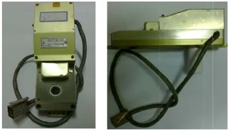
Fig. 1 Photos
Fig. 2 Block d
as references future control X is an impo
sed as a class erceptron (ML
neural netw the MLP is work. The ) approach rategy. A co a number of which are solv imple, e.g., lin dentified, the
er is organized of the servo a d to an o n method. T
Section 4. M posed method usive remarks vo Actuator servo actuat including automobiles, ctuator in this f actuator is de
of the servo act
diagram of the s
I s for charact
strategies. ortant linear
ic model for t LP) is the mo work architec even used as local linea is based on omplex mode f smaller and ved (almost) i near models. A e continuous
d as follows. S actuator under overview of The experim Model parame
d are discuss are stated in S
tors are use toys, hom ships, aircraf
study is show epicted in Fig.
tuator.
servo actuator.
Iranian Journ terizing differ
dynamic mo this purpose. T ost widely kno
cture. In m s a synonym ar model t n a divide-eling problem
thus simpler independently After the discr
model can
Section 2 prese r study. Sectio f the ARM mental setup eter identificat
ed in Section Section 6.
ed in manif me equipm fts, missiles, wn in Fig. 1. T
. 2.
nal of Electrica rent odel The own many for tree and m is sub y by rete be ents on 3 AX is tion n 5. fold ment, etc. The Ge pos sha ran vol 3 ma inp a v wh ma nex rol the to thi and dyn min mo Th wr wh be num Fig
al & Electron This system earbox, Poten
sition sensor i aft, the scale nge of the inpu
lt and +10 vol
System Iden System ident athematical m put-output. Th vector form, as
1 , 1
here
Is the in Is the o
The model o apping from a
xt output The input si le in system id e only possibi
gather inform s servo actua d height were
The ARMA namic mode nimum varian odel and expl he ARMAX m
itten in a com
here
1
1
In above equ estimated.
1 is the nu mber of c coe
g. 3ARMAX: s
nic Engineerin m consists o ntiometer, etc is used for det factor of wh ut voltage of t lt.
ntification Me tification is a models of a he input-outpu
s follow.
1 , 2 , 2 ,
nput to dynam output to dyna
of the dynami a subset of the
.
ignal of the p dentification. ility for influe mation about it ator, a pulse s
used.
3.1 ARM AX model is
l. Some con nce control a
oit the inform model is depic mpact way usin
uation , a is the numb umber of zero efficients.
standard structu
ng, Vol. 8, No. of amplifier, c. The Potent
tecting the def ich is 0.357 v this actuator is
ethods technique tha
dynamical s ut data can be
, … , ,
mic system in i amic system in
ical system ca e past data
process plays Clearly, the i encing the pro ts behavior. Fo signal with di
MAX a widely a ntroller desig are based on mation in the cted in Fig. 3 ng the followin
and are the ber of poles o os of the syst
ure.
White noise di
1
3, Sep. 2012 DC motor, tiometer type flection of the volt/deg. The s between -10
at allows find system using e organized in
(1)
instant k. n instant k.
an be seen as into the
an important nput signal is ocess in order or identifying ifferent width
applied linear gns such as the ARMAX noise model. 3, and can be ng notation
(2)
(3)
parameters to of the system. tem. is the
isturbance , e e e 0 d g n ) s e t s r g h r s X . e ) ) o . e
There a parameters o optimization
One of architecture their proprie propriety en approximate dimension N 4 is showed t The MLP
where
Est We We Nu Nu
In our wo activation fun
3.3 Lo LOLIMO algorithm th orthogonal s linear model that, validity linear model The LOLIMO which the st inner loop in estimated by
Fig. 4 A multi
are some m of ARMAX
[1, 8].
3.2 f the most
is MLP. The ety as univer nsures that is any functio N to an output
the MLP struc P can be writte
. 1
timate output eights from th eights from hi umber of neuro umber of the in
ork we used nctions in the
cal Linear M OT is an i hat partitions splits. In each l (LLM) is ad y functions a s are adapted OT algorithm tructure of the n which the local least sq
ilayer perceptro
methods for model, such
2 MLP common n e main feature rsal approxim s possible to on from an space of dime cture. en as Eq. (4)
1
produce by th he output layer idden layer. on in the hidd nput.
MLP structur hidden layer.
Model Tree (L incremental s the input h iteration a n dded to the m are calculated with the least m consists of an
e model is de parameters o quares.
on network.
estimation h as less squ
neural netw e of the MLP mation [11]. T use a MLP input space ension M. In F
he MLP. r.
den layer.
re with nonlin .
LOLIMOT) tree-construct
space by ax new rule or lo model [1]. To
d and the lo t squares meth n external loop etermined and of the model
of uare
work P is This P to
of Fig.
(4)
near
tion xis-ocal o do
ocal hod. p in d an
are 1.
2.
3.
4.
5.
alg dim
Fig
Short descrip Start with an Construct th input space parameters b Find the wo Calculate th
1, … , loc where M LLM. Check all po The worst optimization linear. Mod the axes in dimensions Find the bes The best am The optimiz the model. T
1. Check for c If the final otherwise re Fig. 5 illust gorithm in t mensional inpu
g. 5Operation o
ption of the al n initial mode he validity fu e portioning by local least orst LLM.
he loss func cal linear mod
. defin
ossible divisio LLM will ns. Each hyp dels will be d n two pieces. are carried ou st division. mong altern zed local linea The number o
onvergence. criteria is me eturn to step 2 trates the ope the first fou
ut space.
of the LOLIMO
gorithm: el.
unctions for t and estimat squares.
tion for each dels. Find the nes the index
ons.
be considere per rectangle divided orthog Divisions in ut.
natives of step ar models, wil of LLM are in
et, then stop t 2.
eration of th ur iterations
OT structure sea
the beginning te the LLM
h of the e worst LLM,
of the worst
ed for further of the local gonally along n every of
p 3 is chosen. ll be added to ncremented to
the algorithm,
e LOLIMOT for a
two-arch algorithm.
g M
, t
r l g
. o o
,
T
230 4. The Exp
Because mechanical c nonlinear. T sources; how external load
Hence, in bed, which needed. To p electrical mo of the torque A-30kg) was to the base pl of the motor necessary be coupling wa electrical mo 4 The serv was develop actuator and data from th test. The soft work shop software co thorough an analog outp performance of Volt-Tim command. In additio software spe must be app actuator can
5. Model Pa The iden with two inp shown in Fig
Fig. 6 Input/ou
erimental Te 4.1 T the system component, th These nonlin wever, the im d applied to th
n order to sim can apply e produce a sui otor was used e, during the t s used. One en
late and anoth r with a fixe etween the end
as used for otor to the shaf
4.2 Data Acq vo link monit
ped for the d it was used he real-time H ftware is based
with the sam ommunicates
analog input c put card (A of the servo a me curve, r
on to plotting cified the amp plied to the support the ex
arameter Ide ntification of
uts , g. 6.
utput model of
I est Rig Test Bed consists of he behavior nearities aris mportant part he shaft.
mulate a real xternal load itable torque i d and to contr est, the S type nd of the load her end, was li ed arm. A go ds of the shaf
connecting t ft of the servo
quisition Softw oring and dia
online moni here to acqu HIL (Hardwa d on simulink mpling rate o
with the card (Advante Advantech P
actuator is illu esulting from
the system res plitude of ext
shaft of the xternal load u
entification this system,
and one
the servo actua
Iranian Journ f electrical of the system e from sev t of that is
situation, a to the shaft in a fix level, rol the amplit e load cell (ST d cell was join
inked to the sh ood alignmen ft; hence, flexi the shaft of o actuator.
ware
agnosis softw itoring of se uire experimen
are in the Lo k® and Real-t
of 100 Hz. T servo actua ech 818 HG) PCL 726). T
ustrated by nat m a PE in
sponse curve, ternal load wh
e actuator. T up to 15 N.m.
was conside output
ator.
nal of Electrica and m is eral the test , is , an tude TC-nted haft nt is ible the ware ervo ntal oop) ime The ator and The ture nput the hich This ered , as sys we inp wh wh ma of the est sys me thr and AR dif tha see Ta Fig ope
al & Electron A special cas stem where ell-established put/output beh
here
hich is tran athematical re
the researche e second ord timate the act stem can be ethods with th
Using MAT ree different m
d third orde RMAX2121). fferent models at the perform ems that secon
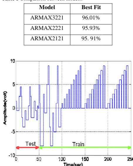
ble 1Comparis
M
ARM
ARM
ARM
g. 7 Input dat erating condit
nic Engineerin se is a
single-0 or d model havior like:
nsfer functio epresentation o ers’ knowledg
der ARMAX tuator dynami e found usi e test data, wh TLAB System models were rs (ARMAX
Table 1 sh s. Based on th mance don’t nd order is eno
son between mo
Model
MAX3221
MAX2221
MAX2121
ta for excitin tion.
ng, Vol. 8, No. -input single-o
. The SI structures
0
on of the of servo actu e about the se X model was
ic. Moreover, ing system hich is shown m Identificati obtained wit X3221, ARMA
hows the res he Best Fit cr change very ough for our p
odels.
Best Fit
96.01%
95.93%
95. 91%
ng the system
3, Sep. 2012 output (SISO) ISO model is having an (5) (6) system, i.e. ator. Because ervo actuator, s selected to , order of the identification n in Fig. 7.
ion Toolbox, th the second AX2221 and sult of three riteria, we see much. So, it purpose.
m in different ) s n ) ) . e , o e n , d d e e t t
5.1 Linear SISO Model
In this part, a linear model is identified using measurement and . The method used for identification was described in Section III. To identify a second order SISO linear model, a different torque was applied to the shaft of actuator.
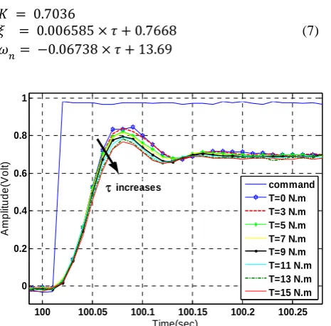
The actuator response in different operating conditions is depicted in Fig. 8. By increasing the external load to the shaft, overshoot decreased; however the DC gain of the system was almost fixed.
While Real-Time Workshop was used for experiments and data acquisition, the identification and modeling procedures were performed on MATLAB. The models obtained in the transfer function form, are represented in Table 2.
5.2 Linear MISO Model
Here we use a result of pervious section to extract a second order MISO model, that is depend on amplitude of the Torque. All transfer function demonstrated in Table 2, can be represented with three parameters: DC gain
Damping ratio
Undamped natural frequency
This parameters for each transfer function of Table 2, is tabulated in Table 3. It can be seen, by increasing the amplitude of external load to the shaft of actuator, DC gain is nearly fixed, was increased and was decreased. Using classical curve fitting, the relationships between the , , and external load was found to correspond to the following functions.
0.7036
0.006585 0.7668 (7)
0.06738 13.69
Fig. 8 Actuator response in different torques.
Table 2Model of the system in different Torque.
Torque (N.m) Transfer function
0 0.8288 162.7
21.70 191.5
3 G 0.6966 181.4
20.77 179.6
5 G 0.6954 179.6
21.05 177.4
9 G 0.7596 157.3
21.38 169.8
11 G 0.7516 154.7
21.68 165.3
15 G 0.7414 155.8
22.35 164.4
The transfer function ⁄ derived with standard transfer function model of second order system and the data is shown in Table 3.
.
2 (8)
This is new representation and new transfer function model of the servo actuator. The coefficient in this model is depending on the external load.
The model was simulated and the results were compared with the data obtained from experiments. The correspondence between the measured and calculated output voltage was considered for verification.
In Fig. 9, the graphs show the experimentally obtained curves (in Torque = 7 N.m) with simulated ones. It can be seen that the results corroborate well with the experimental data.
Table 3 Models of the system in different Torque.
Torque (N.m)
0 0.7040 0.7839 13.84
3 0.7034 0.7747 13.40
5 0.7040 0.7903 13.32
9 0.7038 0.8204 13.03
11 0.7035 0.8432 12.85
15 0.7035 0.8717 12.82
100 100.05 100.1 100.15 100.2 100.25
0 0.2 0.4 0.6 0.8 1
Time(sec)
Ampl
it
ud
e(
Vol
t)
command T=0 N.m T=3 N.m T=5 N.m T=7 N.m T=9 N.m T=11 N.m T=13 N.m T=15 N.m
τincreases
232 Iranian Journal of Electrical & Electronic Engineering, Vol. 8, No. 3, Sep. 2012 Fig. 9Experimental Values vs. Model Estimated Values
5.3 Intelligent Modeling
The multilayer perceptron (MLP) and Local Linear Model Tree (LOLIMOT) are the most widely known and used neural network architecture. Now, we will obtain the model of the system using MLP and LOLIMOT method. We used two neurons in hidden layer of network. We used Levenberg Marqurdt and gradient descend method for the training the MLP and LOLIMOT network, respectively.
In this modeling, to estimate the output voltage of actuator , we use four signal as a input of the network. These signal are input voltage , amplitude of the tourqe τ , output voltage in two previous sample 1 and 2 .
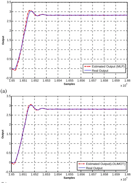
With applying this method to the input data, the network output, is represented in Fig. 10.
Note, the model obtained using MLP method is the same obtained using LOLIMOT method and both methods predict system behaviour, as well.
6. Conclusions
A two input-one output model was developed for an under-load servo actuator. The load torque was considered as the input. The unknown parameters (ARMAX parameters) were identified from experimental data. The system was excited using pulses with different height and width. The proposed method provided a linear MISO model for the actuator servo. The transfer function ⁄ was derived with standard transfer function model of the second order system. In this model the DC gain was nearly fixed. Damping ratio and undamped natural frequency were linear functions of the external load to the shaft.
Acknowledgment
The authors would like to acknowledge the funding support of the Islamic Azad University, Hashtgerd Branch. This paper is a partial result of the project "An Underload Servo Actuator Identification and Comparison between the Result of Different Methods".
(a)
(b)
Fig. 10Model estimated based on (a) MLP and (b) LOLIMOT networks.
References
[1] Nelles O, “Nonlinear System Identification: From Classical Approaches to Neural Network and Fuzzy Models”, Springer, Berlin, 2001.
[2] Maboodi M., Ashtari Larki M. H., Aliyari Shoorehdeli M. and Bolandi H., “An Underload Servo Actuator Identification”, 18th IFAC world Congress, Milano, Italy, 2011.
[3] Lacy L. L., Bernstein D. S., “Identification of an Electromagnetic Actuator”, 41th Int. IEEE Conf. On Decision and Control, Las Vegas, Nevada USA, 2002.
[4] Schaab J., Muenchhof M., Vogt M. and Isermann R., “Identification of a Hydraulic Servo-Axis Using Support Vector Machines”, 16th IFAC World Congress, Prague, Czech Republic, 2005. [5] Modabberifar M., Hojjat Y., Abdullah A. and
Dadkhah M., “Identification of Three Phase Panel Type Electrostatic Actuator”, 15th International Conference on Mechatronics and Machine Vision in Practice, pp. 447-454, 2008.
[6] Laghrouche S., Ahmed F. S., El Baghdouri M., Wack M., Gaber J. and Becherif M., “Modelling and Identification of a Mechatronics Exhaust Gas Recirculation Actuator of an Internal Combustion
134.5 135 135.5 136 136.5 137 137.5 138 138.5
-1 0 1 2 3 4 5 6 7 8
Linear Simulation Results
Time (sec)
A
m
pl
it
ud
e
Real Response Estimated Response
1.65 1.651 1.652 1.653 1.654 1.655 1.656 1.657 1.658 1.659 1.66
x 104
-0.5 0 0.5 1 1.5 2 2.5 3 3.5
Samples
Ou
tp
u
t
Estimated Output (MLP) Real Output
1.65 1.651 1.652 1.653 1.654 1.655 1.656 1.657 1.658 1.659 1.66
x 104
-0.5 0 0.5 1 1.5 2 2.5 3 3.5
Samples
Ou
tp
u
t
Estimated Output(LOLIMOT) Real Output
Engine 2242-2 [7] Koveo
Identif Contro Contro [8] Ljung
user”, Englew [9] Jelavic
“Ident Contro Electro 2006. [10] Shao J
Identif Positio Human 210-21 [11] Mühle
percep networ Augus
Assessment (C and Optimizat
e”, American 2247, 2010. os Y. and
fication of R ol Applicatio ol, (ISIC), pp.
L, “System I (2nd Edi wood Cliffs, N c M., Per
ification of oller Design”
onics and Mo J., Wang Z., fication and on Servo Syst
n-Machine Sy 13, 2009. enbein h., “ ptron network
rks”, Parallel st 1990, pp. 24
Mohse
Iran, in from Techno M.Sc Sharif Tehran Ph.D. Univer interest CPA), Predictiv tion.
n Control C Tzes A, “ Resonance F ons, (CCA)
560-565, 200 Identification: ition), Pren NJ, 1999. ric N. and
Wind Turb ”, 12th Int. C
otion Control, Lin J. and H
Control E tem”, Int. Co System and C
“Limitations s-steps toward l Computing, 49–260, 2003.
en Maboodi w n 1984. He r
K.N. Toosi ology, Tehran,
in Electrical University n, Iran in 2009.
candidate sity of Techno ts include Con ve Control, Sy
Conference, “Modelling Fluid Actuato
& Intellig 09.
: Theory for ntice-Hall, I
d Petrovic bine Model Conf. On Pow
, pp. 1608-16 Han G., “Mo Electro-Hydrau onf. on Intellig
Cybernetics, of multi-la ds genetic neu
Vol. 14, Issue .
was born in Ka received his B University Iran in 2007 Engineering f
of Technolo . He is current in K.N. T ology. His resea
ntrol Performa stem Identifica
pp.
and or”, gent the Inc.,
I., for wer 613,
odel ulic gent pp.
ayer ural e 3,
araj, B.Sc. of and from ogy, tly a oosi arch ance ation
doc Bas inte orb
inc Net and
ctoral dissertati sed on Optimi erests include bit determinatio
ludes Mechatr tworks, Fuzzy d Predication, P
M. H. A
Khuzestan the B.Sc Electrical Nasir Too Tehran, I respectivel
candidate
Departmen and Tech ion concerned ization Techniq flight control, n and orbit con
Mahdi A
his B.Sc., electrical Nasir Too Tehran, Ir respectivel professor Mechatron Electrical University ronics System systems, Nero Pattern Recogni
Ashtari Larki
n, Iran, in 1984 . and M.Sc.
Engineering si University o Iran, in 200 ly. He is curr
in Electrical nt, Iran Univers hnology, Tehra Satellite orbit que. Ashtari's optimal contro ntrol.
liyari Shooreh
M.Sc. and Ph engineering si University o ran, in 2001, 2 ly. He is curren at Dep nics Control,
Engineerin y. His rese ms, Fault Diag
o-Fuzzy control ition and Swarm
was born in 4. He received . degrees in from Khajeh of Technology, 6 and 2008, rently a Ph.D l Engineering sity of Science an, Iran. His t determination main research ol and satellite
hdeli received h.D. degrees in from Khajeh of Technology, 2003 and 2008 ntly an assistant partment of Faculty of ng K.N.T.U earch interest gnosis, Neural l, Identification m Intelligence.
n d n h , , D g e s n h e
d n h , 8 t f f U t l n