Calculation of Stray Capacitances of MCG Coil include One
Turn, Single-Layer and Conductor Wire Filaments in
Rectangular form
M. E. Mosleh* and M. R. Besmi**
Abstract: This paper presents a new method called vespiary regular hexagonal (VRH)
model in order to calculate parasitic capacitance between conductor wire filaments of one turn of coil (OTC) and between conductor wire filaments and liner and also total capacitance of one turn of the helix magneto flux cumulative generator (MCG) coil include single-layer conductor wire filaments in form of rectangular cross-section. In this paper, wire filaments of the coil are separated into many very small similar elementary cells. In this structure, an equilateral lozenge-shape basic cell (ELBC) with two trapezium-shape regions is considered between two adjacent conductor wire filaments in one turn of the generator coil. This method applies to calculate stray capacitance of one turn of the coil with multi conductor wire filaments (CWFs).
Keywords: Magneto Flux Cumulative Generator, Single-layer, Stray Capacitance,
Vespiary Model.
1 Introduction1
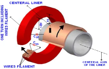
In the design of a helix magneto flux cumulative generator (MCG) (see Fig. 1.), in order to well and correct performance of the generator, we need to obtain a geometrical model with sufficient accuracy and appropriate characteristics of geometrical components. An appropriate geometrical model will increase the accuracy of generator parameters calculation and hence raises effectiveness and efficiency of the generator. In the past studies the MCG coil was simulated only by resistance and inductance [1]-[2]. In our studies we have never seen the effects of stray capacitance in the MCG modeling. In this paper, for the first time, the effects of stray capacitance in the MCG are discussed and analyzed. However in the past, high-frequency behavior magnetic components are discussed in various papers and literatures. But the problems related only to the stray self-capacitances and H.F. resistance of a single layer and multi layers inductors, coils, circuits of electronic and electric in very small dimensions [3]-[6]. Also behavior of a transformer and determination and calculation of the stray capacitances in the
Iranian Journal of Electrical & Electronic Engineering, 2011. Paper first received 19 Aug. 2010 and in revised form 15 Nov. 2010.
* The Author is with the Department of Electrical Eng., Shahed University, Tehran, Iran.
E-mail: [email protected].
** The Author is with the Department of Electrical Eng., Shahed University, Tehran, Iran.
E-mail: [email protected].
frequencies and high-voltages are discussed and analyzed in [7]-[11].
Effects of stray and eddy currents in transformer are described in [12]. The aspects related to the parasitic ac winding resistances and core losses for single and multiple-layer inductors, RF circuits and EMI filters, electromagnetic field theory are discussed and analyzed in [13]-[18]. The most recent important researches are presented about high frequency magnetic components in [19]. But in the literatures review we have not seen any paper about stray capacitance modeling for the MCG.
The aim of this paper is to present a model to calculate stray capacitance of MCG coil for one turn with single layer and rectangular cross section.
Parasitic capacitance of the coil has significant effect on generator function. The purpose of this paper is to present a new method for predicting and calculating stray capacitance of OTC with single-layer, k-conductor wire filaments (k-CWFs) (k=number of the conductor wire filaments) in form (arrangement) of rectangular cross-section (Fig. 2).
The proposed method in this paper is a function of various parameters, turn geometrical coordinates and the number of CWFs in OTC. By using the presented method, we can calculate stray capacitance of OTC.
Further in MCG, effects of electrical field will be too much, because of two reasons; the voltage increase in each turn during explosion progress and decrease of the number of coil turns.
It should be noted that electrical field produced by operation of the MCG process and the lines of electrical field produced by it, between turns of the coil and also between turn and cylindrical liner placed at the coil center, make turn-turn
( )
C and turn-liner tt( )
C tlcapacitances.
Analysis presented in this paper applies for coils include single-layer with filamentary conductors in form of rectangular cross-section. Frequency increase in the coil of MCG makes skin effect and proximity effects which finally causes increase of resistance of the coil turns. Also, because of capacitance in the system, resultant impedance of the generator will increase.
Therefore, to calculate total capacitance of one turn of coil (OTC), we need to calculate:
• Stray capacitance between conductor wire filaments in one turn, wire filament - wire filament capasitance
( )
Css .• Stray capacitance between wire filaments of one turn coil and liner, wire filament – liner capasitance
( )
C . sl2 Algorithm and Method of Capacitance
Algorithm used in this paper is as follows:
(a) Considering an overall model for equivalent circuit of OTC.
(b) Calculation of filament-filament capacitance
( )
Cssand filament-liner
( )
C capacitance. sl(c) Calculation of filament-liner capacitance
( )
C . sl(d) Calculation of total parasitic capacitance C(k) for OTC.
(e) Simulation of total parasitic capacitance C(k) for OTC.
(f) Total stray capacitance of OTC of the MCG can be modeled by a lumped capacitance connected between the terminals of OTC, as shown in Fig. 3, [5].
Fig. 1 Helix generator (MCG) with explosive detonator.
(a)before explosion, (b) during explosion.
Fig. 2 View of OTC of the MCG includes single-layer
k-CWFs in form of rectangular cross-section.
(a)
(b)
Fig. 3 Equivalent circuit of OTC of the MCG. a) Equivalent
circuit of OTC of the MCG b) Simplified equivalent RLC circuit of the generator OTC
2.1 Assumptions for OTC Including k-CWFs
In order to draw details of Fig. 3, we suppose following assumptions.
A) We neglect the capacitance between non-adjacent wire filament turns of OTC.
B) Air gap between all CWFs in a turn of the generator coil and central cylindrical liner are equal and considered to be Z. Because air gap between CWFs and central cylindrical liner is much bigger than the diameter of the cross-section of one turn of the coil, so it could be neglected by a slight error. See Fig. 5.
C) We neglect capacitance leakage effects between edges of two CWFs and also between edges of CWF and central cylindrical liner of the MCG.
Figure 4 shows capacitances produced between CWFs of only one turn with liner, which includes the following:
1- Filament-filament capacitance
( )
Css betweennon-adjacent wire filaments in a turn of the coil. 2- Filament-filament capacitance
( )
Css betweenadjacent wire filaments in a turn of the coil. 3- Filament-liner capacitance
( )
C . slFigure 5 shows the cross-section of OTC with one layer of CWFs which has been wounded uniformly. It is clearly seen that, in order to calculate the capacitance between two CWFs of OTC, first we consider a regular hexagon with perfectly equal angles, 2π/ 3 radian and perfectly equal sides that each side be equal to y in round cross-section of each CWF so that the center of this hexagon overlaps with the center of the round cross-section of each CWF.
Arcs opposite to sides of this hexagon are perfectly equal because of geometric equality of sides. Now, consider an equilateral lozenge-shaped basic cell (ELBC) composed of two trapezoid shape regions (regions 1 and 2 of Fig. 7). Extension of the sides of this equilateral lozenge will pass from two adjacent apex of hexagon and will be tangent to external surfaces of adjacent CWFs.
Fig. 4 View of total stray capacitance of one turn includes
several wire filaments of the MCG coil in non real scale.
Fig. 5 Rectangular cross-section of one turn of the MCG coil
include single-layer CWFs in non real scale.
Here, the hexagon region which is similar to a regular hexagon network and also similar to vespiary is called vespiary regular hexagonal (VHR) region.
Figures 6 and 7 show lozenge basic cell abcd related to filament-filament capacitance
( )
Css . By looking atFigs. 5 and 6, we can find geometric symmetry of CWFs of OTC. By considering this geometric symmetry of CWFs, fraction of electric field lines which exit from a CWF, is completely surrounded by two adjacent CWFs around this CWF. By considering the geometric symmetry of the coil, electric field lines should be divided equally among two adjacent CWFs.
If we consider two close adjacent CWFs in one turn, then dc elementary capacitance between two elementary surfaces of these two CWFs with area of dS which are opposite to each other will be:
ds dC
g( )β
= (1)
0* r
ε ε ε= (2)
where, εr is relative permittivity and
12 0 8.85*10
ε = − is vacuum permittivity and g(β) is length of electric field lines between two elementary conductor surfaces which are opposite to each other.
Fig. 6 An abcd equilateral lozenge-shape basic cell for calculating filament-filament capacitance. a) Vespiary regular hexagon (VHR) region b) abcd basic cell.
In this paper, "g" is a function of two CWFs elementary surface positions of OTC with angle "g" and is not constant. Thus, position of each elementary surface for each circular CWF in a turn of the generator coil could be stated by angle "g" coordinates (Fig. 7).
3 Filament-Filament Capacitance Between Two CWFs in OTC
3.1 Structure of ELBC of Vespiary Model
Figure 7 shows an equilateral lozenge basic cell 'abcd' which forms filament-filament capacitance
( )
Css .It was clearly seen that the geometric structure of the basic cell is the same for two adjacent CWFs of the same layer and two adjacent CWFs of different layers. Thus, internal region of the cross-section of one turn of coil could be divided into similar basic cells and only adjacent cells to central cylindrical liner will be different from filament- filament cell.
(a)
(b)
Fig. 7 View of path g(β) of electrical field lines E under angel
β between two adjacent CWFs in OTC of the generator. a) View of g(β) path of electrical field lines under β angle b) Two trapezium-shape regions 1 and 2 in ELBC
By an approximation and simple preliminary assumption, we can suppose all basic cells to be similar and identical. These basic cells include a region of the periphery of the CWFs, which correspond to angle of
/ 3
π radian. (See Fig. 6).
Therefore, in order to obtain filament-filament capacitance of one turn of coil, we should integrate (1) under angle of / 3π radian. This expression can be accepted for CWFs which are surrounded by two other adjacent CWFs, because of geometric symmetry as shown in Figs. 5, 6 and 7.
By approximation, we can neglect the edge capacitance and fringing effects. Therefore, we can use the same angle of / 3π radian for CWFs which are not perfectly surrounded.
For equilateral lozenge-shape basic cell (ELBC) shown in Fig. 6, three different regions are crossed by electric field lines that they are:
1- Insulating coating region of the first CWF. 2- Insulating coating region of the second CWF. 3- Air gap region between two above CWFs in OTC which are adjacent.
Therefore, elementary capacitance of dC between adjacent CWFs in OTC of the generator is equivalent to series combination of three elementary capacitors in three above regions. In other words, first capacitor is related to insulating coating of the first CWF, second capacitor is related to air gap between two adjacent CWFs and third capacitor is related to insulating coating of the second CWF. Surfaces of CWFs are considered co-potential by a relatively good approximation.
As you can see, the direction of electric field lines between two adjacent CWFs in OTC is in radial form. By a good approximation, we can consider the shortest possible path which is parallel to the line connecting two centers of two adjacent circular CWFs, as the path of the electric field lines under consideration. This approximation applies for small amounts of β angle which has a main role in filament-filament capacitance
( )
Css . For big amounts of β, error of this approximationwill increase, so that big amounts of β lead to increase the capacitance value in comparison with the actual value. Anyway, the filament-filament capacitance of surfaces will decrease when β amounts increase. Also by increasing of β amounts, error amount produced in capacitance will be negligible.
3.2 Capacitance of Insulating Coating ( )Cic Between Two Adjacent CWFs in OTC of the Generator
In this section, a method is presented to calculate capacitance of insulating coating in one turn of the MCG coil. Fig. 8 shows a cylindrical elementary surface placed between the surface of CWFs and the surface of insulating coating.
Elementary capacitance related to this cylindrical insulating will be:
Fig. 8 View of cylindrical elementary cross-section placed in
insulating coating in non-real scale.
r *d *dh
ds ic
dCic g( ) 0* r* dr
ic β ε β ε ε
= = (3)
Integration of this equation for the range of radius (r) from the radius of CWF without insulating coating
( )
r to outer radius of CWF with insulating coating w( )
rw ic− and for h (turn length of CWF) from zero to turn length of CWF( )
L , shows the capacitance of tsinsulating coating limited to elementary angle of dβ as: ts w ic
w
l r
0 r
r ic dCic 0* r*d * dh
dr ic
ε ε β −
=
∫ ∫
(4)So we have:
lts
dCic 0* r* d
rw ic
ln
rw
ε ε β
=
⎛ ⎞
−
⎜ ⎟
⎜ ⎟
⎝ ⎠
(5)
Furthermore since two insulating coating of two CWFs in one turn of the coil are combined in series form, so insulating coating elementary capacitance of a basic cell of two adjacent CWFs with β angle will be:
ic ss ic ic ic
1 1 1 2
dC − dC dC dC
= + = (6)
Therefore elementary capacitance of insulating coating of a basic cell is
lts
dCic ss 0* r* d
rw ic
2*ln
rw
ε ε β
=
→ ⎛ ⎞
−
⎜ ⎟
⎜ ⎟
⎝ ⎠
(7)
As a result, by integration of (7) on β, capacitance of insulating coating of two adjacent CWFs in OTC of the generator is obtained by:
l ts
Cic ss( ) 0* r*
r w ic 2*ln
r w
β =ε ε β
→ ⎛ ⎞
−
⎜ ⎟
⎜ ⎟
⎝ ⎠
(8)
3.3 Air Gap Capacitance
( )
Cag Between TwoAdjacent CWFs in OTC of the Generator
Considering Figs. 6 and 7, angle ofβ is:
w ic
g( ) cos( ) 1
D
β β
−
= − (9)
Therefore the length of the paths of the electric field which is a function of β angle will be:
w ic
g( ) Dβ = − *(1 cos( ))− β (10)
The area of elementary surface of the CWF which has insulating coating and is in form of an elementary ring of length(l )ts (turn length of the CWF) will be:
ts w ic
1
ds *l *D d
2 − β
= (11)
Capacitance between two adjacent CWFs relation to air gap in one turn will be:
ds
dC *
ag =ε0 g( )β (12)
Total capacitance of dCag ss→ related to air gap between two adjacent CWFs will be:
l * Dts w ic lts
dCag ss( ) 0* d 0* d
2* g( ) 2* (1 cos( ))
β ε β ε β
β β
−
= =
→ − (13)
Therefore, we can obtain air gap capacitance
(
Cag ss→)
between two adjacent CWFs in OTC of thegenerator by integration of (14) in β π= / 6. Thus we will have:
6 0
1 Cag ss( ) * 0* lts
2
1 d 1 cos( ) π
β β
β ε β
β =
=
=
→
∫
− (14)4 Calculation of Filament-Filament Capacitance
ss
C Between Two Adjacent CWFs in OTC of the MCG
Since capacitances of two regions 1 and 2 between
two adjacent CWFs will be combined in parallel form, so we have:
dC ( ) dCss β = ss1( ) dCβ + ss2( ) 2*dCβ = ss1( )β (15) where, dC ( )ss1 β is total capacitance of region 1 and
ss2
dC ( )β is total capacitance of region 2 between two CWFs that by considering the geometrical symmetry of two regions 1 and 2 in Fig. 7, the capacitances of these two regions are equal.
Since elementary capacitance of insulating coating and elementary capacitance of air gap between two adjacent CWFs of each two trapezoid shaped regions 1 or 2 are combined in series form, so by considering (15), total capacitance between two adjacent CWFs will be:
dC *dC ( )
ic ss ag ss dC ( ) 2*dC ( )ss ss1
dC 2dC ( )
ic ss ag ss
β
β β
β
→ →
= =
+
→ →
(16)
Therefore by considering the effect of insulating coating, total filament-filament capacitances
( )
Css of twoadjacent CWFs in OTC of the MCG is: *l
0 ts
C ( )ss d
D
1 w ic 1 cos( ) 2*ln
r D
w
ε
β β
β ε
=
− −
− + ⎛⎜ ⎞⎟
⎜ ⎟
⎝ ⎠
(17)
By integration of (17) and by considering range of angle (β) from zero to π/ 6 and by replacing parameters, value of capacitance
( )
Css between twoadjacent CWFs will be:
Arc tan tan * K2
24
Css 0* r*l *ts
K3
π
ε ε
⎛ ⎛ ⎞⎞ ⎜ ⎜⎝ ⎟⎠⎟
⎝ ⎠
= (18)
where 1 w ic w
D K
D
−
= , K2 * ln(K1)
(
)
1 1r
ε −
= + and
(
)
2K3 *ln(K1) ln(K1)
r
ε
= + .
5 Filament-Liner Capacitance Between one CWF in OTC and Liner
To calculate filament-liner capacitance
( )
C , first slwe use (5) to calculate the capacitance of insulating coating which is placed between CWF and liner. Here we remind that we have only one insulating coating for calculating filament-liner capacitance.
So we have:
* *l
0 r ts
dC dC d
ic sl ic r
w ic ln
r w
ε ε
α
= =
→ ⎛ ⎞
−
⎜ ⎟
⎜ ⎟
⎝ ⎠
(19)
Besides, path length of electric field lines in air gap between CWF and imaginary ψ line which on average passes from the middle of coil turn, is equal to Z. Also,
the basic cell of filament-liner capacitance is bigger and wider than the basic cell of filament-filament capacitance and a part of the perimeter of the CWF which by an approximation and simplified assumptions, conforms to 2π/3 radian, will include the basic cell of filament-liner (Fig. 7). Considering Figs. 6 and 7, the value of angle α is:
2g ( )
cos( ) 1
D
w ic
α α = −
−
(20)
Thus, path length of electric field that is function of angleα will be:
D *(1 cos( ))
w ic g( )
2 α
α = − − (21)
The area of elementary surface of the CWF which has insulating coating and is in form of an elementary ring of length lts (turn length of the CWF) will be:
1
ds *l * Dts w icd
2 α
= − (22)
Also, capacitance between CWF and central cylindrical liner related to air gap is:
ds dCag sl 0*
g( ) Z
ε α =
→ +
(23)
where dCag sl→ is total capacitance related to region 3 of air gap between CWF and central cylindrical liner. So, by considering above explanations and equations (21), (22), and (23), the air gap capacitance of filament-liner of region 3 is:
* l * D 0 ts w ic
dCag sl( ) d
2(g( ) Z)
ε
α α
α − =
→ +
(24)
Thus to replace (21) in (24), air gap capacitance between wire filament and liner in regain (3) will be:
* l * D 0 ts w ic
dCag sl( ) d
D * (1 cos( )) 2Z w ic
ε
α α
α − =
→ − +
−
(25)
Considering Figs. 6 and 7 and considering that α is between zero to π/ 3 and also by integration of (25), value of the air gap capacitance between liner and CWF of region (3) that place in one turn will be:
(D Z)
w ic Arc tan
3 Z
Cag sl( ) 0*l *D *
ts w ic D Z
w ic Z* 1
Z
α ε
+ −
+ =
→ − +
− +
⎡ ⎤
⎢ ⎥
⎢ ⎥
⎣ ⎦ (26)
Since capacitance between CWF and central cylindrical liner of two regions 3 and 4 are combined in parallel form, we have:
C ( )sl α =dCsl3( ) dCα + sl4( )α =2 * dCsl3( )α (27) where dCsl3( )α is total capacitance of region (3) and
dCsl4( )α is total capacitance of region (4) between CWF and central cylindrical liner and considering the geometrical symmetry of two regions 3 and 4 in Fig. 7,
capacitances of these two regions are equal.
Considering the series combination of air gap elementary capacitance and insulating coating of trapezoid shaped region 3 or 4, then the total equivalent capacitance between CWF in OTC and central cylindrical liner with considering (27) is:
dC * dC
ag sl ic sl dC ( )sl 2 * dCsl3( )
dC 2dC
ic sl ag sl
α = α = → →
+
→ →
(28)
Therefore we have: 2 l * D
2 ts w ic
dC ( )sl 2 * * d
0 r K4 (K5 *[ l ]) 0 r ts
α ε ε α
ε ε− =
+ (29)
where K4 (2 * D *l ) *ln(K1)
0 w ic ts
ε
= − and
K5 2Z D (1 cos( ))
w ic α
= + − − .
So C ( )sl α will be:
K9 1
Arc tan *
K6 K7 K8 3 C ( ) K10*sl
K6 K7 K8
α = + +
+ +
⎡ ⎤
⎢ ⎥
⎣ ⎦ (30)
where K6 2* Z(D Z)
r w ic
ε
= +
− ,
K7 D * (D 2Z) ln(K1) w ic εr w ic
= +
− − ,
2 2 K8 D * ln (K1)
w ic
= − ,
K9 (D Z) (D * ln(K1))
r w ic w ic
ε
= + +
− − and
K10 2 * * * l * D 0 r ts w ic
ε ε
=
− .
6 Total Stray Capacitance of OTC of the MCG
In order to obtain total stray capacitance of one single-layer turn of the MCG coil in form of rectangular cross-section, as it is shown in Fig. 9, first by using filament-filament capacitance
( )
Css and filament-linercapacitance
( )
C corresponding to Fig.10, we calculate sltotal stray capacitance C(k), single-layer adjacent k-CWFs of the MCG coil.
A network composed of lumped capacitors according to Fig. 10 can describe total stray capacitance (filament-filament plus filament-liner). So equivalent circuit can be modeled by a total stray capacitor network C(k) [5].
Fig. 11 shows a network of lumped capacitors for one turn that has single-layer k conductor wire filaments (k-CWFs) in form of rectangular cross-section and is wounded around the central cylindrical conductor liner, that for one turn, capacitor network of Fig. 11 should be solved.
Central cylindrical conductor liner can be considered as a node that filament-liner capacitance
( )
C is slconnected to this node.
Fig. 9 One turn of the MCG coil includes single-layer
k-CWFs in form of rectangular cross-section with cylindrical liner placed in center of the generator coil.
For OTC of the generator that is composed of many CWFs in itself, first we consider two adjacent wire filaments among wire filaments in one turn of the generator coil for these two filaments (k=2), capacitance of network consists of capacitance
( )
Css between twowire filaments 1 and 2 that is parallel with the series combination of the filament-liner capacitances (C
s(1)l) and (C
s(2)l), which Cs(1)l=Cs(2)l=Csl, where (Cs(1)l) and (C
s(2)l) are capacitance between wire filaments 1 and 2 with central cylindrical liner of the generator respectively.
So, equivalent capacitance of these two adjacent wire filaments is:
Fig. 10 Geometrical space of one turn include single-layer
k-CWFs and cylindrical liner placed at center of the coil turn and filament-filament parasitic capacitance (Css) and
filament-liner parasitic capacitance (Csl) in non-real scale.
Fig. 11 Lump capacitors of one turn include single-layer
k-CWFs of the MCG coil in non-real scale.
C sl C(k 2) C(1, 2) C
tt 2
= = = + (31)
For more number of wire filaments, first we consider three adjacent wire filaments of the MCG coil. Equivalent capacitance of this capacitor network with three wire filaments (k=3) can be obtained by splitting capacitance (C
s(2)l) into two halves and applying the
/
Δ Υ transformations (Fig. 12). So, we will have:
C C
ss sl C(k 3) C(1, 2, 3)
2 2
= = = + (32)
In order to obtain total capacitance of four wire filaments in one turn, we can consider one more wire filament at the side of three wire filaments. So, total capacitance is equal to capacitance of previous arrangement (i.e. two wire filaments), which is in series form with filament-filament capacitance and parallel to the series combination of filament-liner capacitance. Therefore, for k=4, we will have:
C * C(2) C
ss sl
C(k 4) C(1, 2, 3, 4)
C 2 * C(2) 2 ss
= = = +
+ (33)
In order to obtain the total capacitance of k-CWFs, we can add one wire filament to previous wire filaments in each time.
Therefore, total stray capacitance of one turn of the MCG coil with any number of wire filaments can be calculated by mentioned method.
So for OTC of the MCG composed of single-layer k-CWFs, we have:
C * C(k 2) C
ss sl
C(k)
C 2 * C(k 2) 2 ss
=
= +
+ = (34)
where, C(k-2) is stray capacitance of (k-2) wire filaments of OTC of the MCG composed of k-CWFs and k is the total number of wire filaments existing in OTC of the generator.
Two layers k-CWFs turn is affected by higher stray capacitance than single-layer turn. Also it is affected by higher resistance at high frequency operation. Thus, using two-layers k-CWFs turn is not proper for the MCG inductors designed for high-frequency operation. On the other hand, the overall stray capacitance of coils with three layers decreases, but the solution of the lumped capacitor network becomes more complicated. Also the proximity effect increases as the number of layers increase. Therefore by considering the above causes, single-layer coils should be used at high frequencies at the MCG system.
7 Results of Simulations
Considering Figs. 13-15 and simulation related to the total capacitance C(k) of OTC, if turn length of CWFs (lts) and cross-section diameter of CWFs in coil turn
(Dw) increases and the air gap between CWFs and
Fig. 12 Capacitance between four adjacent CWFs in one turn wounded around the central cylindrical liner.
Fig. 13 Total capacitance of one single-layer turn of the MCG
) (
ts
l for different turn lengths of CWFs.
Fig. 14 Total capacitance of one single-layer turn of the MCG
for different cross-section diameters of CWFs.
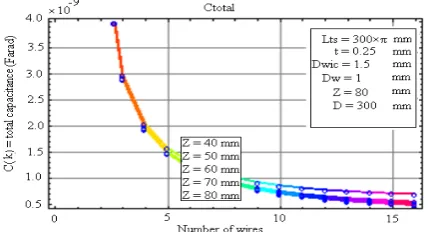
Fig. 15 Total capacitance of one single-layer turn of the MCG
for different air gaps between turn and liner.
central cylindrical liner (z) decreases, then the total stray capacitance value of single-layer k-CWFs in form of rectangular cross-section in OTC will increase. On the other hand, we can see decrease of total stray capacitance value of single-layer k-CWFs by increasing the number of single-layer CWFs in one turn. Therefore
considering above results, to decrease the total stray capacitance of single-layer k-CWFs, we should increase the number of CWFs in turn and air gap between CWFs and central cylindrical liner (z), on the other hand, we should decrease cross-section diameter of CWFs in coil turn (Dw) and turn length of CWFs(lts).
8 Verification of the Results
In this paper by considering the limitations and problems of the MCG explosion, in order to examine and study the results accuracy, the proposed method to calculate stray capacitance is compared with the results of reference [5]. In this case study we assume that the MCG has one turn with parameters as follow:
2
D 49.5*10 mm
w ic
− =
− , Dw 45 *10 2mm
−
= ,
2
t=22.5*10− mm, 3.5 r
ε = , 8.85*10 12 0
ε = − ,
6
π
β = ,
l 4.4925 *10 mm
ts = , Z 50 mm= .
By using equation (17) and with considering to above mention characteristics capacitance Css will be:
12 2
8.85 *10 * 4.4925 *10
/6
Css 0 d
1 (3.5) 2 49.5 *10
1 cos( ) 2 * ln
2 45 *10
π β
β
− −
= ∫ −
⎛ − ⎞
⎛ ⎞
⎜ ⎟
⎜ ⎟
− + ⎜ ⎜ − ⎟ ⎟
⎜ ⎝ ⎠ ⎟
⎜ ⎟
⎝ ⎠
=
3.894 pF.
Also by using the results of [5] with same above parameters we will have Css=3.934 pF.
So we can see that the calculated filament-filament capacitance Css by equation (17) is almost same as
filament-filament capacitance Css in reference [5].
9 Conclusions
In this paper, we presented a new method that called VRH model, in order to calculate stray capacitance between single-layer CWFs in OTC in form of rectangular cross-section in the MCG system.
The total stray capacitance of OTC of the MCG that include single-layer k-CWFs was obtained from two simplified equivalent circuits with distributed parameters. Final model includes the resistance serried with equivalent inductance of each CWF and paralleled with filament-filament capacitances between adjacent CWFs.
The presented method applies well and is true to calculate the stray capacitance of single-layer CWFs turn in form of rectangular cross-section. It was seen that the number of CWFs existing in one turn has effect on total stray capacitance of the MCG. The presented model is simple and the number of CWFs, diameter of CWFs existing in one turn of the MCG coil, kind of the insulating coating, thickness of insulating coating of CWFs and turn length of CWFs will be effective on total stray capacitance of the generator.
Also, in single-layer decrease the
D
w) and CW
between CW number of C
On the o results, we s one turn of th the MCG co simulation fo with compar
References
[1] Neube Helica 1nd e 2005. [2] Altgilb
M., M 1, New [3] Grandi capaci high-fr Industr 1165, [4] Yu Q.
capaci Finite Electro pp. 88 [5] Massa capaci Electro 1997. [6] Ajayi layer i 9, pp. [7] Duerdo
transfo 161-16 [8] Lu H
capaci IEEE pp. 11 [9] Daless “Calcu Voltag Zurich [10] Daless “Self-C Transf Vol. 22 [11] Grossn Circui York,
order to decre k-CWFs in on diameter of WFs length (
WFs and cent WFs in one tu other hand, by
aw that by in he coil, the ca oil will decrea or filament-fil e to results of
er A. A., Expl al Magnetic F ed., Vol. 1,
bers L. L., Br Magnetocumula w York, USA:
i G. and K tances of sing frequency ap ry application Sep./Oct 1999 . and Holme
tance modelin Element omagnetic Co -93, Feb. 200 arini A. and
tance of ind onics, Vol. 1 O., “H. F. Re inductance co 1055-1056, S oth W. T., ormer winding 67, Jun. 1946. H., “Experime tances in hi Trans. Power 05-1112, Sep. sandro L., Ca ulation of the ge Transform h, Zurich, Swit sandro L., Si Capacitance formers”, IEE
2, No. 5, pp. 2 ner N. R., its, Second E
1983.
ease total stra ne turn of the CWFs circula
(l )
ts and also
tral cylindric urn.
y considering ncreasing the C
apacitance val ase. Finally th lament capaci f reference [5]
losively Drive Flux Compress New York: rown M. D. ative generato
Springer-Ver Kazimierczuk
gle-layer air-c pplications”, ns, Vol. 35, N 9.
s T. W., “A ng of inducto
method”, ompatibility, 1.
Kazimierczuk ductors”, IEEE 12, No. 4, pp esistance of ro ils”, Proc. IE ep. 1973.
“Equivalent g”, Wireless E ental determi igh frequency r Electronics, . 2003. avalcante F. a e Stray Capac mers”, Int. Re tzerland, Mar ilveira F. an
of EE Trans. Po
2081-2092, Se Transformers Edition, McG
ay capacitance e coil, we sho ar cross-sectio o increase air cal liner (z) g the simulati CWFs numbe lue of one turn he verification itance is obtai
.
en Pulsed Po sion Generato Springer-Ver J. and Novac ors, 1nd ed., V
rlag, 2000. M. K., “St core inductors
IEEE Tra No. 5, pp. 11 A Study on st ors by using IEEE Tra Vol. 43, No k M. K., “S E Trans. Po p. 671-676, J ound-wire sing EE, Vol. 120,
capacitances Eng., Vol. 23, ination of st y transforme , Vol. 18, No and Kolar J. citance of Hi ep. 03/04, E . 2004. nd Kolar J.
High–Volt ower Electron
ep. 2007. s for Electro Graw-Hill: N e of ould on ( gap and ions er in n of n of ined wer ors, rlag, c B. Vol. tray for ans. 162-tray the ans. . 1, Self-wer July gle-No. of pp. tray ers”, o. 5, W., igh- ETH W., tage nics, onic ew-[12 [13 [14 [15 [16 [17 [18 [19 inte gen cou pap Un wit Ass hea res
2] Dowell P transforme 8, pp. 128 3] Chen R., V
W. G., capacitanc by embed Appl. Soc. 4] Yu Q., “R core indu materials” Compatib 2002. 5] Massarini
“Lumped multiple-l Electronic 6] Azaky A Electroma London, 1 7] Bartoli M “Modeling frequencie Denver, C 8] Snelling
Applicatio 1969. 9] Kazimierc
Componen 2009.
erests are in hig nerators, magn untry award of pers in electroni
niversity in Sep th the Niroo R sistant Professo ad of power
earch work is in
P. L., “Effec er windings”, 87-1394, Aug. Van Wyk J. D
“Application ce cancellation dding conduct
., pp. 2679-26 RF Equivalent uctors and ”, IEEE
ility, Vol. 44, A., Kazimier parameter ayer induc cs, Specialist C A. and Hawl
agnetic Field 1947. M., Reatti A.
g of iron p es”, IEEE In Co, pp. 1225-1 E. C., Soft ons, London czuk M. K., H
nts, U.K.: Jo
Majid Ez
Tehran, Ira of IAEEE the B.S. de from Electr Shiraz, Ira degree in Shahed Un gh-frequency m netic. He has f Iran. He has ics engineering Mohamm Tehran, Ir B.S. degr from Am 1989, the engineerin Institute o 1992 and engineerin ptember 1996. Research Instit or of Electrical
group at Shah n special electri
cts of eddy , Proc. IEE, V
1966. D., Wang S. a n of structu n for integrate tive layers”, 686, 2004.
circuit model characterizati Trans. Ele , No. 1, pp. 2 rczuk M. K. an
models for ctors”, Pro Conf., Baveno ley R., Fund Theory, Harr and Kazimier powder induc
dustry Applic 1232, 1994.
Ferrites, Pr , U.K.: ILI
High Frequen ohn Wiley &
zati Mosleh
an, in 1981. He in 2005 in Iran egree in electric
ronic Technica an, in 2005 electrical eng niversity in 200 machines, magn two invention published seve g.
mad Reza Besm
ran, in 1959. H ree in electric mirkabir Unive e M.Tech degre
ng from Unive of Technology, the Ph.D. degr ng from Newca From 1997 to tute in Iran. H
Engineering D hed University ical machine de
currents in Vol. 113, No. and Odendaal ural winding ed EMI filters in Proc. Ind.
ling of ferrite-ion of core ectromagnetic 258-262, Feb. nd Grandi G., single and oc. Power o, June 1996. damentals of rape Co Ltd.: rczuk M. K., ctors at high cations Conf.
roperties and IFFE Books,
ncy Magnetic & Sons, Ltd,
was born in eis a Member n. He received cal engineering al University of and the M.S. gineering from 9. His research neto cumulative ns and several eral books and
mi was born in
He received the al engineering ersity, Iran, in ee in electrical ersity of Indian , Delhi in June ree in electrical astle upon Tyne 1999, he was He is currently Department and y. His current esign. n . l g s -e c . , d r f , h f d , c , n r d g f . m h e l d n e g n l n e l e s y d t