Research Journal
Volume 12, No. 2, June 2018, pages 266-273
DOI: 10.12913/22998624/85662 Research Article
SOLUTION APPROACHES TO DIFFERENTIAL EQUATIONS OF MECHANICAL
SYSTEM DYNAMICS: A CASE STUDY OF CAR SUSPENSION SYSTEM
Tesfaye O. Terefe1, Hirpa G. Lemu2
1 School of Mechanical Engineering, Jimma University, 378 Jimma, Ethiopia, e-mail: [email protected] 2 Faculty of Science and Technology,University of Stavanger, N-4036 Stavanger, Norway, e-mail: [email protected]
ABSTRACT
Solution of a dynamic system is commonly demanding when analytical approaches are used. In order to solve numerically, describing the motion dynamics using dif-ferential equations is becoming indispensable. In this article, Newton’s second law of motion is used to derive the equation of motion the governing equation of the dynamic system. A quarter model of the suspension system of a car is used as a case and sinu-soidal road profile input was considered for modeling. The state space representation was used to reduce the second order differential equation of the dynamic system of suspension model to the first order differential equation. Among the available numeri -cal methods to solve differential equations, Euler method has been employed and the differential equation is coded MATLAB. The numerical result of the second degree of freedom, quarter suspension system demonstrated that the approach of using numeri-cal solution to a differential equation of dynamic system is suitable to easily simulate and visualize the system performance.
Keywords: Numerical method, Euler method, Differential equation, Suspension sys -tem, MATLAB, Mechanical system modeling.
INTRODUCTION
Numerical methods tend to emphasize the im-plementation of algorithms and provide system-atic methods for solving problems on computers by numerical calculations in a tabular data (ap-proximate data) or graphical representation and
figures. The process of solving problems gener
-ally involves starting from an initial data, using high precision digital computers, following the steps in the algorithms, for obtaining the results and the methods are approximate ones [12].
For all systems undergoing change, differen
-tial equations are used to properly describe the
system dynamics. The use of differential equa -tions is crucial in engineering, science and other
areas like economics and related fields. Nowa -days, there are many techniques available for
solving differential equations, which were devel
-oped through many years of studies particularly
in mathematics. Solving differential equations
based on numerical methods of approximation started before programmable computers existed. For large and complex system, in particular, dif-ferential equations are suitable for solutions em-ploying numerical methods that are simulated in
computers. This is because numerical simulations can represent the physical system and used to find
the nearly accurate solutions, which are not pos-sible analytically.
In the mechatronics system design and anal-ysis, in particular, mechanical systems, even in-cluding thermal or chemical nature, are exploited with analogies to electrical systems to design and
analyze [8]. The developments in programmable
computers have also made it possible to solve
complex systems of differential equations by writ
-ing simple program codes on a personal computer. Received: 2018.02.09
Thus, simulation of differential equation using di -verse methods and techniques in a numerical ap-proximation became popular.
For vehicle dynamics in general and the sus-pension system in particular, numerical method
based solution of differential equations has been
widely implemented [10]. The automobile indus
-try has closely studied, and still interested in, the vehicle suspension system because it is the mech-anism that physically separates the vehicle body from the wheels of the car to improve the ride
sta-bility, comfort and road handling of vehicles. To
better understand the suspension system perfor-mance, therefore, studies focusing on description of the road surface, modelling of the suspension
control system, identification of the performance
criteria and the like are reported [14]. The ve
-hicle is commonly modelled and simulated using the properties of its components such as springs, shock absorbers and linkages that connect the ve-hicle to its wheels. Generally, the traditional sus-pension system consists of springs and dampers that are referred to as passive suspension, while latter types that are externally controlled are re-ferred to as semi-active or active suspension
sys-tems. The suspension stores energy in the spring
and dissipates through the damper. Some design approaches for vehicle suspension systems focus on unconstrained optimizations for suspension system to identify the desirability of low
suspen-sion stiffness, reduced unsprung mass, and an
optimum damping ratio for the best controllabil-ity [2]. Others use numerical methods to partially automate the suspension system design process using genetic algorithm (GA) employing a
glob-al search technique [3, 9, 11]. The mathimaticglob-al
modeling and optimization of the suspension
sys-tem is mostly described by differental eqautions.
For instance, Thoresson and colleagues [18] pro
-posed a methodology that performs optimization
of off-road vehicle suspension system using gra
-dient based approach. Goga and Klucik [6] have used evolutionary computation method to opti-mize the vehicle suspension system by
develop-ing a half-car model in MATLAB.
The objective of the study reported in this ar
-ticle is to make a closer investigation of the
ap-plication of numerical solution to a differential
equation of mechanical system dynamics with focus on vehicle suspension system dynamics as a case study. Upon reviewing the previous
scien-tific works related to this area and exploring the methods of numerical solution to the differential
equation as well as the concept of suspension sys-tem, a mathematical model of a selected
suspen-sion system is described using differential equa
-tions. The application of the most popular numer
-ical method, such as Euler method to differential
equation of vibration analysis are studied and the
solution proposals are simulated using MATLAB tool using ode45 programming algorithm. The governing differential equation of the motion of a
quarter suspension system is derived using
New-ton’s Second Law.
Following this introduction section, the
ba-sics of numerical solution approaches of differ
-ential equations and different types of suspension systems in vehicles are briefly presented. Then,
a case study mathematical modelling approach
is illustrated and the differential equations that
describe the vehicle dynamics are derived. After discussing the results of the modelling done in
MATLAB, using plots of the simulation outputs, the article finally summarizes the content in the
conclusion section.
DIFFERENTIAL EQUATIONS AND
NUMERICAL METHODS
Differential equations are used to model and
describe problems that involve changes of some variables (exchanges of matter, energy, informa-tion or any other quantities, often as they vary in time and/or space) with respect to another. In
many real life situations, differential equations
that model the problem are too complex to solve
by integration exactly. However, there are differ
-ent categories of differ-ential equations for a spe
-cific problem type. A differential equation that is classified as ordinary differential equation contains one independent variable and its derivative. Many
mechanical systems are influenced by several un
-known variables and their derivatives in which a
differential equation category referred to as partial differential equation may be properly used. Fur -thermore, most real world problems are nonlinear, and hence, linearization is often used to transform the problem into a linear system and model by
us-ing a linear differential equation. This equation has
one degree of freedom of unknown function and its derivatives. Further categories exist depending
on their degree or order, i.e. classifications as first
order, second order, higher order or n’s degree of
(multi-degree) of differential equations.
Solving differential equations analytically is
As analytical solution of most of differential equa -tions is unknown, applying the numerical methods is necessary. On the other hand, in contrast to the general analytical solutions of initial value prob-lems that can be adapted to any initial conditions,
numerical method belongs to specific initial value
problem that changes the initial value in an
itera-tive calculation process. As Thohura and Rahman
[17] explained in their comparative study, differ
-ent techniques of numerical approaches are
avail-able for solving differential equations including
powerful numerical analysis software packages. For vibration analysis, in particular, numerical approaches are to be used if the free or forced vi-bration of a system cannot be integrated in closed
form for the differential equation governing the system. The numerical methods employed for this
purpose include the finite difference method, cen
-tral difference method, Euler method, the fourth-order Runge-Kutta method and stiff differential equation method [12]. These methods are based
on the approximation of the derivatives appearing in the equation of motion and the boundary
condi-tions are used for solving differential equacondi-tions in
numerical method.
SUSPENSION SYSTEM AND ITS
COMPONENTS
A suspension system is the main part of ve-hicles that can ensure the tire contact with the ground surface. It connects the vehicle chassis and wheels physically, transmits all loads from the ground to vehicle body, and enables the ve-hicle steering, braking and driving systems. It consists of wheels and tire, springs and shock ab-sorbers and linkages [14].
The suspension system is one of the most im
-portant systems in a vehicle because it ensures driving comfort by the vertical motion of the ve-hicle, which depends on the quality of the contact between the tire and ground surface [1].
Suspension systems are mainly classified as
passive, semi-active and active, and these categories
are briefly explained in the following subsections.
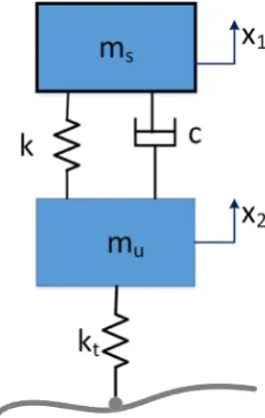
Passive suspension system
A passive suspension system, i.e. a system without energy source [7] is one of the conven-tional systems containing springs and shock ab-sorbers (Fig. 1). As illustrated, this suspension system has been commonly modelled with two degrees of freedom (x1 and x2) for the motion of
the sprung (ms) and unsprung (mu) masses sup-ported by the suspension system. Considering a quarter model of a car, the constants k and kt
represent the stiffness models of the suspension spring and the tyre stiffness respectively.
While springs have linear or nonlinear charac-teristics, shock absorbers (dampers) exhibit non-linear behavior [20] in terms of the relationship between force and relative velocity. Although this
type of suspension system does not fulfill all ex
-pectations about comfort and safety, it is widely used because it is one of the simplest designs and hence is cheap.
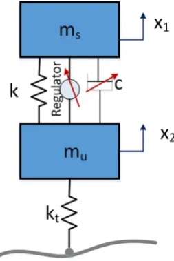
Semi-active suspension system
This suspension system type (Fig. 2) contains,
instead of passive shock absorber, an active shock absorber that is automatically controlled by an
in-tegrated regulator. Because of this device, the sus
-pension system becomes semi-active and it offers
some advantages in case of extreme driving
condi-tions [13, 19]. Earlier versions of semi-active sus
-pension systems were regulated by adjusting the resistance to fluid flow through oil orifices, which
is too slow for the speed of the mechanical motion
[21]. Latter applications, however, use electrorhe
-ological and magnetorhe-ological fluids, which are smart materials made by mixing fine particles into a low viscosity liquid [4]. To study the perfor -mance of semi-active suspension systems, several models are developed and reported in the litera-ture [16]. Compared with the fully active system the semi-active suspension requires less energy, it is cheaper and it is simplest in design.
The fully active suspension system
The fully active suspensions system (illus -trated in Fig. 3), beside normal components, contains also an actuator, sensors and central processing unit (CPU). Sensors measure the acceleration and the programmable CPU com-putes and guides the actuator that produces the
additional forces when desired. Thus, this sus
-pension system has better benefits over the other
types because of its adaptability to the road
pro-file while driving. However, the passive system
is more widely used because of the simplicity and comparable lower weight [13].
The purpose of all the suspension system types briefly presented above is to isolate the
forces arising from the road by ensuring high lev-el of manageability and convenience.
The car motion exposes it to a multitude of
dynamic forces such as aerodynamic forces, car vibrations, weather conditions and surface
rough-ness induced vibrations. These vibrations are
harmful to the passenger with a negative impact on the experienced comfort. A suspension sys-tem, thus, must meet several functions including:
comfort, safety and handling. To fulfil these and
other requirements, it is necessary to minimize the vertical acceleration and vertical relative dis-placement between sprung mass and wheel, and keeping vibration levels of the suspension system below the threshold imposed by the established natural frequency [15].
MATHEMATICAL MODELLING OF
VEHICLE SUSPENSION SYSTEM
A mathematical model is a description of a
system using equations. Differential equations constitute a major field of study in mathemat -ics with wide applicability in problems of engi-neering in mechanical, electrical circuits, civil engineering etc. Among others, the evolution of
processes that are deterministic, differentials and dimensional finite are studied. In this article, a
mathematical model is used to describe and study the performance of the suspension using a system
of two simple differential equations of order two.
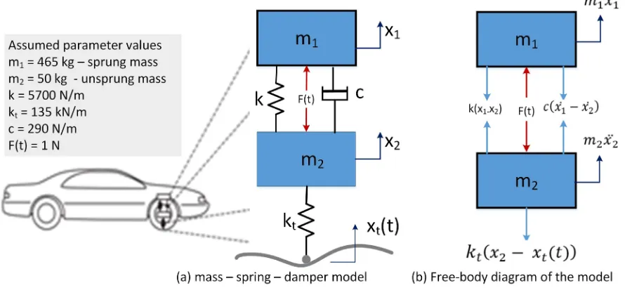
Figure 4 shows a model of the quarter of a car
suspension system. To study the dynamic perfor
-mance of the model, the free body diagram of the quarter of the car mass (sprung mass) m1 and the mass of the wheel–tire–axle assembly (unsprung mass) m2 are shown in Fig. 4(b).
The spring constant k represents the elastic
-ity of the suspension spring and the spring kt rep-resents the elasticity of the tire. x0(t) is the dis-placement input due to the surface irregularity of
the road. The actuator force, F, applied between
the sprung and unsprung masses is controlled by feedback and represents the active components of the suspension system [5].
In this model, it is assumed that the mass m1 moves faster than the mass m2, and the elongation of the spring k is x1 - x2. The force exerted by the
spring k on the mass m1 is downward, as it tends to restore to the unreformed position. According to Newton’s third law, the force exerted by the spring k on the mass m2 has the same magnitude, but opposite in direction. Other spring forces and Fig. 2. Illustrative model of a semi-active suspension
system
damping forces can be determined using the same logic. The gravitational forces are not included in the
free-body diagrams in Fig. 4.
Applying Newton’s second law, the equations of motion for the displacement x1 and x2 are expressed as: (1)
(2) Rearranging the equations into the standard input - output form
(3)
(4)
This can be expressed in the second order differential equation form as
(5) where a sinusoidal input xt(t) = sin (t) for the road profile is considered for the analysis.
Numerical Solution: Euler Method
As mentioned earlier in this article, the mathematical models of the dynamic system are expressed in
terms of differential equations (Eqn. 5). In particular, state-space representations take the form of sets of
first-order differential equations, where numerical solutions of these equations are implemented by nu
-merical integration of the first derivatives of the state variables. Therefore, the nu-merical solutions of the
responses of dynamic systems such as the one formulated above are obtained by numerical integrations.
Among the diverse methods of numerical approach to solve the differential equation, Euler’s meth
-od, modified Euler’s meth-od, Runge-Kutta method and stiff methods are those widely used in mechani
-cal system modelling and simulation. Euler methods for differential equation is selected and employed
for this case study as the approach of numerical solution to the governing equation of motion of the quarter car suspension.
Eigen values and Eigen vectors of a system are key elements for solving frequencies and mode shapes of dynamic systems. For large order systems of multi-degree of freedom, computing the Eigen values is more difficult and tedious because of its higher order. The space state representation helps to reduce the degrees of the higher orders of equation to the first order of differential equation. Using Euler
method as a numerical method to solve differential
equations, the space state form of damped multi-degree of freedom of a vibration of the automobile quarter suspension model is expressed as a forced response of a damped linear system as:
M(ẍ) + C(ẋ) + K(x) = F(t) (6)
To solve the formulated differential equation (Eqn. 5) using Euler method, simple MATLAB program is coded and simulated. The response in
terms of the displacement of the sprung and un-sprung masses is plotted in Figs. 5 and 6.
Numerical Simulation of the Time Response
To find the numerical solution of the state
space form, the ode45 function in MATLAB soft
-ware was used, a code which examines the use of numerical integration to simulate and plot the response of a vibration of the dynamic system.
As demonstrated, simulation is much easier way to obtain the systems response when com-pared, for example, to computing the response
by modal decomposition. The modal decomposi
-tion approach is needed to perform design of the dynamic system, to get insight into the dynamics of the system, and to check numerical solutions.
Likewise, the numerical solution may also be
used to check analytical works.
BRIEF DISCUSSION OF RESULTS
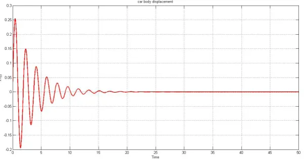
The response of suspension system for the
sprung and unsprung masses are plotted in Fig. 7
and Fig. 8 respectively. The response of car body
oscillation (Fig. 8) shows that the system is stable but needs some time to settle down and the
set-tling time is moderate. The vibration will be only
transparent to the passenger during the settling Fig. 5. Displacement x1 response for sprung mass Fig. 6. Displacement x2 response for unsprung mass
time. This means the passengers sitting in the auto -mobile will feel some amount (approx. 30% of the total time taken for this simulation) of vibration at the starting of the car, it goes decreasing gradually and becomes stable. In order to eliminate or reduce vibration at the settling time a feedback controller can be added into the system to improve the
perfor-mance of the suspension. This allows the suspen
-sion system exhibit good comfort by dissipating the vibration energy through the damper.
As can be observed from the response plot in Fig. 8, the suspension system is vibrating highly at the initial time (very short time with high vi-bration) and then comes to a normal sinusoidal motion in which the damper can dissipate out the vibration from the system to prevent it passing to the passenger or to the sprung mass.
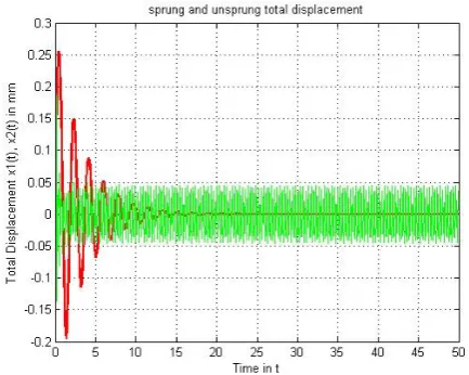
The overall system response (Fig. 9) shows
that the suspension system (unsprung mass) is
subjected to uniform vibration after settling time. This indicates that improvement measures to the
system is required in order to provide a comfort-able, safe travel and to extend the service lifetime of suspension system.
CONCLUSION
This article presented a study conducted on
a dynamics (mechanical) system simulation
ap-proach using numerical methods. The system, specifically the suspension system of a car, is expressed by differential equations and numerical
method is used to solve by programming in MAT
-LAB. In particular, the ode45 algorithm is used
to simulate the system model and observe the re-sponse or the dynamic condition of the system.
The contribution of this work is primarily educational, especially in the field of Applied
Mechanics and Dynamic system of mechani
-cal engineering. The modelling approach using differential equations and the solution approach employing Euler method are demonstrated. The
simulation outputs given in plots of system re-sponse contribute to better understanding of the system performance.
REFERENCES
1. Allen, R., Magdaleno, R., Rosenthal, T., Klyde, D. et al., Tire modeling requirements for vehicle dy -namics simulation, SAE Technical Paper 950312, 1995, https://doi.org/10.4271/950312.
Fig. 8. Response of the suspension system (unsprung mass)
2. Alleyen, A. and Hedrick, J. K., Nonlinear adaptive control of active suspensions, IEEE Trans. Control Systems, 3, 1995.
3. Baumal, A.E. McPhee, J.J. and Calamai, P.H., Ap -plication of genetic algorithms to the design opti-mization of an active vehicle suspension system, Computer Methods in Applied Mechanics and En -gineering, 163 (1–4), 1998, 87-94.
4. Boelter, R. and Janocha, H., Performance of long-stroke and low-long-stroke MR fluid damper. In: Pro -ceedings of SPIE 3327, Smart Structures and Ma -terials 1998: doi: 10.1117/12.310693.
5. Esfandiari, R.S., Modeling and analysis of dynam -ic system, 2nd ed. USA, NY, CRC press, 2014. 6. Goga, V. And Klucik, M., Optimization of vehicle
suspension parameters with use of evolutionary computation, Proceedia Engineering, 48, 2012, 174-179: doi.org/10.1016/j.proeng.2012.09.502. 7. Jayachandran, R. and Krishnapillai, S. Modeling
and optimization of passive and semi-active sus-pension systems for passenger cars to improve ride comfort and isolate engine vibration, Journal of Vibration and Control, 19(10), 2012, 1471–1479: doi: 10.1177/1077546312445199.
8. Karnopp, D.C., Margolis, D.L. and Rosenberg, R.C., System dynamics: modeling, simulation, and control of mechatronic systems, 5th ed., 2012, John Wiley & Sons, NJ.
9. Khajavi, M.N., Notghi, B. And Paygane, G., A multi objective optimization approach to optimize vehicle ride and handling characteristics, Interna-tional Scholarly and Scientific Research & Innova -tion., 4 (2), 2010, 502-506.
10. Kortüm, W. DLR., Review of multibody computer codes for vehicle system dynamics, Vehicle Sys-tem Dynamics, 22(1), 1993, 3 – 31.
11. Mitra, A.C., Desaib, G.J., Patwardhan, S.R., Shirke, P.H., Waseem M.H. Kurne Nilotpal Baner -jee, Optimization of Passive Vehicle Suspension System by Genetic Algorithm, Procedia Engineer -ing, 144, 2016, 1158-1166. https://doi.org/10.1016/ j.proeng.2016.05.087.
12. Rao, G.V., Rao, T.R.M., Rao, K.S. and Purushottam,A., Analysis of passive and
semi-ac-tive controlled suspension systems for ride comfort in an omnibus passing over a speed bump, Interna-tional Journal of Research and Reviews in Applied Science, 5, 2010.
13. Sharp, R. S. and Hassan, A. S., The relative per -formance capabilities of passive, active and semi-active car suspensions, Proceedings of Institution of Mechanical Engineers 20(D3), 1986, 219-228. 14. Sharp, R.S. and Crolla, D.A., Road vehicle suspen
-sion system design - a review, Vehicle System Dy -namics, 16(3), 1987, 167 – 192.
15. Shirahatti, A., Prasad, P.S.S. Panzade, P. and Kulkarni, M.M., Optimal design of passenger car suspension for ride and road holding, Journal of Brazilian Society of Mechanical Science and En -gineering, vol. 30(1). http://dx.doi.org/10.1590/ S1678-58782008000100010.
16. Spencer, B.F., Dyke, D.J., Sain, M.K. and Carlson, J,D., Phenomenological model of a magnetorheo -logical damper. Journal of Engineering Mechanics, 123(3), 1997, 230–238.
17. Thohura, S. and Rahman, A., Numerical ap -proach for solving stiff differential equations: A comparative study, Global Journal of Science Frontier Research Mathematics and Decision Sci -ences, 13, 2013.
18. Thoresson, M.J., Uys, P.E., Els, P.S. and Snyman, J.A., Efficient optimisation of a vehicle suspen -sion system using a gradient-based approxima-tion method, Part 1: Mathematical modelling. Mathematical and Computer Modelling, 50, 2009, 1421 – 1436.
19. Verros, G., Natisiavas, S. and Papadimitriou, C., Design optimization of quarter-car models with passive and semi-active suspensions under random road excitation, Journal of Vibration and Control, 11, 2005, 581–606.
20. Wallaschek, J., Dynamics of non-linear automobile shock-absorbers, International Journal of Non-Lin -ear Mechanics 25, 1990, 299-308.