A Review on Fading & Roadmap to its Realization
Dinesh SharmaDoctoral candidate UTU, Dehradun (INDIA) [email protected]
R.K.Singh Professor (OSD) UTU,
Dehradun (INDIA) [email protected]
Abstract — In these days the wireless communication requirements are increased according to customer requirements. The requirements are to have high voice quality, high data rates, multimedia features, low weight communication devices etc. But to provide these features to customers the wireless communication channel suffers from some problems. The main problem is fading which occurs due to the effect of multiple propagation paths, and the rapid movement of mobile communication devices. In a typical wireless communication environment, multiple propagation paths often exist from a transmitter to a receiver due to scattering by different objects. Signal travels in different paths can undergo different attenuation, distortions, delays and phase shifts. So, this is necessary to reduce the problem of fading. One effective solution is proposed for wireless system named diversity, with out the requirement of extra power or extra bandwidth. This paper discusses about the characteristics of fading models and a broad classification of various diversity techniques.
Key Words — Fading, Large scale fading, Small scale fading, Diversity.
I I
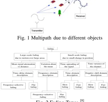
NTRODUCTIONThe scenario of mobile communications is rapidly amending according to the way people interact in their daily lives. Now a day the wireless communications services provide customers or users the connectivity in no time almost anywhere they go. It has made a tremendous change on the lifestyle of a human being and provides high speed mobility for voice, video as well as data traffic. The old traditional equipments mostly are being replaced by cable transmission. In the same way, the point-to-point microwave circuits indirectly we can say the backbone of the telephone network are being replaced by optical fiber. Another type of example is occurring today in telephony, where wireless technology is slowly replacing the use of the traditional wired telephone network. The initial plan, manufacturing and exploitation of technological infrastructure come along with a high cost and this may hamper manufacturers to test their initial designs. The manufacturers always look for different alternatives to avoid high costs by taking initial responsibility before the actual design. The best alternative is simulation of a real wireless system. The main advantage of simulation is that they could allow less initial expensive testing of designs. They could require previous investments on computing resources [1].The wireless channel can be described as a function of time and space and the received signal is the combination of many replicas of the original signal impinging at receiver (RX) from many different paths
[2-as multipath. If either the transmitter or the receiver is moving, then this propagation phenomena will be time varying, and fading occurs. In addition to propagation impairments, the other phenomena that limit wireless communications are noise and interference. It is interesting to notice that wireless communication phenomena are mainly due to scattering of electromagnetic waves from surfaces or diffraction, e.g. over and around buildings. The design goal is to make the received power adequate to overcome background noise over each link, while minimizing interference to other more distant links operating at the same frequency [6]. The problem of fading is solved by using diversity. Diversity is a influential technique to conquer the effects of flat fading by combining multiple independent fading paths. Basic concept is to send same information over independent fading paths and Paths are combined to mitigate the effects of fading.
II. F
ADING AND ITST
YPESFig. 1 Multipath due to different objects
Fig.4 Large scale and small scale fading and the impulse response function of the channel hc(t)
r(t)= s(t)hc(t) (1)
The received signal is the product of two random variables [12]
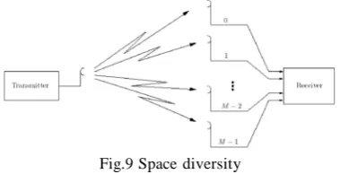
Fig. 2 Fading Types[8]
It is caused by path loss of signal as a function of distance and shadowing by large objects such as buildings, intervening terrains, and vegetation. Shadowing is a slow fading process characterized by variation of median path loss between the transmitter and receiver in fixed locations. In other words, large-scale fading is characterized by average path loss and shadowing [8-11] for more details [13].
Fig.3 Large Scale fading
On the other hand, small-scale fading refer to rapid variation of signal levels due to the constructive and destructive interference of multiple signal paths (multi-paths) when the mobile station moves short distances. Depending on the relative extent of a multipath, frequency selectivity of a channel is characterized (e.g., by frequency-selective or frequency flat) for small-scaling fading. Meanwhile, depending on the time variation in a channel due to mobile speed (characterized by the Doppler spread), short term fading can be classified as either fast fading or slow fading. The relationship between large-scale fading and small-large-scale fading is illustrated in Figure 4 [7]. In order to discuss the main differences between large-scale and small-scale fading, let us consider a received signal, which is represented by the convolution between the transmitted signal s (t)
r(t) = m(t) . r0(t) (2)
Where m(t)is the large-scale fading component, and r0(t)
the small-scale fading component. m(t) is the local mean of the received signal, usually characterised by a lognormal probability density function, which means that the magnitude, measured in decibel, has a Gaussian probability density function r0(t) is sometimes referred to
as a multipath fading [8].
(A) Wireless Small-scale propagation models
The small scale fading is due to small change in position and it describes short-term, rapid amplitude fluctuations of the received signal in a short period of time. The interference between two or more multipath components that arrive at the receiver while the mobile travels a few wavelengths combine at the receiver, and the resulting signal can rapidly vary in amplitude and phase [14]. The type of fading, experienced by the mobile, depends on the following factors [15]:
(i) Multipath propagation: Reflective surface and objects cause scattering creates a variation in amplitude, phase, and time delay. The random phase and amplitude of the different multipath components cause fluctuations in the signal strength.
(ii) Speed of the mobile: Due to the effect of different Doppler shifts on each of the multipath components ,The mobile is in relative motion between the transmitter and the receiver causes random frequency modulation
(iii) Speed of surrounding objects: The surrounding environment changes the multipath components because of varying Doppler shifts for all multipath components.
(iv) Bandwidth of the signal: The signal at the receiver
can distort if the transmitted signal bandwidth is greater than the flat-fading bandwidth of the multipath channel.
(a) Time delay signal spread: Flat Fading or frequency non selective fading
Fig.5 Flat-Fading and its channel characteristics[8] In a flat-fading, the spectral characteristics of the transmitted signal are conserved at the receiver, and the channel does not cause any non-linear distortion due to time dispersion [16]. Multi path causes slow gain fluctuations. The strength of the received signal changes slowly in time due to the slow gain fluctuations.
Here Bs<< B or Ts>> (3)
Where Bsis the bandwidth of the transmitted signal, Bc
is the coherence bandwidth of the channel Ts is the
symbol’s period, and is the rms (root mean square)
delay spread of the channel.
(b) Time delay spread: Frequency-Selective Fading
Frequency selective fading is just Opposite to the flat fading. if the channel has a constant gain and a linear phase response over a bandwidth that is much smaller than the bandwidth of the transmitted signal, this channel causes frequency selective fading on the received signal [16]. In this fading type the channel impulse response has a timegreater than the symbol’s period. When this occurs, the received signal includes multiple versions of the same symbol, each one attenuated (faded) and delayed. As a consequence, the received signal is distorted, that is, the channel produces inter-symbol interference. In the frequency domain, this means that certain frequency components in the received signal spectrum have larger gains than others (Fig. 6). For frequency selective fading, the spectrum of the received signal has a bandwidth that is greater than the coherence bandwidth BC . In this case, we say that the channel is frequency selective.
Fig.6 Frequency selective fading and its channel characteristics [8]
To summarize, a signal undergoes frequency selective fading if
Bs> Bc or Ts< (4)
The spectrum S(f) of the transmitted signal has a bandwidth greater than the coherence bandwidth Bcof the
channel; in the time domain, the transmitted symbol is
(c) Small-scale fading effects due to movements (Doppler Spread)
While the multipath effects described in the previous Section depend on the static geometric characteristics of the environment surrounding the transmitter and the receiver, the Doppler spread is caused by movements in the environment [17]. In a fast fading channel, the channel impulse response changes rapidly within the symbol duration .The coherence time is a statistical measure of the frequency range where the channel can be considered
“flat” [15]. If the coherence time is shorter than the
symbol duration of the transmitted signal, then the signal undergoes fast fading. In the frequency domain, signal distortion due to fast fading increases with the increasing in the Doppler spread relative to the bandwidth of the transmitted signal [2-3,18-19]. Therefore, the signal undergoes fast fading if
Bs< BD or Ts> Tc (5)
Where Tc and BD are the coherence time and the
Doppler bandwidth (i.e. the width of the Doppler power spectrum), respectively . Note that in the case of a frequency selective, fast fading channel, the amplitude, the phase, and the time delay of each of the multipath components are different for each component. A classic example of a signal travelling over a fast fading channel was the Morse code signalling, used in the HF frequency band: since the signalling exhibited a very low data rate, its bandwidth was very large, larger than the channel’s coherence bandwidth. In a slow-fading channel, the channel impulse response changes at a rate much slower than the transmitted signal. In this case, the channel can be assumed static over several symbol intervals. In the frequency domain, the Doppler spread is much less than the bandwidth of the signal [2-3, 18-19]. To summarize, a signal undergoes slow-fading if [8]
Bs>> Bc or Ts<< Tc (6)
IV. R
OADMAP TOR
EALIZEF
ADINGThere are three techniques are there which can be used individually to improve the signal quality over small scale times and distances. Those are equalization, Diversity and channel coding. These three techniques are used to improve radio link performance but the approach, cost, complexity and effectiveness of each technique varies widely in practical wireless communication systems [27].
(ii) Channel coding: It improves the small scale link performance by adding redundant data into the transmitted message so that if an instantaneous fade occurs in the channel, the data may still be recovered at the receiver. At the base band portion of the transmitter , a channel coder maps the user’s digital message sequence into another specific code sequence containing a greater number of bits than originally contained in the message. The coded message is then modulated for transmission in the wireless channel.
(iii) Diversity: Diversity is another technique used to compensate for fading channel impairments and is usually implemented by using two or more receiving antennas. The evoling 3G comman air interfaces also use transmit diversity,where base station may transmit multiple replicas of the signal on spatially separated antennas of frequencies. As with an equalizer, diversity improves the quality of a wireless communication link without altering the common air interface and without increasing the transmitted power or bandwidth. however ,while equalization is used to counter the effects of time dispersion (ISI) , diversity is usually employed to reduce the depth and duration of fades experienced by a receiver in a local area in which are due to motion. In simple words we can say Diversity is the technique used to compensate fading radio channel in wireless communications systems. Multiple copies of the same information is received at the receiver, the information is transmitted over two or more virtual communication channels. Thus the main or basic idea of diversity is repetition or adding redundant information. In practical the diversity exists at the receiver side so the decisions made by the receiver and are unknown to the transmitter. In this paper we will discuss only the technique Diversity.
(A) Types of Diversity Techniques: There are five diversity techniques used to get rid from the fading impairments [22, 23, and 27]. Those are
(a) Frequency Diversity: In this technique the same information signal is transmitted over different carriers, the frequency separation between carriers must be greater than or equal to the coherence bandwidth. Frequency diversity is often empolyed in microwave line of sight links which carry several channels in frequency division multipxex mode (FDM). This technique has the disadvantage that it is only requires spare bandwidth but also requires that there be as many receivers as there are channels used for the frequency diversity.
Fig.7 Frequency diversity
(b) Time Diversity: In this technique the information signal is transmitted many times in regular intervals. The separation between the transmit times should be greater
than the coherence time. The interval depends on the fading rate. The coherence time interval increases with the decrease in the rate of fading. One modern implementation of time diversity involves the use of the RAKE receiver of spread spectrum CDMA, where the multipath channel provides redundancy in the transmitted message.
Fig. 8 Time diversity
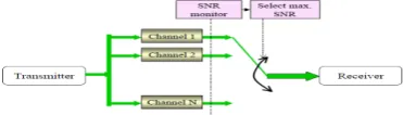
(c) Space Diversity: Space diversity is also known as
antenna diversity and it is the most popular diversity used in wireless communication. This concept is also used in base station design. In space diversity, there are multiple receiving antennas placed at different spatial locations, resulting in different receiving signals.
Fig.9 Space diversity
(d) Polarization diversity: In this technique, the electric and magnetic fields of the signal carrying the information are modified and many such signals are used to send the same information. Thus orthogonal type of polarization is obtained. It enables detection of smaller radar cross-section (RCS) targets, and avoids the physical, mathematical, and engineering challenges of time of-arrival coherent combining. The advantage of polarization diversity over spatial diversity is that diversity gains are possible with collocated antennas.
Fig. 10 Polarization diversity
k
M
the Base station two techniques are used one is; in time Angular Diversity, in which it combines the two received signals at the same time in order to achieve Diversity
P(
()k)((t))AM
P
k t Ak1
(9)
Gain. It is a microscopic diversity. The second is Out of time Angular Diversity in which the signal strength of the mobile unit is constantly monitored at the base station by each beam of a multi-beam antenna system. The strongest beam is used for the traffic link at the time. If the diversity is applied at the Mobile unit Each directive antenna will separate a different angular component and signals received from different directive antennas are uncorrelated. Here, directional antennas are used to create independent copies of the transmitted signal over multiple paths.
(B) Combining methods of Diversity: Several copies of the transmitted signal which under go fading is combined by the diversity to increase the overall received power. Depends on the combining methods different diversity techniques are there. Those combining methods are as follows.
(a) Combining method for macroscopic diversity (i) Selective Combining method: In Macroscopic diversity only the received signal is considered. the mean may vary as a result of as a result of long term fading. Selective diversity combining is chosen to primarily reduce long term fading. It is because of the fact that by combining two signals received from different sited transmitting antennas the local means of the two signals at any given time interval are rarely the same.
Fig. 11 selection combining method
(b) Combining Techniques for Microscopic
Diversity: Microscopic Diversity deals with short term fading. In this case the principle is to obtain a number of signals with equal mean power through the use of diversity schemes. Three types of linear diversity combining schemes are popular:
(i) Selective Combining: The algorithm for selective diversity combining is based on the principle of selecting the best signal among all of the signals received from different branches, at the receiver end [24].
REC
REC
Fig. 12 selective combining method
Consider m branches assuming that the signal to noise ratio achieved on each branch is ϒi(i=1,2…M). Further, assume that the received signal on each branch is independent and Rayleigh distributed with mean power of
2σ2
. Each ofγiare distributed exponentially. The pdf ofγi
is given by
P(
)(
i1/
)ex
0p
(/
)
i
0 (10) Assume that there are M different signals obtained, byusing a macroscopic diversity scheme and the local mean of the Kth signal, mk(t) is expressed in decibels and
denoted byωk(t) [24]. The k signals are distinguishable
Where i=1,2…..M, γi ≥ 0 and γ0 =2σ 2(Eb/N0) is the
mean Signal to Noise ratio. Eb/N0 is the mean Signal to Noise ratio without fading. The CDF of SNR is thus
during reception either by their frequency, their angle of
arrival, or their time-division multiplexing differences, P(
)(i)1
exp
(/p x) dx0
i
0(11) which are detectable. ωk(t) has a lognormal distribution
.and the probability that the local mean in dBs, ωk(t),is less than a level A, in dBs , is :
The combining method is by picking the maxi(γi).The probability that the selected SNR of the branch is less thanγis
P(γ)=Pγ(maxi γi≤ γ) = Pγ(γ1≤γ, γ2≤γ,
A 1
P (())e x pt A
()k k2
M
d
2 k
2 () 2
k
k
(7)
γ3≤γ,……..γM≤γ,)=
i1
1
exp(
/
i)
0 (12) 1 1
2 2
e r f
A
k
2
k
(8) Or
P(
)(1
ex
p(/
)
)
i
0 (13) Where
andk
kare the mean and the standardThe performance of diversity systems is usually measure by comparing the CDFs of various combining methods. deviation in decibals of the long term signal. If all long
term signals are uncorrelated, then the probability that a selectively combined long-term
Signalω(t) will be less than a level A is as follows:
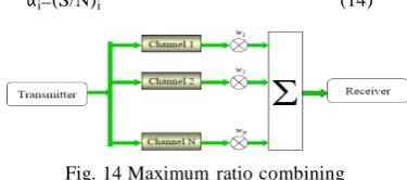
(ii) Maximum Ratio Combining (MRC): In this diversity technique all the branches are used simultaneously. The branch selection is based on weight of the signal that means Each of the branch signals is weighted with a gain factor proportional to its SNR. Co-phasing and summing is done for adding up the weighted branch signals in phase. The gain associated with the ith branch is decided by the SNR of the corresponding branch. i.e.,
αi=(S/N)i (14)
Fig. 14 Maximum ratio combining
In the MRC scheme requires that the signals be added up after bringing them to the same phase, If is the signal envelope, in each branch then the combined signal envelope is given as
M
(ii) Feed back combining: It is a predetection combining technique that utilizes feedback as a reference signal in place of a local oscillator as shown in fig 11. F1 is a narrow band pass filter centered at f2-f6 and covering
2∆f.F2 is a band pass filter BPF centered at f2. L1 is a
limiting amplifier and M1 and M2 mixers. It is also known as granuled combiner [23].
Fig. 16 Feed back combining circuit
the received input signal at the receiver is divided into two branches. One of The outputs of first mixer M1 is given to filter F1 and the limiting amplifier. Te output from the
a
a
i
i1
(15) limiting amplifier and the received signal directly is given to the mixer two that is M2.
The main work in this is Branch weights optimized to maximize output SNR of combiner. Optimal weights are proportional to branch SNR. Resulting combiner SNR is sum of individual branch SNRs.
(iii) Equal gain combining: It combines the instantaneous fading envelopes of the individual branches which are having cophase at a common point.
• In EGC, each branch is co-phased and equally weighted.
• Easier to implement than MRC, but harder to analyze.
• Distribution of combiner SNR
• complicated for more than two branches.
• Hard to obtain Pout and Ps.
• EGC is about 1 dB worse in performance than MRC.
(c) Combining technique to reducing random phase:Random phase of the each branch when the signal receives at receiver is reduced by using this technique. The main effort is with the signal received i.e dividing the signal into two signals using a power divider circuit and combining those with a special circuit mean while the random phase can be reduced. There are mainly two feed combining techniques [22,24,26].
(i) Feed forward combining: A circuit that is used in feed forward combining is shown in fig [15]
Fig. 15 Feed forward combining circuit[23]
C
ONCULSIONIn this paper we have described fading models: one is large scale fading and another is small scale fading. The diversity is the best technique used to provide the receiver with several replicas of the same signal and this Technique is used to get better the performance of the radio channel without any changing the transmitted power. Different Diversity techniques have different merits and demerits depend on environments. So diversity schemes are selected according to the environment.
• Diversity is a powerful technique to overcome the effects of flat fading by combining multiple
Independent fading paths
• Diversity typically entails some penalty in terms of rate, bandwidth, complexity, or size.
• Both selection combining and MRC significantly reduce the impact of fading.
• SC vs. MRC offers different levels of complexity vs. performance.
• Performance analysis of MRC greatly simplified using MGF approach.
R
EFERENCES[1] Julio Aráuz, “Discrete Rayleigh Fading Channel
Modeling”,(http://citeseerx.ist.psu.edu/viewdoc/summary? doi=10.1.1.85.6033)
[2] Haykin, S.; Moher, M.;Modern Wireless Communications ISBN 0-13124697-6, Prentice Hall 2005.
[3] Bertoni, H.;Radio Propagation for Modern Wireless Systems, Prentice Hall, 2000.
[25] William C. Y. Lee, “Mobile Communications Design
fundamentals”, Wiley Series in Telecommunications, Second
edition,1993.
[26] M., K. Simon, and M., S. Alouini, “Digital Communication Over
Fading Channels: A Unified Approach to PerformanceAnalysis”, Wiley, New York 2000.
[27] T.S.Rappaport, “Wireless Communications-Principles and
nd [4] Saunders, S.; Antennas and Propagation for Wireless
Communication Systems, Wiley, 2000.
Practice” 2 edition.
[5] Vaughan, R.; Andersen, J.B.; Channels, Propagation and Antennas for Mobile Communications , IEE, 2003.
[6] S.Popa, N. Draghiciu, R. Reiz, “Fading Types in Wireless
CommunicationsSystems’’.
http://electroinf.uoradea.ro/reviste%20CSCS/documente/JEEE_2 008/JEEE_2008_57_Popa_1.pdf)
[7] Yong Soo Cho, Jaekwon Kim, Won Young Yang and Chung G.
Kang, “MIMO-OFDM Wireless Communications with
MATLAB”, 2010 John Wiley & Sons (Asia) Pt. Ltd.
[8] PAOLO BARSOCCHI, “CHANNEL MODELS FOR
TERRESTRIAL WIRELESS COMMUNICATIONS: A
SURVEY”
,(http://www.csd.uoc.gr/~hy439/lectures11/2006-TR-16.physical_layer_tutorial.pdf)
[9] W. C. Jakes, Jr., Microwave Mobile Communications. New York: John Wiley and Sons, 1978.
[10] Lee, W.C.Y., Mobile Communications Design Fundamentals, Indianapolis: Howard W. Sams & Co., 1986.
[11] Parson D., The Mobile Radio Propagation Channel, New York: Halsted Press (John Wiley & Sons, Inc.), 1992.
[12] Lee, W.C.Y.,”Elements of cellular mobile radio system, IEEE
Trans. Vehicular Technol., V-35(2), 48-56, May 1986.
[13] Dinesh Sharma, Purnima K. Sharma, Vishal Gupta, R.K.Singh, “A Survey on Path Loss Models used in Wireless communication System Design” in IJRTE Vol. 3, No.2 in 2010.
[14] Boithias, L., “Radio Wave Propagation”, McGraw-Hill, New
York 1987.
[15] Gibson, J.D., “The Mobile Communications Handbook”, CRC
Press 1996.
[16] Amoroso, F., “The Bandwidth of Digital Data Signals,” IEEE
Communications Magazine, vol.18, no. 6, November 1980,pp. 13-24.
[17] Clarke, R.H., “A statistical theory of mobile radio reception”,
Bell Syst. Tech. J., 47(6), 957-1000, Jul.-Aug. 1968.
[18] Hottinen, A.; Tirkkonen, O.; Wichman, R.; Multi-antenna Transceiver Techniques for 3G and Beyond. John Wiley and Sons, Inc., 2003.
[19] Paulraj, A.; Nabar, R.; Gore, D.;Introduction to Space- Time Wireless Communications. ISBN: 0521826152, Cambridge University Press, 2003.
[20] Richter, A.; Thomae, R.S.; Taga, T.; Directional Measurement and Analysis of Propagation Path Variation in a Street Micro-Cell Scenario, Proc. Of IEEE 57th Vehicular Technology Conference (VTC 2003-Spring), Jeju, Korea, April 2003. [21] Rustako, A.J.; Gans, M.J.; Owens, G.J.; Roman, R.S.;
Attenuation and Diffraction Effects from Truck Blockage of an 11-GHz Line-of-Sight Microcellular Mobile Radio Path, IEEE Tr. Vehicular Technology, Vol.40, No. 1, February 1991.
[22] M.,K. Simon, M.,S. Alouni, “A Unified Approach to the
Performance Analysis of Digital Communication over
generalized Fading Channels” , Proc. IEEE 86(9) ,1998,pp
1860-1877.
[23] NEELAM SRIVASTAVA, “DIVERSITY SCHEMES FOR
WIRELESS COMMUNICATION SHORT REVIEW” Journal of Theoretical and Applied Information Technology, Vol.15. No.2 page no.134-143, May 2010.
[24] William C.Y. Lee, “Mobile Communications Engineering
-Theory and Applications”, Secondedition, Tata Mc- Graw Hill
Publishing company limited, New Delhi,2008.
A
UTHOR’
SP
ROFILEMr Dinesh Sharma was born on 5th
Dec 1982 in Narnaul District Mohindergarh of Haryana (India).He received his M.Tech. degree in Communication Engineering from SHOBHIT University, Meerut, India. He is a Associate Member of the IETE. He has published several Research papers in national and international journals/conferences. He is presently research scholar in UTTARAKHAND TECHANICAL UNIVERSITY, Dehradun (INDIA). His present research interest is in Signal Processing and Wireless Communication.