Copyright © 2013 IJECCE, All right reserved
Block Diagonalization with Multiuser Beamforming for
Coordinated Multi-Point Transmission
Md. Hashem Ali Khan, Moon Ho Lee, Mumta Hena Mustary
Abstract — Coordinated Multi-Point transmission and reception (CoMP) technique is mostly required to reduce the inter-cell interference (ICI). It also increases the cell edge user throughput and improves the coverage. We apply block diagonal beamforming to downlink transmission, and assume perfect knowledge of downlink channels and transmit messages at each transmit point. Two different power allocation schemes are investigated for SVD, ZF and BD based multicell transmission.The SVD scheme achieves a suboptimal performance, butat a reduced complexity.In this paper, we study the performance of multiuser beamforming for differently in various CoMP scenarios. The simulations results indicate that the proposed scheme offers much higher performance gain compared with the CoMP-JP mode and reduce the complexity in comparison with BD scheme.
Keywords — Block Diagonalization (BD), Coordinated Beamforming, Joint Processing, CoMP, Zero-forcing.
I. I
NTRODUCTIONA multiuser MIMO system typically consists of a base station equipped with multiple antennas and a number of mobile users, each possibly equipped with multiple receive antennas. The base station transmits data to these mobiles users [1]-[2]. To eliminate or reduce interference, the base station is required to employ orthogonalization techniques. These orthogonalization techniques distribute signals to mobile users among different dimensions of resources and thus obtain a minimum interference between them. In this approach, the base station transmits signals to multiple mobile users by applying orthogonal
beamforming weights. As a result, each mobile user’s
beamforming weights lie in the null space of all other
mobile users’ channels. This is equivalent to having
orthogonal channels between different mobile users. Zero-forcing (ZF) and BD [3] are alternative low complexity transmission techniques. BD scheme is an attractive orthogonalization scheme for its low complexity and acceptable sum capacity [4]. Attention has been focused on improving the performance of BD under realistic scenarios. Accurate CSIT is clearly important for MIMO broadcast systems in order to achieve maximum throughput. When the receiver knows the channel perfectly and instantaneously feeds this information back to the transmitter using a finite number of bits, we have quantified the rate loss and have shown that increasing the number of bits linearly with the system SNR is sufficient to maintain a constant SNR loss with respect to perfect CSIT [5]. Further, we have established the advantage of BD relative to ZF in terms of feedback load, and the advantage of using quantized feedback as opposed to using analog feedback.
In [6], the impact of mutual coupling on BD performance in terms of sum rate capacity is addressed on the performance of a multiuser MIMO system employing BD scheme in terms of sum rate capacity.
For the multiuser MIMO downlink, the interference due to signals transmitted to other users is known at the transmitter, and in principle, a precoder could be used to essentially undo its effects. The primary drawback of such schemes is that their use of nontraditional coding leads to increased complexity at both the transmitter and receiver. Numerical results for the system SNR, sum rate, and bit error-rate (BER) are shown in [7]. If zero-forcing beamforming (ZFBF) is used, the feedback rate must be scaled with the number of transmit antennas as well as SNR in order to achieve rates close to perfect CSIT systems [8]-[9]. In such a system the transmitter emits multiple beams and uses its channel knowledge to select beamforming vectors such that nulls are created at certain users. Inaccurate CSI leads to inaccurate nulling and thus translates directly into multi-user interference and reduced SINR/throughput. Similar to the results in [9], it was shown that scaling the number of feedback bits approximately linearly with the system SNR is sufficient to maintain the slope of the capacity vs. SNR curve and achieve a rate that is a constant gap from the throughput of BD with perfect CSIT. In [10], the authors have shown that zero-forcing beamforming can achieve sum capacity only when the number of users is large and a scheduler that selects spatially semi-orthogonal users is used. In [11], the BD technique with a minimum mean square error vector precoding for achieving further gain in performance with minimal computational overhead was combined. Moreover, due to the QR decomposition based block diagonalization, dimension of the system being processed is reduced. BD is a generalization of zero-forcing beamforming for multiple stream transmission to each user. The scaling factor for BD offers an advantage over ZF in terms of the number of bits required to achieve the same sum capacity. In this paper, we study the performance of multiuser beamforming for various CoMP scenarios.
UE. Therefore, linear precoding in CoMP-JP is an optimized solution with relatively lower complexity requirements at both the access points (Aps) and the UEs.
In terms of downlink CoMP, two different approaches are under consideration: Coordinated scheduling, or Coordinated Beamforming (CBF), and Joint Processing/Joint Transmission (JP/JT). In the first category, the transmission to a single UE is transmitted from the serving cell, exactly as in the case of non-CoMP transmission [17]-[18].
Fig.1. CoMP-Joint processing
In CoMP-JP mode as shown in Fig.1, the data information to the UE is simultaneously transmitted from all APs under the control of the same eNodeB. The UE's data is distributed and jointly processed across the APs and the channel state information (CSI) is required for all the AP-UE pairs. Although CoMP-JP mode is incurring large system overhead, it can coherently or non-coherently improve the received signal quality and cancel actively interference for the UEs. The CoMP-JP mode can be used for serving one UE (SU) or multiple UEs (MU) using the given time/frequency resources at the same time.
Fig.2. CoMP coordinated beamforming
In the category of coordinated scheduling/beamforming as shown in Fig. 2, the data information to the UE is transmitted from its serving cell only but the cells in the CoMP set coordinate their transmission so that inter-cell interference can be reduced. Meanwhile, it is not necessary to share the UE's data information across multiple APs, which alleviates the heavy overhead on the network. To achieve the coordination, the UE needs to feedback information about the CSIs of the serving cell and the other cells in the CoMP set. CoMP-CBF mode can also increase the cell edge user throughput via interference management.
This paper is organized as follows. Section II describes the system model. In Section III, presents coordinatedbeamforming of CoMP-JP. In Section IV, presents complexity analysis. Simulation results are presented in Section V and conclusions are delivered in Section VI.
Notation: and denote transpose and Hermitian transpose operations, respectively. | · | and || · || represent the absolute value and norm of a vector or matrix.
II. S
YSTEMM
ODELConsidering the downlink joint processing/reception comprised of L cells in intra-eNodeB scenario, it is assumed that there are K users equipped with N antennasR and uniformly distributed at the edge of each cell. AP in each cell is configured with N antennas. For downlinkT CoMP, APs in different cells send the same signals which contain multiple data streams to multi-users. The APs belonging to the same eNodeB jointly receive the feedback information. In Fig. 3, we give an example of the downlink CoMP-JP MU comprised of three cells [22]-[23].
1
, 1,
H x H x
K
k k k i i k
i
y k K
(1)where, the channel matrix Hi are denoted by
1 2
Hkdiag h hk k hkL (2)
Fig.3. Block diagram of the multiuser system in CoMP where Hkdenote the NRLNTchannel matrix from the APs to the k-th UE, and hkirepresents theNRNTchannel gain from the i-th AP
1 i L
to the k-th UE.kdenotesthe NR1additive white Gaussian noise (AWGN) vector
with zero mean and universal variance2The transmitted signals can be written as
xk M si i (3)
The total power constraint is imposed by
2x t
E P
III. C
OORDINATEDB
EAMFORMING OFC
OMP-JP
In this section, we represent a novel block diagonalization method for multiuser MIMO systems. The BD algorithm is an extension of zero-forcing method for
T
HCopyright © 2013 IJECCE, All right reserved multiuser MIMO systems where each user has multiple
antennas.
A. Block Diagonalization
In this subsection, there is no need for complete diagonalization of the channel, and BD requires only block diagonalization where multiuser interference (MUI) is completely eliminated. The interference from other user signals is canceled in the process of precoding. CoMP gain depends much on the precoding scheme. BD based precoding is utilized when considering multiple receive antennas, and reasonable precoding complexity and performance gain compared with unitary precoding and ZF-BF precoding method. The received signal at the k-th MS, given as Eq. (1), is rewritten as
1
( ) H M ( ) ( )
K
i i k k i
i
y n s n n
1
( ) ( ) ( )
H M H M
K
i i i i k k i
i
s n s n n
(4)where the second term represents the CCI caused by the multiuser sharing the downlink resources. The principal idea of the block diagonalization is to find the beamforming vectors which can zero-force the CCI. The
key idea of BD is to precoder each user’s data xkwith
precoding matrix Mk, such that 0, for all and 1 ,
H Mi k i j i kK (5)
which means all multi-user interference will be eliminated. With the beamforming vectors satisfying Eq. (5), the CCI is completely eliminated and thus the k-th MS observes a point-to-point MIMO link with the base station. With a sum power constraint, the achievable throughput for the resulting block-diagonal system is
* *
2 2
H 0,
1
max log I H M H M
BD w i k i i i i
i k C * * 2 2 H 0, 1 1
max log I H M H M
K
k k k k s
w i k
i k k C
(6)whereCsrepresents the sum capacity of the system.Hkis defined as the channel matrix for all users other than user
k.
1, , 1, 1, ,
H HT HT HT HT T
k k k K
(7)
The zero inter-user interference constraint forces Mkto lie in the null space of Hk. The constraint of Eq. (4) can be rewritten as
0
H Mk k (8) Eq. (8) indicates that the beamforming vectors for the k-th mobile user should lie in k-the null space of Eq. (7). By applying singular value decomposition (SVD), the following is obtained
(1) ( 0)
0
0 0
Σ
H U k V V H
k k k k
(9)
whereΣkis the diagonal matrix with all non-negative singular values Hkto be its diagonal elements with a dimension equals to the rank of Hk.
(0)
Vk contains vectors
corresponding to the zero singular values and (1)
vk consists of the singular vectors corresponding to non-zero singular values. Thus, Vk(0) is an orthogonal basis for the null space of Hk.Vk(0)represented by
(0)
Vk as the block diagonalization precoding matrix Mk for the userk. So, the precoding matrix can be denoted as
(0) (1) (0) (1) (0) (1) 1/ 2
1 1 2 2
M V V V V V V
Λ
k K K (10) whereΛis a diagonal matrix whose element scale i the power transmitted into each of columns of Mk. The capacity of the BD [7] is
2
2 2
max log Σ
Λ I BD C
(11)
With the precoding matrix Mk, the effective channel
HM is block diagonal, which means all inter-user interference other than intra-user interference is eliminated. They form an orthogonal basis for the space of Eq. (7). The columns are the candidate beamforming vectors. To maximize the sun rate, the optimal power loading matrix should be applied using the water-filling method.
B. Zero-forcing Beamforming Algorithm
In this subsection, we design zero-forcing beamforming. The eNodeB selects the two UEs, the concatenated quantized channel vectors areHk H H1T T2 T. Then the
ZF matrix is
1 1/ 2
1/ 2
diag
diag
M H H H p G p
H H
k k k k
k
(12)
wherepk
p p1 2
Tis the vector of power normalization coefficients. For equal power allocation2 1 2 t k k P p g
, (13)
whereg denotes the k-th column of Gk k . The SINR of k-th UE is given by
2 2 0 SINR H H H k k k k
H i k k i k
p g
N p g
(14)whereN denotes the power of noise.0 And the UE rate is as follows
log 1 SINR
k k
R
2
2 0
log 1 H
H
H k k k
H i k k i k
p g
N p g
. (15)
C. Minimum Mean Squared Error (MMSE)
In this case the beamforming vectors are obtained in order to maximize the overall SINR at the receiver. The beamforming matrix Mkis then
1
1
M HH H HH
k k k k IN
whereis the signal-to-noise ratio (SNR), defined as the ratio between the maximum available power and noise power 2
n
. By denoting withAH Mk k, we can express
the SINR for each user’s signal at the receiver output as
,
2 2
2
,
A Ai i i
k
i j i n
k i
P SINR
P
. (17)IV. C
OMPLEXITYA
NALYSISIn this Section, we discuss the complexity of the generalized zero forcing-Gram Schmidt Orthogonali-zation (GZF-GSO) algorithm and compare with the conventional BD scheme. For the sake of simplicity, all users are assumed to have the same number of the receive antennas Nk andKNk NT. The complexities of the alternative methods are usually compared by the number of floating point operations (flops). A flop is defined as real floating operations, e.g. a real addition, multiplication, division and so on. One complex addition and multiplication involve 2 and 6 flops respectively. Other complex operations, e.g. division, are roughly regarded as complex multiplications.
For a m n complex-valued matrixAwith mn, its multiplication with another n p complex-valued matrixB
requires 8mnp flops. But when B has a special form the complexity reduces. For instance, whenB is a diagonal or block diagonal matrix, the complexity reduces to
4mn m1 flops. By treatingall operations as multiplications, the SVD operation on A takes about
2 2 3
24mn 48m n54m flops,the GSO on A takes
2
8m n2mn, the inversion operation onan mmtriangular complex-valued matrix takes about 2
4m m1 , the QR decomposition onA takes12m n flops. The water filling2
operation is always done in the real-valued domain but itdoes not have a fixed complexity. But in worst case, it takes up to at most2m26m
flop forwater filling over m eigenvalues [24].
The complexity computation of water-filling power allocation is
2 2 1 2K Nk 6KNk
(18)The complexity computation of QR-BD is given by [24]
2
2 KNk 2kNk 8KNT NT K 1 Nk Nk
. (19)
Fig.4. Comparison of the required flops versus the number of transmit antennas, NT
The complexity of these two steps will be obtained as 1 2
(20) WhenKNk NT,
H Hk *k
1
is multiplied by the block diagonal matrix, and then multiplied by *
Hk. However whenKNk NT, the *
*
1Hk H Hk k
reduces to 1
Hk
so that
only one matrix multiplication is enough.
Fig.5. Comparison of the required flops versus the number of users, K
In Fig. 4, we fix n2 and k2 while express the number of flops as a function of N . In the Fig. 5, we fixT
24
m andn2, the number of flops is expressed a function ofK. From Fig. 4 and Fig. 5, it obvious that GZF-GSO get a large advantage compared with BD. The larger NT orK, we can get the more significant difference. From Fig 5, we consider K10and the number of flops6, then the complexity reduce
6
100 60% 10
.
V. S
IMULATIONSR
ESULTSIn this section, we present the simulation results to illustrate the performance of proposed scheme. A multi-user MIMO system is simulated to evaluate the performance of the proposed multi-user beamforming scheme comparison to the conventional single user beamforming scheme. Fig. 6 shows BER performance of a multiuser MIMO system.
4 6 8 10 12 14 16
0 1 2 3 4 5 6 7 8 9 10x 10
4
NT
N
um
be
r o
f f
lo
ps
QR-BD GSO-GZF
1 2 3 4 5 6 7 8 9 10 11 12 0
2 4 6 8 10 12x 10
5
K
N
um
be
r
of
f
lo
ps
QR-BD GZF-GSO
0 5 10 15 20 25 30 10-3
10-2
10-1
100 BER comparison vs SNR
Eb / N0 [dB]
B
it
E
rro
r R
at
e
Copyright © 2013 IJECCE, All right reserved Fig.6. BER performance of a multiuser MIMO system
with N4 transmit antennas, K2users and Mi2
receive antennas.
While the conventional single-user beamforming fails in a multi-user environment in terms of BER the proposed scheme provides an acceptable BER in the presence of 2 users. The BD method is taken for both users while employing a zero-forcing detection at receiver and can be used to improve the BER performance.
Fig.7 shows the cumulative distribution function results of the sum system capacity. We give the non-CoMP scheme that means there is no coordination among APs and each UE will suffer from severe interference from other cells. The CoMP-JP scheme uses ZF or SVD precoding transmitting two data streams to a single UE with equal power allocation, which is across two APs' coordination under the control of the same eNodeB.
Fig.7. CDF of system sum capacity
From the Fig. 7, we have shown that the CoMP-JP mode or the CoMP-CBF mode both are better than Non-CoMP scheme, which confirms that the CoMP technique is a very promising scheme to improve the cell edge capacity [17]. The proposed scheme outperforms the CoMP-JP ZF scheme and it is close to the CoMP-JP SVD scheme. In CoMP-JP mode, all APs coordinates together to serve the UE, so the interference from other cell in the CoMP set turns into the desired useful signal.
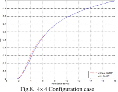
Fig.8. 4 4 Configuration case
Fig. 8 compares the rate geometries with and without CoMP transmissions for 4 4 antennas. As it can be seen, there is slight improvement in the cell average throughput. However, more improvement is observed for the 5% cell throughput.
The multi-user beamforming algorithm [1] of cell, which is based on SLNR, can be easily extended to the multicell system as described below:
2
2 0
2
H M
M H
k k F
k K
n i k
i k
F
SLNR N
Fig.9. Throughput comparison between SLNR multicell and proposed scheme.
Fig.9 compares between SLNR multicell and proposed
scheme. From Fig. 9, the proposed scheme doesn’t
improve average throughput distinctly at the low SNRs, its throughput is much higher than SLNR-multicell at the high SNRs, because the BSs choose the better quality channels for users, so the channels, which leak the least signal power into the other users difficultly, offer high quality service to target user when SNR increase.
VI. C
ONCLUSIONIn this paper, we proposed an enhancement to block diagonalization that uses information about the CCI covariance matrix for each user to improve the sum rate. Numerical examples verified that the proposed MIMO-BD provides the better sum rate performance than the conventional BD [20]. The optimal BD precoding vectors for each user are shown to be in general non-orthogonal, which differs from the conventional orthogonal precoder design for the sum-power constraint case. The simulation results have shown that the proposed scheme shows a much higher performance gain even outperforms zero-forcing scheme in CoMP-JP mode. The CoMP-CBF mode has started to attract much attention for future research work because of the low overhead and good performance. We also shown the downlink coordinated beamforming of CoMP and proposed scheme based on SLNR & SNR to choose the optimal beamforming vector from codebook [21]. The analysis results also show that QR decomposition algorithm reduces the complexity to 60% of the conventional BD method.
R
EFERENCES[1] M. Sadek, A. Tarighat, A. H. Sayed, “A Leakage-Based
Precoding Scheme for Downlink Multi-User MIMO Channels”,
IEEE Trans. Wireless Communication, vol. 6, no. 5, May 2007.
0 5 10 15
0 0.5 1 1.5 2 2.5 3
SNR[dB]
Th
ro
ug
hp
ut
(b
ps
/H
z)
[2] Yong Soo Cho, J. Kim, W. Y. Yang, C. G. Kang, MIMO-OFDM wireless Communications with Matlab, John Wiley & Sons (Asia) Pte Ltd.
[3] L. U. Choi and R. D. Murch, “A transmit preprocessing
technique for multiuser MIMO systems using a decomposition
approach,”IEEE Trans. on Wireless Communication, vol. 3, no.
1, pp. 20–24, 2004.
[4] F. Wang, M. E. Bialkowski,“Performance of block
diagonalization scheme for downlink multiuser MIMO system
with estimated channel state information”,International Journal Communications, Network and System Sciences, vol. 4, pp. 82-87, 2011.
[5] N. Ravindran, N. Jindal, “Limited feedback-based block
diagonal-ization for the MIMO broadcast channel”, IEEE
Journal Selected Areas in Communication, vol. 26, no. 8, Oct. 2008.
[6] F. Wang and M. E. Bialkowski, “Performance of block
diagonalization broadcasting scheme for multiuser MIMO system operating in presence of spatial correlation and mutual
coupling,” International Journal Communication, Network and System Sciences, vol. 3, no. 3, March 2010, pp. 266-272. [7] Q. H. Spencer, A. Lee Swindlehurst, M. Haardt, “Zero-forcing
methods for downlink spatial multiplexing in multiuser MIMO
channels”, IEEE Trans. Signal Process., vol. 52,no. 2, Feb. 2004.
[8] E. G. Larsson and P. Stoica, Space-Time Block Coding for
Wireless Communications, Cambridge University Press, U.K., 2003.
[9] N. Jindal, “MIMO Broadcast Channels with Finite Rate
Feedback,” IEEE Trans. Inform. Theory, vol. 52, no. 11, pp.
5045–5059, 2006.
[10] T. Yoo and A. Goldsmith, “On the optimality of multi-antenna
broadcast scheduling using zero-forcing beamforming,” IEEE
Journal Select. Areas Communication, vol. 24, no. 3, pp. 528–
541, Mar. 2006.
[11] J. Park, B. Lee, B. Shim, “A MMSE vector precoding with block diagonalization for multiuser MIMO downlink”, accepted
at IEEE Trans. on Communications, 2011.
[12] 3GPP, R I-090028, "Leakage-based precoding for CoMP in
LTE-A," Mitsubishi Electric, Jan. 12-16, 2009.
[13] H. Zhang, N. B. Mehta, A. F. Molisch, J. Zhang, and H.
Dai,"Asynchronous Interference mitigation in Cooperative Base Station Systems," IEEE Trans. Wireless Commun., vol. 7, no. I, pp. 155-164, Jan. 2008.
[14] 3GPP, R I-093273, "SRS feedback mechanism based CoMP
schemes in TD-L TE-Advanced," CMCC, Aug. 24-28, 2009.
[15] 3GPP, R I-092585, "Analysis of Feedback Mechanisms for
CoMP," InterDigital, Jun. 29-Jul. 3, 2009.
[16] 3GPP, R I-090028, "Leakage-based precoding for CoMP in
LTE-A," Mitsubishi Electric, Jan. 12-16, 2009.
[17] L. Qiang, Y. Yang, F. Shu, W. Gang, “Coordinated Beamforming in Downlink CoMP Transmission System” 2010 5th International ICST Conference on Communications and Networking, China, 2010.
[18] Z. Huang, B. Li, M. Liu, “Coordinated Beamforming of CoMP with limited feedback”, 2011 International Conference on Network Computing and Information Security, DC, USA, 2011. [19] L. Qiang, Y. Yang, F. Shu, “Zero-forcing beamforming with
limited feedback in coordinated multi-point transmission”, 6th
International wireless communication networking and mobile computing, Chengdu, China, 2010.
[20] S. Shin, J. S. Kwak, R. W. Heath, J. G. Andrews, “Block
Diagonalization for Multi-user MIMO with Other-cell
Interference”,IEEE Trans. on Wireless Communications. [21] Z. Huang, B. Li, M. Liu, “Coordinated Beamforming of CoMP
with limited feedback”, 2011 International Conference on Network Computing and Information Security, DC, USA, 2011. [22] M. Hashem Ali Khan, M. H. Lee, “Zero-forcing Based Multiuser
Beamforming for Coordinated Multi-point Transmission” 12th
International Symposium Communications and Information Technologies (ISCIT 2012), Gold Coast, Australia, Oct. 2-5, 2012.
[23] M. Hashem Ali Khan, M. H. Lee, “Zero-Forcing Beamforming with Block Diagonalization Scheme for Coordinated Multi-point
Transmission”,The 18th Asia-Pacific Conference on
Communications (APCC), Oct. 15-17, 2012, Ramada Plaza Jeju Hotel, Jeju Island, Korea.
[24] Z. Shen, R. Chen, J. G. Andrews, R. W. Heath, Jr., and B. L.
Evans, “Low complexity user selection algorithms for multiuser
MIMO systems with block diagonalization,”IEEE Trans. Signal
Processing, vol. 54, no. 9, pp. 3658-3663, Sept. 2006.
A
UTHOR’
SP
ROFILEMd. Hashem Ali Khan
received his B.S. (Hons.) and M.S. degree in Applied
Physics, Electronics, and Communication
Engineering from Islamic University in Bangladesh in 2003 and 2004, respectively. He is currently doing research towards Ph.D. degree of Electronic Engineering as a researcher at the Institute of Information and Communication in Chonbuk National University, Republic of Korea, since 2009. His current research areas are MIMO, OFDM, and Jacket Matrices.
Moon Ho Lee
is a professor and former chair of the Department of Electronics Engineering in Chonbuk National University, Korea. He received the Ph.D. degree from Chonnam National University, Korea in 1984, and from the University of Tokyo, Japan in 1990, both Electrical Engineering, He was in University of Minnesota, U.S.A, from 1985 to 1986 as a post-doctor. He has been working in Namyang MBC broadcasting with chief engineer from 1970 to 1980, after then he joined to Chonbuk National University as a Professor. Dr. Lee has made significant original contributions in the areas of mobile communication code design, channel coding, and multi-dimensional source and channel coding. He has authored 34 books, 155 SCI papers in international journals, and 240 papers in domestic journals, and delivered 350 papers at international conferences. Dr. Lee is a member of the National Academy of Engineering in Korea and a Foreign Fellow of the Bulgaria Academy of Sciences. He is the inventor of Jacket matrix and it in Wikipedia was cited over 65,363 times, July 20, 2012
Mumta Hena Mustary
received her B.S. degree in Physics from University of Dhaka, Bangladesh in 2009. She is currently a Masters student of Semiconductor and Chemical Engineering at the Institute of Semiconductor
Physics Research Centre, Chonbuk National
University, Republic of Korea, since 2011. Her current research interests include the electrical and optical characteristic of the GaN-based Light Emitting Diode.