Publisher: Centre of Excellence for Scientific & Research Journalism, COES&RJ LLC Online Publication Date: 1st January 2016
Online Issue: Volume 5, Number 1, January 2016 http://www.centreofexcellence.net/J/JSS/JSS Mainpage.htm
Proactive Driver Alert System (PDAS) for Drowsy Drivers
Ramzi Saifan
Dept. Computer Engineering University of Jordan Amman, Jordan 11942
Abstract:
Vehicle drivers lose their focus when fall sleepy which causes very dangerous accidents because the drivers do not even try to avoid the accident. In many cases, these accidents are killing. Therefore, many automobile companies tried to help in detecting drowsy drivers and alert them before they commit accidents. In this paper, we are going to develop a Drowsy Driver Safety System prototype to watch the driver, and generate an audio alarm when the driver is detected as drowsy. This audio alarm helps keeping the driver in contact to avoid any consequences.
There exist several drowsy detection systems. Most of them focus on detecting drowsiness using techniques such as steering behavior, lane tracking, eye detection, yawning state or a combination of them. In this paper, we also track the driver eye which is similar to some others. But, we are suggesting new techniques like driver’s hand tension, which is also a considerable feature for drowsiness detection. We also use a supplementary technique based on the relationship between the speed and the drift angle of the car to detect drowsy divers.
Keywords:
Drowsy driver, driver sleepiness, Drowsy driver safety system prototype
Citation:
1.INTRODUCTION
When driving the car alone at late night, and after a long work day or in the afternoon at the nap time, the driver eyes become heavy and yawning becomes almost constant. The driver starts closing the eyes frequently for half a second or a second. But rapidly, the driver starts closing eyes for longer periods where falls in sleep. Fortunately, this time the driver waked up when another driver in another car warned him before make an accident. This time the driver was lucky; next time, nobody knows, it can be a tragedy end of life.
Drowsiness is the state of being sleepy or about to sleep, which is the cause of many accidents in the world. It is really difficult to prevent this type of accidents without a real system to follow up the driver state and report or make action if the driver was detected sleepy.
The statistics show high ratio of deaths as a result of driver drowsiness (more details in Section 2). This happens because the driver in this state cannot avoid or attempt to avoid the accident. There is no breaking action, and the vehicle is out of order. Many attempts were done to develop new systems to avoid this situation and take an action in order to keep the driver awake. But many of these works are characterized by their complexity and high cost, which is considered as a considerable drawback of these systems.
Developing a system for detecting and preventing driver’s drowsiness state is considered a challenge in the field of accidents avoiding. This is due to the big contribution of drowsiness on the percentage of the overall number of accidents in the world.
In fact, there is more than one method to detect the drowsiness behavior: lane monitoring [1], steering monitoring, and eye status monitoring. Lane monitoring does not succeed all the times. Roads in many countries do not have the lanes system which impacts the lane monitoring system performance. Also, the response time of lane monitoring will be a little late, because it warns the driver in the wasted time after may be making an accident.
The second approach is steering monitoring [2]. Typically, drivers are constantly judging the situation ahead and applying small, smooth steering adjustments to correct for road angles by turning the steering wheel in small increments. Steering wheel metrics have been suggested to measure steering behavior from standard deviation of steering wheel angle and steering wheel velocity. But, what if the driver decided to take a sharp exit to the left or to the right? In this case, it will be mistakenly characterized as a drowsy driver. The Third approach is eye status monitoring. This approach has advantage over the other approaches because it depends on the driver state not on the car state. This approach is faster in notifying the driver to wake up, because the aspects of drowsiness appear earlier on driver’s eyes than on driver’s actions.
44
PDAS (Proactive Driver Alert System) is a new system which tries to solve drowsiness driver problem. The main contribution of PDAS is the addition of new approaches in detecting drowsiness. PDAS depends on more credible aspect, which is the driver himself. We are going to build an alert system that takes into consideration driver’s eyes status combined with the hand grip tension to tell whether the driver is drowsy or not. We also adopt an alternative method which is based on the speed of the car and the angle of drift from the path. Tracking the driver’s behavior is more efficient than tracking car behavior and faster, where time is critical for these systems.
The remaining of this paper is organized as follows: Section 2 shows background information and drowsiness related statistics, while Section 3 shows some related works in the same field. Section 4 provides the detailed system design and components. Results and implementation will be discussed in Section 5. Finally we conclude in Section 6.
2.BACKGROUND AND STATISTICS
Drowsy driving occurs too often. The U.S National Highway Traffic Safety Administration (NHTSA) reports that drowsy driving causes more than 100,000 crashes a year. These accidents result in an around 40,000 injuries and 1,550 deaths [3]. In reality, numbers could be higher because there is no “breathalyzer” test for drowsiness where these numbers are based on drivers’ avowals.
In 2002 The Gallup Organization surveyed more than 4,000 drivers in the U.S. [4]. Survey results showed that 37 percent of drivers reported falling asleep at least once while driving. Males were almost twice as likely as females to report that they had driven drowsy. Gallup estimated that 7.5 million drivers had nodded off while driving in the previous month.
Virginia Tech Transportation Institute [5] installed video cameras and sensors in 100 vehicles that were driven by ordinary people every day for one year. The study gathered nearly 2 million miles of real world driving data. It was found that driver drowsiness was a contributing factor in at least 20 percent of all crashes. The researchers estimated that you are four to six times more likely to have a crash or near crash when you are driving drowsy [5].
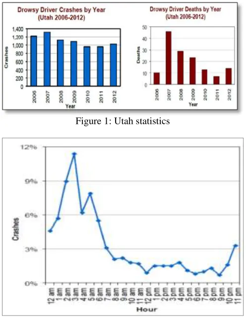
Figure 1: Utah statistics
Figure 2: Percent of total crashes per time of the day.
Anyone who doesn’t get enough sleep can drive drowsy. But certain people have a higher risk than others, including people who: 1) take medications that cause sleepiness, 2) drivers who drink alcohol, 3) drivers who work night shifts or rotating shifts, 4) drivers who have a sleep disorder, 5) young male drivers, and 6) drivers who regularly don't get enough sleep .
Data shows that most crashes caused by drowsy driving occur from midnight to 8:00 a.m. It is most natural for the body to go to sleep when it is dark outside. This is why it is so hard for drivers to fight off sleep at night. On the other hand, too many people tend to have a nap time in the afternoon. Therefore, those drivers may fall asleep if they drive at that time. This is why drowsy driving is a cause of many accidents from 1:00 p.m. to 3:00 p.m. At both of these times of day, the body gets sleepy even when it is well rested [6].
In another study, 82% of drowsy-driving crashes involved someone driving alone [7]. A driver’s company can help in keeping the driver alert. On the other hand, drowsy drivers do not try to avoid the accident where the driver never hit the brakes before the accident [7]. This leads to more sever accidents and more deaths out of these accidents.
3.RELATED WORK
46
detect driver drowsiness. Moreover, some of them depend on human behavior, and others depend on car behavior. Some of the major automobiles brands which use drowsy driver detection system are Mercedes Benz, Volvo, Audi, Volkswagen, and BMW [5]
Mercedes-Benz Company developed a system called “Attention-Assist System” [16]. The system was fitted as standard in the new E-Class and the model year 2009 S-Class. The idea behind this system is to detect steering behavior in the first few minutes of the trip. Using this behavior the system makes a profile for this driver, and then starts comparing the current steering behavior of the driver by this profile. When the driver makes a sharp transition from a state to another in the steering behavior curve that makes a real difference from steering profile (this difference says that the driver is in drowsy state and needs a wakeup call), then the system warns the driver by emitting an audible signal and flashing up an unequivocal instruction on the display. The main disadvantage of this system is relying on one technique which is the driver’s handling of the steering wheel which could be different from one to another.
Toyota developed their Driver Monitoring System in 2006 for the latest Lexus models. They use a camera mounted on top of the steering. It monitors the exact position and angle of the driver’s head while the vehicle is in motion. The system can briefly apply the brakes to alert the driver [17]. Toyota System can detect if drivers become sleepy by monitoring their eyelids. Their solution combines driver face orientation and eyelid activity to identify drowsiness.
The authors in [18] use four factors to state drowsiness state: duration of eye closure, frequency of eye blinks, detection of yawning, and head rotation. Similarly, the authors in [19] adopted eye state and yawning state for detecting drowsy drivers.
4.SYSTEM OVERVIEW
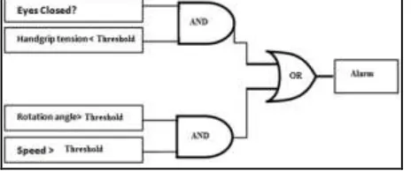
There are two techniques in the system. If any of these happened, it triggers an alarm to the driver. The first technique depends on the driver, the inputs to it are:
1.A camera which detects the eye state (open or close).
2.The force sensor which is based on the hand grip tension applied by the driver on the steering wheel.
The second technique depends totally on car status where the inputs to it are: 1.The speed of the car
2.The heading angle of the car.
As Figure 3 shows, an OR function links these two techniques which will build more robust and safe system to achieve the main goal of the system.
4.1.Eye State Detection Technique
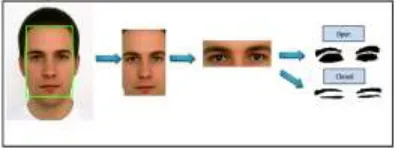
The first step for eye state detection is face detection. Its main advantage is decreasing search space. Identifying and locating human faces in images is considered a big constraint in complex images with complex background. However in our case, the driver background is usually uniform. It is good to start making use of this point. It is easy now to isolate the face from its surrounding background. This can be done by using multi block local binary pattern algorithm [8]. This algorithm extracts the features of the face from the image and compares it with a model contains standard features of the face.
Once the face was isolated from the image, we use skin segmentation algorithm [9] to extract eyes status. The main job of this algorithm is to detect the skin part of the image. Comparing the skin ratio of the eye lid when the eye is closed or open will vary accordingly, and from this we can judge the status of the driver’s eye as shown in Figure 4.
Figure 4: Eye state detection
4.2.Hand Tension Technique
The output of this phase helps us to determine driver’s status which will be combined using an “AND” function with the output of eye status. If both parts are positive (i.e., drowsy eyes and small tension), then the driver is drowsy.
For this purpose we use a force sensing resistor which exhibits a decrease in resistance with the increase of the force applied to the active surface of the sensor. Using this relation, we extract the force applied. If the force applied is less than a predetermined threshold value, combined with eye detection output, we can conclude that the driver is not only closing eyes, but also is not controlling the steering wheel which will be a definite indication that the driver is in drowsiness state and needs to be alerted.
4.3.Vehicle Monitoring
The Eye state detection and hand tension technique depend on the driver physical state. However, it is more sensible to have another input to the system which is based on analyzing the vehicle status. Adding this part which depends on the vehicle monitoring will result in more robust system with safer design for alerting the driver.
The core task of this part is to detect if the driver started to make a sharp turn while driving on high speed. This could be due to drowsiness or unsafe driving where in both cases the driver should be alerted. This can be implemented using an electronic compass that will provide the heading angle with respect to magnetic north and by continuous calculation of the difference between the current angle and the previous value. If the difference in degrees is higher than specific threshold (e.g., 10 degrees), and if the speed is higher than specific threshold (e.g., 60), then we can conclude that vehicle is out of control and the driver needs to be alerted.
48
4.4.System Design
An effective proactive driver alert system (PDAS) must follow general rules including: a non-intrusive monitoring system that will not distract the driver, a real time monitoring system because time is critical in such systems, and adaptability to day time (daytime and nighttime), road types (has lanes or not), and type of car (luxury or old).
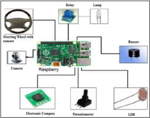
PDAS components are shown in Figure 5. It is composed of: a microcontroller Raspberry kit, a camera, a steering wheel with force sensors connected to the Raspberry kit for taking the decision of the first part. Also it contains an electronic compass with a potentiometer which simulates the speedometer in the cars connected also to the Raspberry. An LDR (light dependent resistor) with relay and lamp are used also to help with discovering the face of the driver when the light is not enough to show the face details.
Figure 5: Overall system components of PDAS
4.5.System Algorithms
As mentioned previously, first part that is responsible for detecting the eye state consists of two main steps: face detection and eye status detection. In each of the following subsections we discuss the algorithm that we have chosen to be implemented in our project for each step.
4.5.1.Face Detection Algorithm
We have used multi block local binary pattern (MB-LBP) algorithm. In order to understand the way the algorithm works we need to know about the local binary pattern (LBP) at first.
Figure 6: LBP
The LBP only supports small area and the bitwise comparison between two pixels is much affected by noise. Moreover, the features calculated in local 3x3 neighborhoods cannot capture large structure such as face, for that reason the multi block LBP (MB-LBP) is used [11].
4.5.2.Multi Block Local Binary Pattern (MB-LBP)
MB-LBP is an extension to the basic LBP, with respect to neighborhoods of different sizes. Comparisons between single pixels in LBP is simply replaced with comparison between average of intensities of sub-regions, it is done by comparing the central rectangle average intensity (gc) with its neighborhood rectangle (g0...g8).
The output gives of (MB-LBP) a binary sequence which expresses the feature from the image as follow:
Where gc is the average intensity of the center pixel, and gi (i= 0...8) the neighborhood pixels. S is given by the following equation:
(2)
We use the resulting binary pattern as the feature value of MB-LBP, such a pattern can be used to detect different elements in the image such as edge, lines, flat area and corner.... etc. MB-LBP can be computed very efficiently using integral image.
The output according to MB-LBP implementation is too large set of features, hence the features set must be restricted to small number of features. Therefore, here we must design a classifier to extract the face feature.
AdaBoost learning [12] helps to select the best LBP-sub window histogram feature and construct the face classifiers. It helps in learning effective feature form large ones, then a weak classifier from the selected feature is designed. After that, the weak classifier is combined to extract a strong one, hence the face feature is extracted. Weak learner property is used when the improvement on the set of features is very small; by using the AdaBoost algorithm the performance of face detection is increased. The following equation shows how the strong classifier extracted from combining the weak ones
50
Where F(x) is a strong classifier and fm(x) is a weak classifier. It is important to define a weak classifier to be the threshold classification function that the AdaBoost algorithm starts with.
Eye detection using MB-LBP starts with computing the integral image which is the sum of all pixels from top-left corner to each pixel in the image. After that, a LBP is calculated followed by dividing the image into sub-windows, a MB-LBP and histogram is computed for each sub-window, the histogram gives information about the distribution of MB-LBP feature over the whole image. Actually, these MB-LBP features are used to extract any feature of the human face, such as human eyes, nose, and mouth. In fact, each feature needs a reasonable dataset to be correctly detected.
After the previous steps, the overlapped detections are compared with a model for the face feature then threshold the detection based on number of features.
Eye State Detection Algorithm
The step that follows the detection of the driver’s face is to detect eyes then determine the states of the eyes whether it is open or close. The eye detection approach done by using an algorithm called skin color segmentation [9]. Skin detection is the process of finding skin-colored pixels in an image. It typically transforms a given pixel into an appropriate color space, and then it uses a skin classifier to determine the pixel whether it is a skin or a non-skin pixel, based on a specified database of non-skin colored pixels.
There are two ways of segmenting the image based on skin color: converting the RGB picture to YCbCr space or to HSV space. YCbCr space segments the image into luminance components and color components, while HSV method segments the image into three components: hue, saturation, and value. In our paper, we choose to convert to YCbCr space. This can be done using the following equations [13]:
[R G B]=[γ Cb Cr] [ ■(1&1&1@0&-0.344&[email protected]&-0.714&0.0) ]
[γ Cb Cr]=[R G B] [ ■(0.299&-0.168935&[email protected]&-0.331665&[email protected]&0.50059&-0.081282) ]
The main advantage of converting the image into YCbCr is removing luminance components during image processing. In the RGB each component of the picture has a different brightness, in YCbCr all information about the brightness is given by Y component, while Cb (blue) and Cr (red) give a good indication whether a pixel is a part of skin or not [13]. This is depending on the strong correlation between the Cb and Cr.
System Hardware
Control Unit: Many embedded microcontrollers could be used in this place such as Raspberry board [14] and Intel Galileo [15], where both act as single board computers. In this part we will discuss the controlling elements in the system. The controlling element we have is the Raspberry board that takes the power from the car and performs the required operations. The board performs all the required processing includes: receiving the images from the camera, applying face detection, eye state detection, getting the result of the pressure sensor readings, getting the car heading angle from the compass, getting the speed value from the potentiometer and making the decision from those values if the driver is drowsy or not and if he/she has a full control over the car or not, and then notifying the driver by the alarm.
Camera: we used a camera with 2.0 megapixel resolutions. This camera is sufficient to do the job.
Light Dependant Resistor (LDR): PDAS uses light sensor to detect the light condition (dark or not). The reason behind using it is to solve illumination problems. It is connected directly to the control unit (Raspberry), and is placed in front of the camera. If any poor illumination is detected, then the control unit sends a signal to turn the lamp on. When PDAS detects bad light conditions, then it uses the 12V lamp to improve the light. Relay: A relay is an electromagnetic switch. It is activated when a current is applied to it. The maximum voltage gets out of the Raspberry kit is 5V. Therefore, we need the relay to separate high power circuit (lamp requires 12 V) from the low power one (Raspberry 5V circuit).
Force Sensing Resistor (FSR): is a polymer thick film (PTF) device which exhibits a decrease in resistance with an increase in the force applied to its active surface. The active area of this sensor responds to the amount of force on it, and its resistance then will be changed, these values of change can be converted to a voltage if we connect a resistor in series with the sensor and send this voltage to the Raspberry. The circuit for FSR in PDAS is shown in Figure 7.
Figure 7: FSR circuit
Potentiometer: this device simulates the speedometer in the car, which will help us virtually to indicate if the speed is high or low, the potentiometer that we have used gives a range of resistor values within the domain of (1-470) KΩ, and it’s connected directly to the Raspberry. Any change in the resistance value of the potentiometer is considered as a change in the speed. In reality this value will be taken directly from the speedometer but for demonstration purposes we used the potentiometer.
52
5.IMPLEMENTATION AND RESULTS
We used Matlab toolbox for image acquisition. It enables us to acquire images and videos form cameras directly into Matlab. Whenever the PDAS is working, a video camera will be turned on, and it will continuously take pictures for the driver from the installed camera. Matlab image acquisition toolbox and image processing toolbox provide a complete environment for implementing the (MB-LBP) algorithm in such a good way.
To do face detection, we used MP-LBP algorithm that is implemented in the toolbox. It outputs a 5xN matrix where the N is the number of detected faces in the image and it gives five corresponding parameters for each of the detected faces. The five parameters are: x and y location, width, number of features, and their detection value. Then, we plot a rectangle around the face that has enough number of face features, and has the maximum width (since the driver face is the closest to the camera), using its x-y coordinates.
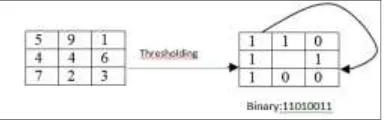
After the face of the driver has been detected, the image of the face is transferred to YCbCr space and based on some calculations using the mean and the standard deviation of skin’s color, the minimum and the maximum of the cb and cr are calculated using the equations below, to use them in thresholding the pixels where the skin is presented.
After calculating these equations, we obtain skin distribution of the image by comparing the pixels in the YCbCr image with the resultant values. An image of the driver’s eyes has a value of one where the skin is placed and zero in the place that does not contain a skin.
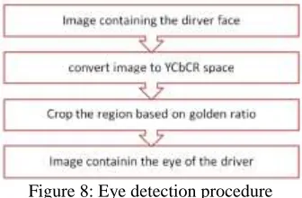
Binary image enhancement is the next step to reduce background and remove holes within the image. The overall procedure is shown in the flow chart shown in Figure 8.
Figure 8: Eye detection procedure
By implementing the above procedure, an image containing the driver’s eyes is the output. Next, we will detect the state of the eyes (open or closed). First we assume that the percentage of white to black in open eyes is 0.5, after that we obtain this ratio 15 times and then find the average ratio between these values. After 15 times the output will be the average ratio of the white to black for the driver (where white pixels represent the skin and the black represents the non-skin ones). This provides us with reference value to compare the continuously taken images of driver with it. Comparing the new ratio with the
reference value will result as follows: if the ratio is bigger, then the eyes are closed. Otherwise, the eyes are open.
There are force sensors planted around the steering. For testing purposes, only two force sensors are used. These sensors are connected directly to the Raspberry board and they respond to the amount of force on them.
Figure 9 shows results of the face detection. The face is detected inside the green rectangle. In fact, we used a dataset of 200 images for this test case. After analyzing the results, we found a misdetection in 33 images. This means that the error is 16.5%.
Figure 9: Face detection results
Figure 10 shows some results of eye detection. The figure that shows more whiteness is considered as closed eyes since the white pixel is a skin. On the other hand, the figure with more blackness is open eyes. The dataset used in this stage contains 100 images. After analyzing these images, we found misdetection in 19 images. That is, there is an error rate of 19%.
Figure 10: Eye status detection results
To test the handgrip part, we have simulated 50 measurements for the sensor. 25 of them are for awake people while the others are for sleepy people. Table 1 shows samples of these measurements. As we can see, in general, the awake people hand tension measures are less than that for the sleepy people. Therefore, this gives a good impression that the driver is sleepy. But, the audio alarm will not start for this value except if the driver rotated fast on high speed.
Table 1: Hand tension measures
Awake person Sleepy person
503 985
728 1002
626 969
54
when we rotate the car slowly, there is no alarm. Also, if the car speed represented by the potentiometer is small, whatever the rotation angle, there is no alarm. We got the alarm when the potentiometer is representing high speeds and the rotation done very fast.
1.CONCLUSION
In our system we have solved the drowsiness problem for the driver using an image processing approach for the driver’s eyes. When the driver feels drowsy, his/her eyes start to close. Therefore, our approach is to detect when the eyes of the driver are closed or are nearly closed. Also, our System depends on another driver behavior that is the handgrip strength. A third approach that makes the project more robust and safe to achieve the main goal of the system is measuring the heading angle against the speed of the car to detect if the driver is making a turn with a high speed.
7. References
[1]Friedrichs, Fabian, and Bin Yang. "Drowsiness monitoring by steering and lane data based features under real driving conditions." Proceedings of the European Signal Processing
Conference, Aalborg, Denmark. Vol. 2327. 2010.
[2]Krajewski, Jarek, Martin Golz, and David Sommer. "Detecting sleepy drivers by pattern recognition based analysis of steering wheel behaviour." Der Mensch im Mittelpunkt
technischer Systeme (2009): 288-291.
[3]Drobnich, Darrel. "A National Sleep Foundation's Conference summary: the National Summit to Prevent Drowsy Driving and a new call to action." Industrial health 43.1 (2005): 197-200.
[4]Royal, Dawn. National survey of distracted and drowsy driving attitudes and behaviors:
2002: volume 1: findings report. No. DOT HS 809 566. 2003.
[5]Neale, Vicki L., et al. "An overview of the 100-car naturalistic study and findings." National
Highway Traffic Safety Administration, Paper 05-0400 (2005).
[6]Young, Hunter T. "A Safety Analysis of Fatigue and Drowsy Driving in the State of Utah." (2007).
[7][32] UCLA Sleep Disorders Center, 1990-2015. http://sleepcenter.ucla.edu/body.cfm?id=56 [8]Ojala, Timo, Matti Pietikäinen, and David Harwood. "A comparative study of texture
measures with classification based on featured distributions." Pattern recognition 29.1 (1996): 51-59.
[9]Phung, Son Lam, Abdesselam Bouzerdoum, and Douglas Chai. "Skin segmentation using color pixel classification: analysis and comparison."Pattern Analysis and Machine
Intelligence, IEEE Transactions on 27.1 (2005): 148-154.
[10]Guo, Zhenhua, Lei Zhang, and David Zhang. "A completed modeling of local binary pattern operator for texture classification." Image Processing, IEEE Transactions on 19.6 (2010): 1657-1663.
[11]Liao, Shengcai, et al. "Learning multi-scale block local binary patterns for face recognition." Advances in Biometrics. Springer Berlin Heidelberg, 2007. 828-837. [12]Freund, Yoav, and Robert E. Schapire. "A decision-theoretic generalization of on-line
learning and an application to boosting." Journal of computer and system sciences 55.1 (1997): 119-139.
[13]Ghazali, Kamarul Hawari Bin, Jie Ma, and Rui Xiao. "An Innovative Face Detection Based on YCgCr Color Space." Physics Procedia 25 (2012): 2116-2124.
[14]Upton, Eben, and Gareth Halfacree. Raspberry Pi user guide. John Wiley & Sons, 2014. [15]Ramon, Manoel Carlos. Intel Galileo and Intel Galileo Gen 2. Apress, 2014.
[16]Mercedes-Benz TecDay Special Feature: Attention Assist, Blind Spot Assist And Distronic
Plus / Brake Assist PLUS: http://www. emercedesbenz.
com/Nov08/12_001506_Mercedes_Benz_TecDay_Special_Feature_Attention_Assist_Bli nd_Spot_Assist_And_Distronic_Plus_Brake_Assist_Plus. html
[17][Online]:www.testdriven.co.uk/lexus-ls-600h
Gupta, Sheifali, and Er Garima. "Road Accident Prevention System Using Driver’s Drowsiness Detection by Combining Eye Closure and Yawning."International Journal of Research1.6 (2014): 839-842.