© Shiraz University
A COMPLETE PROCEDURE TO DETERMINE EARTH FAULT CURRENT
DISTRIBUTION AND SPLIT FACTOR FOR GROUNDING
GRID DESIGN OF HV SUBSTATIONS
*N. RAMEZANI AND S. M. SHAHRTASH
* *Center of Excellence for Power System Automation and Operation, Department of Electrical Engineering, Iran University of Science and Technology (IUST), Tehran, I. R. of Iran,
Email: [email protected]
Abstract– To design a safe substation grounding grid, it is necessary to compute the split factor for earth fault current and also current distribution in other possible paths. In this paper, a novel, simple and accurate method is developed for determination of this factor. In the proposed algorithm grounding grid impedance of adjacent substations, dissimilar tower footing resistances, different parallel circuits, more than one earth wires and different spans in transmission lines can be considered. In addition, the formulation for the earth faults through line towers is presented. Finally, the results are compared with the addressed cases that are comparable and show good agreement and accuracy.
Keywords– Split factor, earth fault current, touch and step voltages, grounding grid design, HV substations 1. INTRODUCTION
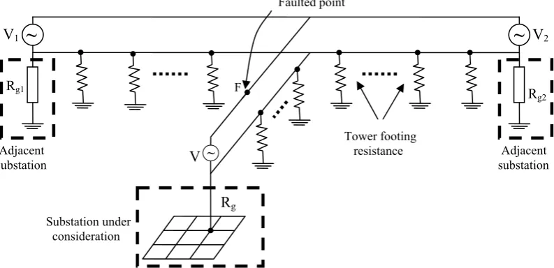
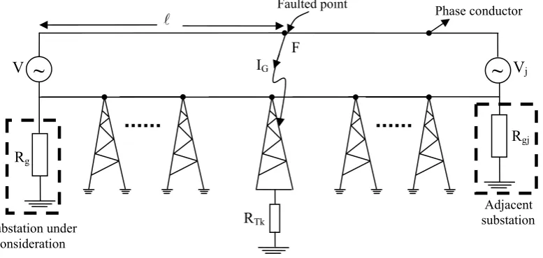
The earth fault currents in a power system circulate through transmission line earth wires, tower footing resistances, substation grounding grids and phase conductors connected to a faulted point as shown in Fig. 1.
To design a safe substation grounding grid and prevent any over-design, it is of prime importance to compute, correctly the split factor of an earth fault, and also current distribution in other possible paths by modeling overhead lines and adjacent substation grounding grids.
The existing grounding standard for safety in AC Substation grounding such as ANSI/ IEEE Std 80-2000[1] does not provide a direct approach for the determination of the split factor for systems with the following conditions:
a. Different length of spans in incoming/outgoing lines, b. Different tower footing resistances,
c. Existence of disjointed earth wires.
Along with these conditions, different methods have been introduced to determine this factor. Some have made different approximations and simplifications [2-6], while others have been recorded as analytical methods [7-11]. In general, the ability of methods to consider the contribution of the following parameters in a simple way may be proposed as appropriate criteria for evaluating their performances:
-Mutual inductances between phase conductors and earth wires, -Different spans of incoming/outgoing overhead lines,
-Different tower footing resistances,
-More than one earth wire, either fully connected or disjointed,
Rg2
Adjacent substation
-Fault location, either inside or outside the substation,
-Earth fault through short circuit to a tower of an overhead line, -Large and complicated power system.
It can be stated that none of the methods presented can include all of the above mentioned parameters. In this paper, a novel, simple and accurate method is developed for the determination of the split factor of earth fault current, where all of the above-mentioned parameters can be considered. Accordingly, the complete formulation for general cases; first for line-to-earth short circuits inside and then outside the substation and also through any tower of outgoing overhead transmission lines are presented, and finally the closed form equations for considering special conditions (such as double-circuit lines, multi earth wires and disjointed earth wires) are given. The results for two case studies are given and compared with some previous methods and the accuracy of the proposed method is shown.
Fig. 1. The power network configuration (only the faulted phase conductor is shown) 2. MAIN PARAMETERS IN THE MODEL
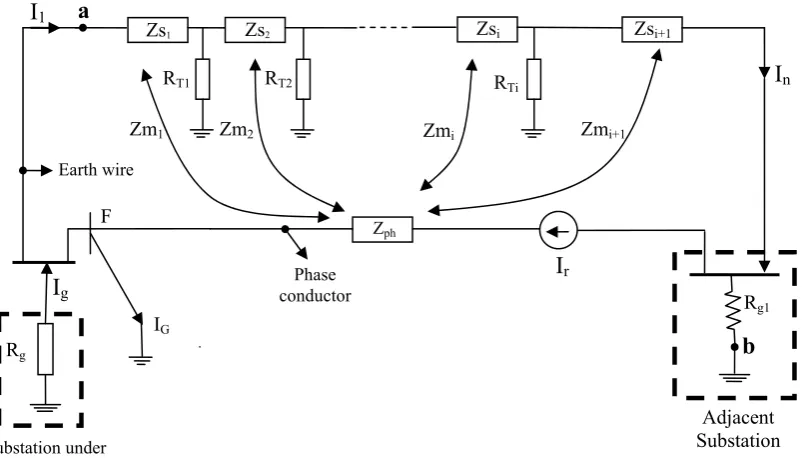
A network containing two substations and a transmission line in-between is shown in Fig. 2, where Ig is
the portion of the earth fault current passing through the substation under consideration, I1 is the section of
Ig which flows through the earth wires and In is the outgoing current from earth wires.To determine split
factor for an earth fault occurring at point F in the vicinity of the substation under consideration, different components of the mentioned network should be modeled as in the following steps. The modeling and computation for earth faults located outside the substation on an outgoing overhead line is presented in sections 3.5-b, 3.5-c.
1. Faulted phase conductor is modeled by self impedance of a phase conductor and its mutual impedances with earth wires and a series current source (Ir) which equals to the portion of the fault current
through a phase conductor ( and is calculated by any short circuit program in the power system). Modeling the case of double circuit lines is explained in 3.5.
2. The earth wire(s) and tower footing resistances are represented by a ladder network of impedances and resistances, where the impedance Zsj is the self impedance of i-th span of earth wire according to its
length, and RTj is the footing resistance of i-th tower. The mutual impedance between the phase conductor
and i-th span of earth wire is represented by Zmj .
3. Grounding grid of the substation under consideration is modeled with a resistance Rg.
4. Adjacent substations grounding grids are each modeled with a resistance, e.g. Rgm for m=1,…, n. ~
~ ~
Rg1
V1 V2
Faulted point
Tower footing resistance Adjacent
substation
Rg
V
Substation under consideration
June 2008 Iranian Journal of Science & Technology, Volume 32, Number B3 Fig. 2. Complete model for the network connected to the faulted point inside the
It is not necessary to mention that the earth fault current, ( ) is also calculated through the short circuit
Typical initial equivalent circuit of earth wire(s) and tower footing resistances is shown in Fig. 3 (wit
Fig. 3. Equivalent circui f earth wire(s) and towers
To Adjacent Substation
Z
insubstation (only the faulted phase conductor is shown)
G
I
study of the power system.
3. THE PROPOSED METHOD
In the proposed method, the mutual coupling between the earth wires and phase conductors are waived in the first step and the equivalent circuit of earth wires, tower footing resistances and adjacent substations grounding grid are determined. Then by compensating the effect of those mutual impedances, the fault current distribution among the grounding grid of the substation under consideration and other components of the power system is calculated.
Step by step implementation of this method is as follows:
a) Constructing initial equivalent circuit
hout considering mutual impedances between earth wire and phase conductor). In this circuit the length of spans and, ultimately, their self impedances (Zsj) and tower footing resistances (RTj) may be
different.
t o
put
+
_
V
1Zs
1Zs
2Zs
n+ Zs
n+1_
V
n2 T
R
1 T
R
n T
R
I
1Substation under consideration
Adjacent Substation Zph
Zm2
Zm1 Zmi Zmi+1
Zs1 Zs2 Zsi Zsi+1
I
1I
nEarth wire
RT1 RT2 RTi
Rg1
Rg
I
rF
I
g conductor PhaseIG
a
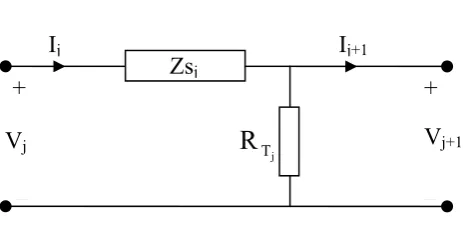
Fig. 4. Equivalent circuit of one span and tower
The overall transfer function of this ladder network can be constructed according to the transmission matrix for a two-port module, as in Fig. 4.
In Fig. 4, the transmission matrix is introduced as:
⎥ ⎥ ⎦ ⎤ ⎢ ⎢ ⎣ ⎡ = ⎥ ⎥ ⎦ ⎤ ⎢ ⎢ ⎣ ⎡ ⎥ ⎥ ⎦ ⎤ ⎢ ⎢ ⎣ ⎡ = ⎥ ⎥ ⎦ ⎤ ⎢ ⎢ ⎣ ⎡ + + + + 1 j 1 j j 1 j 1 j 4 j 3 j 2 j 1 j j j I V . T I V t t t t I V (1) where: 1 t , R 1 t , Z t , R Z 1
t j4
T 3 j sj 2 j Tj sj 1 j j = = = +
= (2)
Consequently, the following relation is used to find the input impedance of the ladder network:
⎥
⎦
⎤
⎢
⎣
⎡
∏
=
⎥
⎦
⎤
⎢
⎣
⎡
⎥
⎦
⎤
⎢
⎣
⎡
=
⎥
⎦
⎤
⎢
⎣
⎡
= n n j n j n nI
V
.
T
I
V
.
T
T
T
T
I
V
1 22 21 12 11 1 1 (3)and the input impedance is:
1 1
input
V
I
Z
=
(4)b) Including adjacent substations grounding grid
In this stage, the contribution of an adjacent substation grounding grid in Fig. 2 is converted as in Fig. 5.
Fig. 5. Combining adjacent substation grounding grid effect with the equivalent circuit Equivalent circuit of
Fig.3
R
gR
g1I
nR
g1R
g1R
g1I
r+ _
+ _
a
b
I
1I
nZ
phI
GI
r Substation under consideration Adjacent SubstationZs
j j TR
I
jI
j+1+
_
+
V
jV
j+1June 2008 Iranian Journal of Science & Technology, Volume 32, Number B3
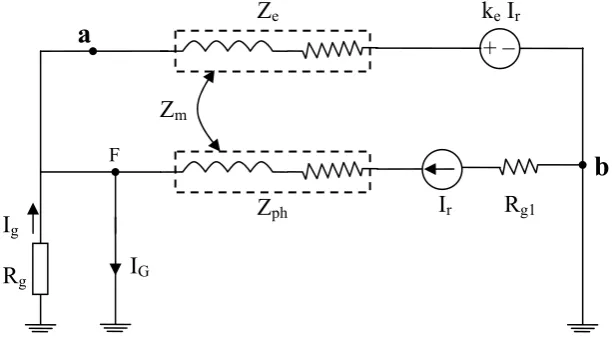
The Thevenin's equivalent circuit, seen between points "a" and "b" in Fig. 5, is shown in Fig. 6 and its parameters are introduced by the following equations:
22 1 g s 21
12 1 g s 11 e
T ) R Z ( T
T ) R Z ( T Z
1 n
1 n
+ +
+ + =
+
+ (5)
22 1 g s 21
1 g 1
g s 22 g s 21
12 1 g s 11 1 g 22 1
g s
1 g 12 e
T ) R Z ( T
R )
R Z ]( T ) R Z ( T [
] T ) R Z ( T [ R T R
Z R T k
1 n 1
n 1
1 n
1 n
1
n + +
− =
+ +
+
+ + −
+ =
= +
+
+ +
(6)
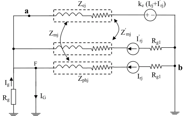
Fig. 6. Thevenin’s equivalent circuit c) The final equivalent circuit
By substituting the equivalent circuit of Fig. 6 and the inclusion of the total mutual impedance between the earth wire(s) and the faulted phase conductor, the final equivalent circuit for the network of Fig. 2 is obtained as shown in Fig. 7.
Fig. 7. The final equivalent circuit with one adjacent substation
Following the same procedure, the equivalent circuit for a substation with N outgoing transmission lines and adjacent substations can be found as shown in Fig. 8. It must be remembered that the fault currents coming through each line (Irj, for the jth transmission line) are computed through short circuit
study.
d) Computing the split factor
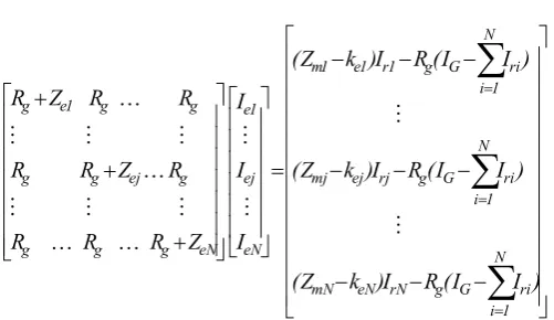
According to Fig. 8, the mesh equations can be realized and introduced in matrix form as:
R
gI
ga
b
Z
mF
a
I
G+
_
R
g1Z
phZ
ek
eI
rI
rZ
eb
k
eI
r⎥ ⎥ ⎥ ⎥ ⎥ ⎥ ⎥ ⎥ ⎥ ⎥ ⎥ ⎥ ⎦ ⎢ ⎢ ⎢ ⎢ ⎢ ⎢ ⎢ ⎢ ⎢ ⎢ ⎢ ⎢ ⎣ − − − − − − − − − = ⎥ ⎥ ⎥ ⎥ ⎥ ⎥ ⎦ ⎤ ⎢ ⎢ ⎢ ⎢ ⎢ ⎢ ⎣ ⎡ ⎥ ⎥ ⎥ ⎥ ⎥ ⎥ ⎥ ⎦ ⎤ ⎢ ⎢ ⎢ ⎢ ⎢ ⎢ ⎢ ⎣ ⎡ + + +
∑
∑
∑
= = = ) I I ( R I ) k Z ( ) I I ( R I ) k Z ( ) I I ( R I ) k Z ( I I I Z R R R R Z R R R R Z R N 1 i ri G g rN eN mN N 1 i ri G g rj ej mj 1 i ri G g 1 r 1 e 1 m eN ej 1 e eN g g g g ej g g g g 1 e g M M M M K K M M M K M M M K (7)where Iej is the part of the fault current through the earth wire of j-th incoming/outgoing transmission line.
Consequently, the split factor (Sf) in the substation under consideration is obtained by:
(
)
fault n 1 j ej rj G fault g fI
I
I
I
I
I
S
∑
=−
−
=
=
(8)where Ifault in the denominator is the same as IG whenever the split factor is computed for an earth fault
outside and/or in the vicinity of the substation. In the case of an earth fault inside the substation under consideration, the same equations are used, provided that IG and Ifault are set to zero and the short circuit
current comes through the faulted transmission line, i.e. Irj, respectively.
Fig. 8. General equivalent circuit e) Special conditions
In addition to the introduced abilities of the proposed method, the following cases can also be analyzed by this procedure through some modifications in Eq. (7).
Substation under consideration
F
R
gI
gI
G+
_
R
g1Z
ph1Z
e1k
eNI
rNI
r1Z
m1+
_
Z
phNZ
eNI
rNZ
mNI
e1I
eNk
e1I
r1June 2008 Iranian Journal of Science & Technology, Volume 32, Number B3
'
Fig. 10. The final equivalent circuit r senting a fault at a distance
1. Existence of double circuit transmission lines: As shown in Fig. 9, Eq. (7) is valid for double circuit transmission lines provided that Irj are substituted by Irj+I'rj, where Irj is the fault current passing through the
first circuit and I'
rj is the fault current coming through the second circuit of the j-th transmission line. This
derivation assumes that the mutual impedances between each one of the circuits and earth wire are identical.
If the assumption of identical mutual impedances between similar phases of double circuit lines with earth wires are not valid or not as accurate as is desired, the j-th element of the right-hand side of Eq. (7) is replaced by:
The j-th element of right-hand side of Eq. (7) = (Z I Z I k (I I )) R (I I ) (9)
N
1 i
ri G
g ' rj rj ej ' rj ' mj rj
mj
∑
= − −
+ −
+
where Zmj, Zmj are the mutual impedances between the first and second circuits of the faulted line with the
earth wires, respectively.
Fig. 9. The final equivalent circuit for double circuit ansmission lines (with one adjacent tr substation)
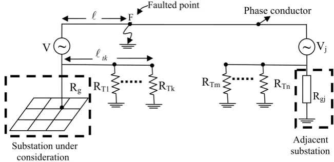
2. Effect of fault location on Sf: Eq. (7) has been derived for the fault location in the vicinity of the
substation under consideration. If an earth fault occurs on the j-th transmission line and in a distance l(as the percentage of the transmission line length), as shown in Fig. 10, the j-th element of the right-hand side vector of Eq. (7) is modified and the whole equation is substituted by:
epre l
R
gI
ga
b
I
G+
_
R
gj)
1
(
−
l
Z
phjZ
ejk
ejI
rjI
rjl
Z
mjF
l
Z
phjI
G- I
rj)
1
(
−
l
Z
mjR
gI
ga
b
I
G+
_
R
g1Z
phjZ
ejk
e(I
rj+I
'rj)
I
rjZ
mjF
Z
'mjR
g1⎢ ⎢ ⎢ ⎢ ⎢ ⎢ ⎢ ⎢ ⎢ ⎢ ⎢ ⎢ ⎣ − − − − − − = ⎥ ⎥ ⎥ ⎥ ⎥ ⎥ ⎦ ⎤ ⎢ ⎢ ⎢ ⎢ ⎢ ⎢ ⎣ ⎡ ⎥ ⎥ ⎥ ⎥ ⎥ ⎥ ⎥ ⎦ ⎤ ⎢ ⎢ ⎢ ⎢ ⎢ ⎢ ⎢ ⎣ ⎡ + + +
∑
∑
∑
= = = 0 I Z 0 ) I I ( R I ) k Z ( ) I I ( R I ) k Z ( ) I I ( R I k Z ( I I I Z R R R R Z R R R R Z R G mj N 1 i ri G g rN eN mN N 1 i ri G g rj ej mj 1 i ri G g 1 r e 1 m eN ej 1 e eN g g g g ej g g g g 1 e g M l M M M M M K K M M M K L M M M K L (10)3. Earth fault through a tower of an overhead transmission line: Usually the earth faults on
Fig. 11. The schematic diagram for an earth fault through a tower of an overhead line
Construct s ⎥ ⎥ ⎥ ⎥ ⎥ ⎥ ⎦ ⎤ ⎢ ⎢ ⎢ ⎢ ⎢ ⎢ ⎣ ⎡ − ⎥ ⎥ ⎥ ⎥ ⎥ ⎥ ⎥ ⎥ ⎥ ⎥ ⎥ ⎥ ⎦ − − − 1)
transmission lines occur through a connection of the phase conductor to the metallic structure of the towers. Fig. 11 shows such a case where the faulted point is connected to the kth tower of the j-th incoming/outgoing overhead transmission line, with RTk as its footing resistance.
Faulted point
ing the related circuit model as shown in Fig. A.2 and using the new parameter ψej,ξej and
j
η as defined in ha − − − − − − − − − − = ⎥ ⎥ ⎥ ⎥ ⎥ ⎥ ⎥ ⎥ ⎥ ⎦ ⎤ ⎢ ⎢ ⎢ ⎢ ⎢ ⎢ ⎢ ⎢ ⎢ ⎣ ⎡ ⎥ ⎥ ⎥ ⎥ ⎥ ⎥ ⎥ ⎥ ⎥ ⎥ ⎥ ⎥ ⎦ ⎢ ⎢ ⎢ ⎢ ⎢ ⎢ ⎢ ⎢ ⎢ ⎢ ⎢ ⎢ ⎣ + +
∑
∑
∑
= = = ) I I ( R I ) k Z ( ] I I ) 1 [( R I ) Z ( ) I I ( R I ) k Z ( I I I Z R R R R R R N 1 i ri G g rN eN mN N 1 i ri G j g rj ej mj 1 i ri G g 1 r 1 e 1 m eN ej 1 e eN g g g g ej g g M M M M K K M M M L L M M M η ξψ (11)
4. Disjointed earth wire: There are cases where the earth wire of a transmission line is only installed for the spans near the substations. This condition is show in Fig. 12.
Substation under consideration
Rgj
Adjacent substation
Eq. (A.1) to (A.3) in the Appendix, the j-th row in both the right hand side matrix and left nd side vector in Eq. (7) are modified and the equation is substituted by:
⎡ ⎤
⎡ +R Z R R N
g g
1 e
g L K
⎥ ⎥ ⎥ ⎥ ⎥ ⎥ ⎥ ⎥ ⎥ ⎥ ⎥ ⎥ ⎦ ⎤ ⎢ ⎢ ⎢ ⎢ ⎢ ⎢ ⎢ ⎢ ⎢ ⎢ ⎢ ⎢ ⎣ n
~
VjJune 2008 Iranian Journal of Science & Technology, Volume 32, Number B3 Fig. 12. The power system configuration with disjointed earth wire
As the earth wire(s) is disconnected between substations, In turns to zero in Eq. (3). But still the input
impedance, Zej (for the d side o Eq. (7), can
be c
1 i
ri G
g rj
mjI −R (I −
∑
I )−l Z I=
(12)
2. If then:
The j-th element of the right-hand side of Eq. (7) = (13)
I mission lines, with disjointed eart
modification needed in Eq. (7) is the same as Eq. (13).
f) O
d explicitly explains its important and significant clear that this procedure can mply consider the contribution of the following cond
ting resistances, es,
,
ation under consideration.
Rgj
Adjacent substation
earth wire and towers of j-th transmission line) in the left-han f alculated by Eq. (5), provided that
1 n
s
Z
+ tends towards infinity. It must be mentioned that in Eq. (3), the ladder network is also limited to the number k. Another important point is that kej in Thevenin's equivalentcircuit (Fig. 6) of a disjointed earth wire is zero, and hence, there is no current contribution from the adjacent substation.
Now, for the faulted transmission line, according to the fault location, i.e. at the l percentage of the length of the j-th transmission line, two cases could be recognized. The following relations show the modification in the right-hand side of Eq. (7) for each case:
1. If
l
≥
l
tk then:The j-th element of the right-hand side of Eq. (7) =ltkZ N tk mj G
tk
l
l
<
G mj N
1 i
ri G
g rj mj
tkZ I R (I I ) lZ I
l − −
∑
−=
n the case of unfaulted incoming/outgoing trans h wires, the
verall procedure
Figure 13 shows the overall proposed procedure an
features. Finally, it is si
itions:
- Multi earth wires,
- Spans with different lengths,
- Different tower foo
- Double circuit transmission lin - Disjointed earth wires,
s
- Adjacent substation grounding grid
s from the subst - Faults at farther distance
~
Faulted point F
Vj
Rg V
Substation under consideration
tk
l
~
RT1 RT
l Phase conductor
Fig.13. Overall procedure
To show the validity and accuracy of the pro two problems are solved using the methods
reported in [3] and [8] and the presented procedure in this paper. Also, the results of considering similar
f the previous reported procedures has such a capability to consider all of the parameters mentioned in section 1, in order to compare the res lts of the proposed method with the others, two of them
4. RESULTS
posed method,
and dissimilar spans are shown by using the proposed method.
a) Case studies
While none o
u
are chosen, Ref. [3] because of its simple procedure for a large number of spans, and Ref. [8] to be compared as an analytical and accurate method, as mentioned in [1]. Two different case studies are performed on an example network from [12] (Appendix 7.1) and the Karkheh power plant (Appendix 7.2). The results are presented as follows:
Considering the mutual coupling between earth wire and phase conductors of each unfaulted
incoming/outgoing lines
Considering the mutual coupling between earth wire and phase conductors for faulted transmission
line according to the fault location
Computation of fault current distribution and the split factor For each span
For each incoming/outgoing line
Waiving the mutual coupling between earth wire and phase conductors
Constructing Thevenin's equivalent circuit Combining adjacent substation grounding grid
effect with the equivalent circuit
Cascading obtained equivalent circuits for limited spans in disjointed earth wires Cascading obtained equivalent
circuit for all spans Determination of transmission matrix
Making equivalent circuit of each wire and tower resistance for one span as a two-port module
Making equivalent of earth wires
Cascading obtained equivalent circuits for limited spans for
June 2008 Iranian Journal of Science & Technology, Volume 32, Number B3
pans on the split factor for the network in [12] by comparing the
1. The number of spans and Sf (for earth faults inside and in the vicinity of a substation): Figure 14
shows the effect of the number of s presented method with [3] and [8].
As shown in this figure, the results of the new model are similar to [8] for any number of spans, and are similar to [3] for more than 13 spans of the outgoing transmission line. Because of high computation error, the model in [3] should not be used for short transmission lines, and also due to complexity, the analytical method in [8] is impossible to be used for large numbers and complicated short transmission lines, however, the new method is able to compute the split factor for all of the cases through a simple procedure and gives accurate results.
2 4 6 8 10 12 14 16 18 0.78
0.8 0.82 0.84 0.86 0.88 0.9 0.92
f
S
0.53
2 4 6 8 10 12 14 16 18 0.45
0.46 0.47 0.48 0.49 0.5 0.51 0.52
f
S
Fig. 14. Comparison between from the new method and [3] and [8] for different no. of spans
2. Adjacent grounding grids and Sf (for earth faults inside and in the vicinity of a substation): The
split facto esults of
f
S
r is computed for the substation of the Karkheh power plant. In order to compare the r
the proposed method with [8], the existing double circuit transmission line in Fig. A.1 is assumed to be similar (because Ref. [8] cannot be used for dissimilar lines).
The results of the new method and [8] are compared in Fig. 15, which shows good agreement and the maximum difference between them makes the grounding grid design by the new method slightly safer (that is desired, indeed).
0.5 1 1.5 2 2.5 3 3.5 4 0
0.05 0.1 0.15 0.2 0.25 0.3 0.35 0.4 0.45
f
S
) ( Rg1Ω
0.5 1 1.5 2 2.5 3 0
0.1 0.2 0.3 0.4 0.5 0.6 0.7 0.8 0.9 1
f
S
) ( Rg1Ω
Fig.15. Comparison between from the new method and [8] for Karkheh power plant b) Dissimilar
ransmission line in or the case of simi
aper, is obligatory.
s the effect of different tower footing resistances case of line to tower faults. It is shown that with
f S
spans and Sf (for earth faults inside and in the vicinity of a substation)
The results of computing the split factor by considering different spans for the t Fig. A.1, as they are, and by substituting them with s ilar spans, are compared in Fig. 16. Fim
lar spans, the total length of the line (570 meters) is divided by the number of spans, i.e. seven. Figure 16 shows the computed split factor versus the adjacent substation grounding resistance (Rg1) through two
approaches. The standard deviation of the length of spans in the actual line is equal to 27.2 meters,while the mean is 81.25 meters. Further, it can be stated that the greater the difference between the spans (larger standard deviation), the higher the error in computing the split factor through assuming similar lengths for them. This error is such that the computed split factor has a lower magnitude in the case of substituting similar spans for an outgoing transmission line with dissimilar ones.
Therefore, for a safe grounding design, the dissimilarity of spans must be considered, and using any procedure that can model this condition, such as the one proposed in this p
c) Earth faults on towers and Sf (outside a substation)
For the network in [1] (Appendix 7.1), Fig. 17 show on split factor with respect to different fault locations in the
June 2008 Iranian Journal of Science & Technology, Volume 32, Number B3
eases, the split factor becomes larger.
Also, as is shown in Fig. 18, as the contribution of the substation under consideration to the earth fault current on towers incr
0.5 1 1.5 2 2.5 3 3.5 4 0.2
0.25 0.3 0.35 0.4 0.45 0.5
Sf
) ( Rg1Ω
0.5 1 1.5 2 2.5 3 0
0.1 0.2 0.3 0.4 0.5 0.6 0.7 0.8 0.9 1
f
S
) ( Rg1Ω
Fig. 16. Sf versus Rg1 with (a) the assumption of similar spans and (b) dissimilar spans
0 0.1 0.2 0.3 0.4 0.5 0.6 0.7 0.8 0.9 1 0
0.1 0.2 0.3 0.4 0.5 0.6 0.7
f
Ω =1.25 Rt
Ω =3 Rt
Ω =10 Rt
Fig. 17. ersus the fault location for different tower footing resistances
S
f
S
0 0.1 0.2 0.3 0.4 0.5 0.6 0.7 0.8 0.9 1 0
0.1 0.2 0.3 0.4 0.5 0.6 0.7
Fig. 18. Sf versus the fault location for different contribution of substation under consideration to the earth fault current
5. CONCLUSION
In this paper, the complete and step-by-step formulation of an accurate and simple procedure is developed for computing the split factor of the earth fault current; it is able to analyze dissimilar double circuit outgoing lines, different spans and tower footing resistances, faults on transmission lines with connected and/or disjointed earth wires and large transmission networks with multi earth wires. In addition, the proposed method is capable of simply considering the line to tower earth faults on any of the outgoing transmission lines from the substation.
The results of this method are compared with the others and show good agreement for comparable cases. Also, the results show that the outgoing lines with different spans should be modeled as they are, and may not be substituted with similar spans because of the larger split factors obtained for the real case.
REFERENCES
1. ANSI/ IEEE Std IE
2. Popovic, L. M. (2000). Efficien ing grid of substation supplied by cable line. IEEE Trans. On Power Delivery 6-561.
3. Seedher, H. R. & et al, (1999). A practical ation of grid current. IEEE Trans. On Power
the ground fault current distribution within the earthing system
. Dawalibi, F. (1980). Ground fault current distribution between soil and neutral conductors. IEEE Trans. On Power Apparatus and Systems, Vol. PAS-99 .
80-2000, EE Grounding for Safety in AC Substation Grounding. t reduction of fault current through the ground
, Vol. 15, No. 2, pp. 55 approach for comput Delivery, Vol. 14, No. 3, pp. 897-902.
4. Popovic, L. M. (1998). Practical method for evaluating ground fault current distribution in station, towers and ground wire. IEEE Trans. On Power Delivery, Vol. 13, No.1, pp. 123-128.
5. Popovic, L. M. (1997). Practical method for evaluating ground fault current distribution in station supplied by an unhomogeneous line. IEEE Trans. On Power Delivery, Vol. 12, No.2, pp. 722-727.
6. Nahman, J. M. (1988). Proximity effects on
formed by a substation and the associated transmission lines. IEE Proceedings, Vol. 135, No. 6, pp. 497-502. 7. Meliopoulos, A. P. & et al, (1983). Computation of maximum earth current in substation switchyards. IEEE
Trans. On Power Apparatus and Systems, Vol. PAS-102, No.9, pp. 3131-3139. 8
June 2008 Iranian Journal of Science & Technology, Volume 32, Number B3 owers and systems. IEEE
10. smission lines – an improved algorithm.
11. sentation of nonuniform overhead lines. Electric Power Systems Research,
12. unding.
9. Verma, R. & Mukhedkar, D. (1979). Ground fault current distribution substation, t Trans. On Power Apparatus and Systems, Vol. PAS-98, No. 3, pp. 724-730.
Gooi, H. & Sebo, S. (1985). Distribution of ground fault currents along tran IEEE Trans. On Power Apparatus & Systems, Vol. PAS-104, No. 3, pp. 663-670. Nahman, J. (1992). Zero-sequence repre
Vol. 25, pp. 65-72.
ANSI/ IEEE Std 80-1986, IEEE Grounding for Safety in AC Substation Gro APPENDIX 1
a) Example network data [12]
Table A.1.The related transmission line data 50
f(Hz)
(7+j1.3) Zg (Ω/km)
0.05+0.38 Zgm (Ω/km)
300 Span length(m)
1 RT(Ω) 0
0.5 Rg (Ω)
0.5 Rg1 (Ω)
he Karkheh network diagram and data b) T
Fig. A.1. Earth wire diagram bet kheh Plant and Substation ransmission line data between substations
First end of span (i) Second end of span (i+1) Span length (m) Number of earth wire Zs(Ω)
ween Kar Power Table A.2. The t
P/P (Substation) G21 55 4 0.063+j0.049
G21 G24 G25 61 4 0.07+j0.054
G24 F5 64.7 1 0.074+j0.057
G25 F5 54 1 0.062+j0.048
G25 G28 42.5 1 0.049+j0.038
G27 F4 44 1 0.05+j0.039
G28 F4 62.6 1 0.072+j0.055
Karkheh Power Plant
G21 G24, G25
G27, G F5
F3 F2
G15 G14 G13
28
F4
A B
C D
~
First end of span (i) Second end of span (i+1) Span length (m) Number of earth wire Zs(Ω)
F5 F4 86 1 0.099+j0.076
F4 F3 125.9 1 0.145+j0.111
F4 F3 121.2 1 0.14+j0107
F3 F2 111.2 1 0.13+J0.098
F3 F2 105.8 1 0.122+J0.094
F2 G13 111.2 1 0.13+j0.098
F2 G14 102.4 1 0.12+j0.091
F2 G15 97.8 1 0.112+j0.086
G13/G14 D/C 59.3 2 0.068+j0.052
G14/G15 B/A 57.3 2 0.066+j0.051
c) The equivalent circuit for computing earth fault on towers
A.2. The circuit m g of Fig. 11
The equi nt circuit of schema iagram in Fig.11 n in Fig. A.2, w re the Eq. (1 . The introduced pa ters,
) 1
( −l
Z
phjFig. odelin
vale tic d is show he 1) is derived
rame ψej, ξej and ηj in Eq. (11) are defin ed as in the following:
(
)
2 122 12 ej =tt−1−β
ψ A.1)
22 1 t −
2 12
t (
1 3
22 12 mj ej
t t Z
ξ
− −
= .2) 1 β
β
(A
1 2
22 12 j
1 t
t R
1
η
− =
g β
β
(A.3) where
( )
(
)
⎥⎦ ⎤ ⎢⎣ ⎡
− − − − =
1 t
1 1 t
t 1 t
t
11 1 22
21 11
2 12
1 α
β (A.4)
1 2 11
12 2 t 1
t
α α β
−
= (A.5) Substation under
consideration
R
gI
gI
G+ _
R
gjZ
'ejk
ejI
rjl
Z
mj'
I
rjF
l
Z
phj-
(I
GI
rj)
+
R
gjI
jI
ej_
Z
skZ
mjI
jR
Tk) 1 ( −l
[
t
]
Adja subst
June 2008 Iranian Journal of Science & Technology, Volume 32, Number B3
1 3 11
12 3 tt 1α
α β
−
= (A.6)
1 t
t Z R
Z R Z
11 12 ' ej Tk
' ej Tk sk
1= + + + −
α (A.7)
' ej Tk
' ej Tk mk 2
Z R
Z R Z
+ − − =
α
(A.8)
(
)
' ej Tk
' ej mR ' ej Tk mk 3
Z R
Z Z k R Z
+ − −
=
α (A.9)
(
)
mj mR 1 ZZ = −l , Zmk =lZmj (A.10) where Zmj is the total mutual impedance between the faulted transmission line and its earth wire and is the distance
of the faulted point as the percentage of the transmission line length. Also, for the fault on the k-th tower, [t] is obtained from:
k
T
t
t
t
=
⎢
⎡
11 12⎥
⎤
=
∏
−1 (A 1)whe
e the substation, the introduced parameters of
l
[ ]
j .1j
t
t
21 2⎥
=1⎢⎣
2⎦
re Tj is calculated from Eq. (1).
In the special case where the earth fault occurs on the first tower outsid
ej
ψ , ξej and ηj are defined as:
' ej 1 T
' ej 1 T 1 s ej
Z R
Z R Z
+ + =
ψ (A.12)
' ej 1 T
mR ' ej ' ej 1 T ej
Z R
Z Z k R
+ + =
ξ (A.13)
⎟ ⎟ ⎠ ⎞ ⎜
⎜ ⎝ ⎛
− + −
= ' mk
ej 1 T
' ej 1 T
g
j Z
Z R
Z R R
1
![Fig. 14. Comparison between S from the new method and [3] and [8] for different no. of spans f](https://thumb-us.123doks.com/thumbv2/123dok_us/21884.2002366/11.595.172.449.222.588/fig-comparison-s-new-method-different-spans-f.webp)
![Fig.15. Comparison between Sfrom the new method and [8] for Karkheh power plant f](https://thumb-us.123doks.com/thumbv2/123dok_us/21884.2002366/12.595.182.394.88.440/fig-comparison-sfrom-new-method-karkheh-power-plant.webp)
