REVIEW
Reporting knee meniscal tears: technical aspects, typical pitfalls
and how to avoid them
Nicolae V. Bolog1&Gustav Andreisek2
Received: 12 September 2015 / Revised: 22 January 2016 / Accepted: 26 January 2016 / Published online: 16 February 2016 #The Author(s) 2016. This article is published with open access at Springerlink.com
Abstract
Magnetic resonance imaging (MRI) is the most accurate im-aging technique in the diagnosis of meniscal lesions and rep-resents a standard tool in knee evaluation. MRI plays a critical role in influencing the treatment decision and enables infor-mation that would obviate unnecessary surgery including di-agnostic arthroscopy. An accurate interpretation of the knee depends on several factors, starting with technical aspects in-cluding radiofrequency coils, imaging protocol and magnetic field strength. The use of dedicated high-resolution orthopae-dic coils with a different number of integrated elements is mandatory in order to ensure high homogeneity of the signal and high-resolution images. The clinical imaging protocol of the knee includes different MRI sequences with high-spatial resolution in all orientations: sagittal, coronal, and axial. Usually, the slice thickness is 3 mm or less, even with standard two-dimensional fast spin echo sequences. A common poten-tial reason for pitfalls and errors of interpretation is the un-awareness of the normal tibial attachments and capsular at-tachment of the menisci. Complete description of meniscal tears implies that the radiologist should be aware of the pat-terns and the complex classification of the lesions.
Teaching points
•Technical factors may influence MRI interpretation.
•Unawareness of the normal meniscal anatomy may lead to errors of interpretation.
• Description of meniscal tears implies the knowledge of meniscal tear classification.
Keywords Knee . Magnetic resonance imaging . Menisci . Anatomy . Magnetic fields
Introduction
Meniscal tears are a common pathology and diagnosis relies on a detailed clinical history and clinical examination, mag-netic resonance imaging (MRI), and arthroscopy. Some types of meniscal tears (e.g. horizontal or oblique tears) may not always be related to clinical symptoms, and they are frequent-ly encountered in asymptomatic knees [1]. It has been shown that meniscal tears are exclusively MRI-based in more than one-third of patients [1]. The anatomical distribution of meniscal tears varies between the medial and the lateral me-niscus, and knowing this distribution is helpful in assessing the menisci on MRI [2]. Half ofhe meniscal tears involve the medial meniscus, and in 98 % of the cases, the tear is within the posterior horn and the body of the meniscus [3, 4]. However, at the same time, most of the false-positive diagno-ses are also located in the posterior horn of the medial menis-cus and are represented by apparent longitudinal tears [5]. On the other hand, the diagnosis of the anterior horn tear of the medial meniscus should be made with caution since it repre-sents only 2 % of medial meniscus tears [6, 7]. Lateral meniscal tear distribution is more variable, with 55 % of the cases involving the posterior horn, 29 % the body or the body and the anterior horn, and 16 % the anterior horn alone [3]. * Nicolae V. Bolog
Gustav Andreisek [email protected]
1
Phoenix Swiss Med, Mittelweg 29, 4142 Munchenstein, Switzerland 2 Institute for Diagnostic and Interventional Radiology, University
MRI diagnosis is based on the presence of linear signal changes that come in contact with the meniscal surfaces, or is based on the shape and size alterations of the meniscus [7–9]. Nevertheless, the presence of signal changes within the meniscus that are not in contact with the meniscal surfaces are no more likely to represent a significant lesion than a meniscus without any internal changes seen on MRI [10].
The MRI diagnosis performance is high (specificity and sensitivity in diagnosing meniscal tears is high, with a sensitivity of 93.3 % and a specificity of 88.4 % for the medial meniscus and a sensitivity of 79.3 % and a spec-ificity of 95.7 % for the lateral meniscus), but a definitive diagnosis of a meniscal tear can be made on MRI in 95 % of cases, with 5 % remaining in which the diagnosis may not be possible [2,6].
There are several different factors that may influence the diagnoses of meniscal tears, beginning with technical
parameters (radiofrequency coils, imaging protocol and mag-netic field strength). Another potential reason for errors of interpretation is the unawareness of the normal tibial attach-ments and capsular attachment of the menisci. Finally, for a complete description of meniscal tears, the radiologist should be aware of the patterns and complex classification of the lesions [2].
The purpose of this article is to review the technical and anatomical causes of typical pitfalls, to describe how to avoid them, and to improve diagnostic confidence in diagnosing meniscal tears.
Technical aspects
Radiofrequency (RF) coils
There are limited possibilities to improve image quality for many of the mature MRI techniques in clinical practice today, and, therefore, the importance of radiofrequency coil design should not be underestimated [11]. Several different types of coils may be used for imaging the knee, including receive-only coils with one or multiple elements, and transmit/ receive coils.
Flex coils are non-dedicated surface coils and their use results in several limitations, including a small field-of-view and heterogeneity of the signal intensity through the entire joint. Therefore, nowadays, the flex coils are not indicated for meniscal evaluation.
Quadrature coils or circularly polarized coils can be used as both transmit and receive coils and enable an optimal signal-to-noise ratio through the entire knee joint. The use of these dedicated high-resolution orthopaedic coils with different numbers of integrated elements is mandatory in order to en-sure high homogeneity of the signal and high-resolution
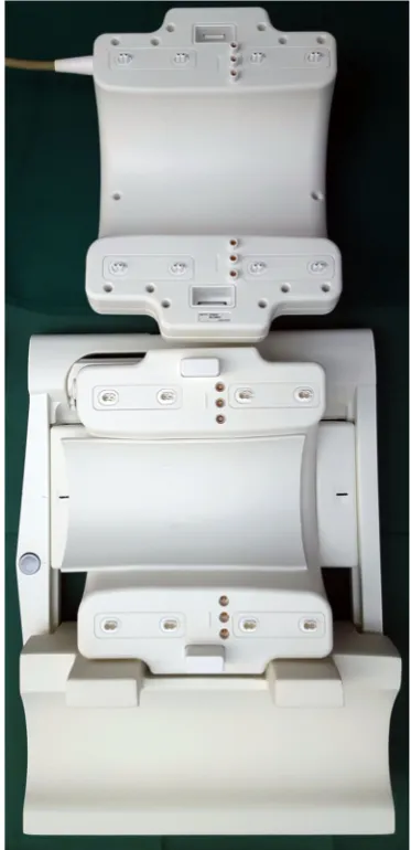
Fig. 2 Photograph of an opened, 28-channel transmit / receive knee coil
(Quality Electrodynamics, Mayfield Village, OH) for a 7.0 T MR system (Philips, Best, the Netherlands) that includes the coil as well as a special adapter box (left) that connects the coil to the MR system
Fig. 1 Photograph of an opened, commercially available, dedicated
images (Fig.1). As higher magnetic field systems (3.0 T, 4.0 T and 7.0 T) are used more and more often in clinical settings and research areas, the limits of performance in pulse se-quence acquisition efficiency is approaching the limits [11]. Optimization of RF coils is seen as one of the solutions for further improvement [11]. Recently, dedicated 28-element RF coils with high acceleration factors have been developed for imaging at 7.0 T with very high-resolution (Fig.2) [12]. However, all these developments imply significant costs and the decision makers must consider the benefits of the invest-ment based on an analysis of effectiveness in relation to cost. The authors, however, strongly recommend the use of dedi-cated knee coils.
Protocol considerations
The clinical imaging protocol of the knee includes different MRI sequences with high-spatial resolution in all orientations: sagittal, coronal, and axial (Table1). The spatial resolution should be maximized by using small field-of-view, thin slices, and high matrix size. The recommended field-of-view is 16 cm, but it also depends on the joint size and on the type of the radiofrequency coil used. Usually, the slice thickness is
3 mm or less, even with standard two-dimensional fast spin echo sequences. For axial images, the thinner the slice thick-ness, the better possible evaluation of the meniscal roots (Fig. 3). However, the increase in resolution decreases the signal-to-noise ratio. Although this is a limiting factor, it usu-ally may not be a problem when dedicated knee coils are used at high magnetic field strengths (3.0 T and 7.0 T). Most clin-ical MR scanners on the market (1.5–3.0 T) provide excellent image quality even when high resolution images (in-plane and through-plane) are the desired goal.
Although MRI examination of the knee is relatively fast, it is not uncommon for the protocols to beBoptimized^in clin-ical practice to shorten the acquisition time even more. However, technical improvements should be used to increase image quality and diagnosis accuracy, rather than to shorten the protocols.
Examination planes
Several meniscal lesions are best evaluated on sagittal images, including meniscal avulsion, radial tears (Bghost^ meniscus s i g n ) , t e a r s o f t h e a n t e r i o r h o r n s , a n d p o s t e r i o r meniscocapsular separation (Figs. 4 and 5). Moreover, as
Fig. 3 Set of two axial
proton-density–weighted fat-suppressed fast spin echo images in a 42-year-old female patient, acquired at 2.5 mm slice thickness (a) and 5 mm slice thickness (b). With thinner slices, the meniscal root ligaments of the anterior horn of the medial meniscus (arrows) are much better appreciated. With thicker slices, these ligaments are barely visible, mainly due to partial volume effects
Table 1 Example for an MR imaging protocol of the knee
Orientation Sequence type Repetition time / echo time [ms]
Fat suppressed
Resolution (mm)
Acquisition time [ms]
sagittal proton-densitiy turbo spin echo 3000 / 29 No 0.2. × 0.2 × 2.8 3:35 sagittal T2-weighted turbo spin echo 4600 / 83 Yes 0.2. × 0.2 × 2.8 7:42 coronal proton-densitiy turbo spin echo 2770 / 25 No 0.2. × 0.2 × 3.0 5:26 transverse proton-densitiy turbo spin echo 6230 / 41 Yes 0.2. × 0.2 × 2.5 4:29
many as 82 % of the meniscal tears are identified on sagittal images only [13]. The diagnosis mainly relies on the identifi-cation of an intrameniscal linear signal change and its contact with the meniscal surfaces. This includes that acquisition pa-rameters are tailored such that potential meniscus tear can be detected, e.g. by having long echo time (TE) acquisitions for better fluid sensitivity. The number of the sagittal images in which the linear signal change contacts the meniscal surface may be an important factor in diagnostic accuracy and diag-nostic confidence. The positive predictive value for diagnos-ing meniscal tears increases from 53 %, when the diagnosis is based on only one sagittal image in which the linear change extends to one of the meniscal surfaces, to 90 %, when the longitudinal linear signal contacts the meniscal surface in two consecutive sagittal images [5]. Therefore, in order to avoid false-positive reports, it is recommended that linear signal changes that contact the meniscal surface solely on one image are reported as possible tears [5, 10]. The false-positive
diagnosis is even more likely in cases in which the intrameniscal signal contacts only the superior meniscal sur-face on sagittal images [5]. A correct evaluation of some par-ticular types of tears (bucket-handle tears and radial tears) is difficult when it is based solely on sagittal images [13,14]. In these cases, the images obtained in coronal and axial orienta-tions play an important role.
Coronal imagesprovide valuable information regarding meniscal shape and its attachments. Some types of meniscal tears are better characterized on coronal images combined with sagittal images when compared to sagittal images alone [13]. Other types of meniscal tears (e.g. small radial tears) may be seen only in the coronal plane [13]. The horizontal tears that are seen on sagittal images may not always be accurately described with regard to the relation with the meniscal surface. In those cases, the evaluation of the coronal images allows a better evaluation of the lesion, especially when located in the body of the meniscus [13]. The coronal plane is particularly useful in diagnosing bucket-handle tears, detached meniscal fragments, and meniscal extrusions beyond the tibial plateau (Fig.6). Meniscal root tears are also highly accurately diag-nosed on coronal images [15].
Axial imagesare always part of clinical knee protocols and are routinely used for evaluation of the patellofemoral joint and ligaments. In the evaluation of menisci, it has been shown that diagnostic accuracy and diagnostic confidence of axial images are lower only when compared to sagittal and coronal images [16]. However, axial images are complementary to
Fig. 6 Coronal proton-density–weighted fast spin echo image of the
right knee in a 25-year-old male patient with a traumatic osteochondral defect at the medial femoral condyle shows displacement of the medial meniscus and complete rupture of the meniscofemoral ligament (arrow). The more superficial medical collateral ligament (arrowhead) shows only mild abnormalities with thickening at its femoral insertion. Note the normal meniscotibial ligament (small arrow)
Fig. 5 Sagittal T2-weighted, fat-suppressed fast spin echo image of the
right knee in a 25-year-old male patient shows a complex tear (two parallel vertical longitudinal tears) of the posterior horn of the medial meniscus with three fragments (arrow), as well as a traumatic articular cartilage defect (arrowhead) with complete loss of an osteochondral fragment
Fig. 4 Sagittal T2-weighted, fat-suppressed fast spin echo image of the
sagittal and coronal planes and may better show the whole extent of a meniscal tear (Fig.7) [16]. It was shown that radial tears, complex tears (i.e. flap tears), and displaced fragments may be better visualized and localized in axial planes when high-resolution images are obtained (Fig.8) [16–18].
Pulse sequences
The routinely used MRI sequences are two-dimensional (2D), fast spin-echo (FSE) sequences (proton-density (PD)-weighted, T1—weighted sequences, and T2- and T1—weighted se-quences with and without fat suppression). When comparing with spin-echo (SE) sequences, FSE sequences facilitate the examination in a shorter overall time without statistically sig-nificant differences in meniscal tear detection rate [19]. By using high-magnetic field strength with dedicated coils, and parallel imaging techniques, the scan time may be decreased even more. Some particular types of meniscal tears have been proven to be better evaluated on specific sequences (e.g. coro-nal T2-weighted images showed a 96 % diagnostic accuracy compared with 85 % accuracy of PD-weighted coronal images for diagnosis of medial meniscal roots tears) [15].
Most authors still prefer standard two-dimensional over three-dimensional fast spin echo sequences and over gradient echo sequences, because the former provide classic, well-known T1-, T2-, and intermediate-weighted contrast informa-tion and enable detecinforma-tion of subtle abnormalities of the me-niscus and ligaments. This is in contradiction to the fact that with three-dimensional (3D) gradient-echo (GRE) and 3D fast spin-echo FSE sequences, thinner sections with decreased par-tial volume averaging and isotropic voxel imaging with multiplanar reformations (that potentially reduce the examina-tion time) are possible. Indeed, several studies have shown that 3D isotropic FSE sequences can provide rapid knee joint eval-uation. By using 3D fat-saturated PD FSE sequences at 3.0 T with isotropic resolution between 0.4 mm to 0.7 mm with ac-quisition times between 5 and 10 minutes, the authors found similar sensitivities and specificities as the routine MR protocol for detecting knee joint lesions [20–22]. However, the diagnos-tic performance of 3D sequences is not significantly increased in the overall evaluation of the meniscal tears [20,23–25]. The exception might be the diagnosis of meniscal roots tears that can benefit from the better visualization of small structures by using 3D FSE images [24,26]. Other authors considered that the image quality of the 3D sequences is lower compared with
Fig. 8 Axial proton-density–
weighted fat-suppressed fast spin echo image (a) of the left knee in a 56 years old male patient shows an extra-articularly displaced fragment (arrow) of the medial meniscus. Coronal proton-density–weighted fast spin echo image (b) confirms the diagnosis and shows that the flapped por-tion (arrow) is still in continuity with the meniscus remnant (arrow)
Fig. 7 Sagittal proton-density–weighted fast spin echo image (a) of the
right knee in a 25-year-old male patient with a severe knee trauma shows a fracture line (arrow) within the tibia and intrameniscal signal changes at the level of the anterior root (small arrow). Axial proton-density–
2D FSE sequences, and the diagnostic confidence of the radi-ologists is still higher with the 2D sequences regarding the meniscal evaluation [24]. This difference might be the result of the decreased visualization of low contrast structures, such as meniscus, with the 3D sequences [24].
Recently, synthetic-echo time post-processing techniques for generating images with variable T2-weighted contrast demonstrated high sensitivity and specificity in evaluation of abnormalities of menisci [27]. Commercially available
synthetic imaging techniques are currently being developed by some vendors, i.e. for brain imaging, and it is only a matter of time before we will see further clinical trials in the muscu-loskeletal system as well [27]. MR fingerprinting may also be a future development that could dramatically change the way we assess meniscus. Both quantitative and qualitative evalua-tion could be possible from only one acquisievalua-tion, as well as reconstruction of images with different contrast information [28]. However, MR fingerprinting and synthetic imaging has yet to be given research status, although they will be available soon by at least one vendor. Currently, synthetic techniques for meniscal imaging should not yet be used routinely as there is only very little evidence.
Another important development that will soon likely find its way into clinical routine (3–5 years) is the acceleration of 2D sequences by multi-slice acquisition techniques. The po-tential reduction of acquisition time is in the range of twofold to threefold [29,30]. Since the original sequences and their contrast remain unchanged, the acceptance of these new se-quences and their adoption to clinical imaging protocols will likely be very high amongst musculoskeletal radiologists.
Magnetic field strength
Over the last decade, the expectations in terms of diagnosis accuracy has increased with the deployment of higher mag-netic field strength. In many places, 3.0 T systems have re-p l a c ed t h e 1 . 5 T e q u i re-p m e n t a s s t a n d a r d o f c a r e . Musculoskeletal imaging is one of the fields that gains signif-icantly from higher magnetic field strength when appropriate adaptation of pulse sequence parameters and high perfor-mance dedicated coils are used. The 3.0 T scanners have shown a significant improvement in visualization and evalua-tion of small structures such as ligaments, nerves, and articular cartilage compared to 1.5 T systems [31–33]. In addition, 4.0 T and 7.0 T MR units are increasingly available. Until
Fig. 10 Axial proton-density–weighted fat-suppressed fast spin echo
image in a 51-year-old female patient shows a (relatively thick) normal intermeniscal ligament (arrow) and normal anterior root of the medial meniscus (small arrow) and of the lateral meniscus (arrowhead)
Table 2 Tibial insertions of the meniscal roots and meniscal roots tear
MRI findings [41,50–54]
Meniscal root ligament
Tibial insertion relative to cruciate ligaments
Meniscal root tear–MRI findings
Direct findings Associated findings Anterior
medial root
7 mm anterior to the anterior cruciate ligament (ACL)
Ghost meniscal sign on sagittal images
Cartilage defect
Posterior medial root
8 mm anterior to the most superior insertion of the posterior cruciate ligament (PCL)
Linear defect on coronal images (truncation sign)
Medial or lateral meniscal extrusion1
Anterior lateral root
4.1 mm lateral to the posterolateral bundle of ACL
Radial linear defect on axial images
Tear of ACL
Posterior lateral root
10.8 mm posterior to ACL and 12.7 mm anterior to PCL
1
Meniscus is displaced beyond the tibial margin—on coronal images, a distance more than 3 mm for the medial meniscus and more than 1 mm for the lateral meniscus is considered abnormal [47]
Fig. 9 Axial proton-density–weighted fat-suppressed fast spin echo
now, more than 65 installed MR systems worldwide operating at 7.0 T have been established as platforms for clinically ori-ented research. The introduction of the 7.0 T scanner has pushed the possibilities of morphological, functional, meta-bolic and diffusion-weighted imaging of the tendons, carti-lage, and trabecular bone significantly forward (Fig. 9) [34–37].
Although, there are data that show that higher mag-netic field strength improves the diagnostic performance for anterior cruciate ligament (ACL) tears, cartilage and subchondral bone, the evidence regarding the added clini-cal value of higher fields MRI for menisclini-cal tear evaluation is limited and is still a subject of debate [6]. Some authors consider that there is no significant difference for meniscal tear accuracy between magnetic field strengths ranging from 1.5 T to 7.0 T [6, 38–40]. However, as a result of an increased spatial resolution and increased signal-to-noise ratio, the detection and characterization of small tears (e.g. of the free margin of the meniscus), small radial tears, or tears of the meniscal roots are better assessed when higher magnetic fields are used. Therefore, we consider that higher magnetic field strengths may improve the diag-nosis accuracy and diagdiag-nosis confidence, and we recom-mend that knee examinations at 3.0 T scanners should be used, at this moment, as the new standard in clinical practice.
Typical pitfalls
Whereas most radiologists and clinicians are well aware of classic signs for meniscal tears (in either the anterior horn, body or posterior horn), typical pitfalls in the diagnosis in-volve the meniscal roots and inter-meniscal connections, as well as the ligamentous attachment of the medial and lateral meniscus. Knowledge of the normal anatomy is key for diag-nosis. The subsequent paragraphs provide a comprehensive overview of typical pitfalls; classic signs are briefly reviewed.
Meniscal roots and inter-meniscal connections
The anterior and posterior horns of the menisci are firmly attached to the tibial plateau through the insertional ligaments known as the meniscal root ligaments. They have an important role in knee biomechanics and kinematics by securing the meniscus in place and acting as anchors to the bone for both menisci [41]. Although meniscal root tears are less common than other types of meniscal tears, they can have a significant clinical impact. Cartilage defects and extrusion of the menis-cus with respect to the tibial margin have been linked with tears of the meniscal roots [41–46]. There are three types of meniscal root lesions: avulsion injuries of the attachments, radial tears, and degenerative changes. Usually, they are locat-ed within few millimetres from the bony insertion [47]. An
Fig. 12 Standard radiograph (a) of the right knee in a 42-year-old male
patient with a mild knee trauma shows typical signs of chondrocalcinosis with calcification (small arrows) within the articular space. Sagittal T2 weighted fat-suppressed fast spin echo image (b) shows traumatic bone marrow abnormalities (arrowhead) within the lateral femoral condyle and
an oblique tear of the root of the anterior horn of the lateral meniscus (arrow). The tear should not be misinterpreted as the anterior transverse ligament or the geniculate ligament (small arrow), which is relatively thin, but intact in this patient
Fig. 11 Coronal proton-density–weighted fast spin echo image (a) of the
right knee in a 36-year-old male patient with a severe knee trauma shows a complex meniscocapsular injury, affecting both the posterior root of the medial meniscus and the posterior horn (arrow). Sagittal proton-density–
accurate diagnosis of such lesions as well as of associated injuries are mandatory for the treatment decision, i.e. nonop-erative versus opnonop-erative, in order to avoid a poor clinical out-come and long-term prognosis. Meniscal root tears are, in many cases, unrecognized and neglected in the MRI reports. In the literature, it is reported that, e.g. one-third of the tears of the posterior medial root are missed [48,49]. Visualization of the meniscal roots on MRI is challenging, but increased awareness of the normal anatomy and the imaging signs of meniscal roots tears may improve the diagnosis accuracy (Table2). It is important to keep in mind that the anatomy of the meniscal roots is not uniform and that there are slight differences in terms of the exact attachment site as well as MR appearance.
Medial meniscal roots
The tibial attachment of the anterior horn of the medial me-niscus or the anterior medial root ligament is situated at the intercondylar fossa, anteriorly to the anterior cruciate ligament (ACL) attachment (Fig.10) (Table2) [50]. In 59 % of the cases, the anterior horn of the medial meniscus is attached to the anterior cruciate ligament (ACL) [51]. The insertion area of the anterior medial root is the largest of any of the meniscus attachments [50–55]. Anatomically, four types of insertions have been described, but an accurate classification of these variants based on MR images is hardly possible and of no clinical relevance [56].
The posterior medial root ligament attaches the posterior horn of the medial meniscus with the posterior intercondylar tibial fossa. The attachment site is situated between the inser-tion of the posterior lateral root ligament and the inserinser-tion of the posterior cruciate ligament (PCL) (Table2) [57]. The pos-terior medial root ligament has the least mobility of all menis-cus roots ligaments, and this may be the cause of the highest incidence of injuries compared with the other roots (Fig.11) [58,59]. Thus, after knee trauma, the posterior medial root ligament should be evaluated with extra care. Tears of medial meniscal roots are often associated with degenerative meniscal disease [60].
Lateral meniscal roots
The anterior lateral meniscal root ligament attaches the ante-rior horn of the lateral meniscus to the lateral intercondylar tibial eminence just behind the anterior cruciate ligament (ACL) insertion (Figs.10and12) (Table2) [57]. It has been demonstrated that the anterior horn of the lateral meniscus is also attached to the anterior cruciate ligament (ACL) [51]. The posterior root ligament of the lateral meniscus attaches poste-rior to the lateral intercondylar tibial eminence and anteposte-rior to the medial posterior root ligament (Table 2) [57]. Posterior
lateral root tear is highly associated with tear of the anterior cruciate ligament (ACL) [60].
Inter-meniscal ligaments
The anterior transverse ligament, or the geniculate ligament, connects the anterior horns of the medial and lateral meniscus (Fig.10). Medially, the transverse ligament blends with the posterior attachment of the anterior medial root ligament [56].
Fig. 14 Coronal proton-density–weighted fast spin echo image in a
20-year-old female patient shows normal meniscotibial (small arrow), meniscofemoral (arrowhead) and medial collateral ligaments (large arrow)
Fig. 13 Sagittal proton-density–weighted fast spin echo image of the
The ligament is inconsistently present, but, when present, there is an association between the transverse ligament attach-ment and the presence of tears in the medial meniscus as a result of restricting effect on anterior-posterior excursion of the anterior horn of the medial meniscus at lower degrees of knee flexion [61,62]. The best planes for visualization of the ligament are sagittal and coronal [63]. On sagittal images, the presence of the geniculate ligament may lead to false-positive diagnosis of vertical longitudinal tear of the anterior horn or of displaced meniscal fragments (Fig.13). The posterior trans-verse ligament is present much more rarely than the anterior transverse ligament [64]. It connects the posterior horns of the medial and lateral meniscus. It is seen on MR images, when present, on the coronal plane in front of the posterior cruciate ligament. Inconsistently, two oblique meniscomeniscal liga-ments may be recognized on MR images [65]. The oblique ligaments extend from the anterior horn of the medial menis-cus to the posterior horn of the lateral menismenis-cus (medial oblique ligament) and from the anterior horn of the lateral
meniscus to the posterior horn of the medial meniscus (lateral oblique ligament) [65].
Capsular attachments
Medial meniscus
The attachment of the medial meniscus to the capsule is com-plex, and tears at this level are not always recognized and/or correctly described. The medial meniscus is closely attached to the knee capsule along its entire circumference [64]. The meniscofemoral, the meniscotibial, and the meniscopatellar ligaments are the structures that define the deep layer (layer 3) of the medial collateral ligament (Fig. 14) [64]. The meniscofemoral ligament is seen on MR images as a thin band that originates from the superior margin of the body of the medial meniscus and inserts on the femoral condyle 1–2 cm
Fig. 18 Coronal proton-density–weighted fast spin echo image in a
19-year-old male patient shows the normal anterior meniscofemoral ligament (Humphrey ligament) (large arrow) inferior to the posterior cruciate ligament (small arrow)
Fig. 17 Coronal proton-density–weighted fast spin echo image in a
47-year-old female patient shows the normal posterior meniscofemoral ligament (also referred to as Wrisberg ligament) extending from the posterior horn of the lateral meniscus to the medial femoral condyle (large arrow). Note a radial tear of the posterior horn of the medial meniscus (small arrow)
Fig. 16 Sagittal proton-density–weighted fast spin echo image in a
40-year-old female patient shows the normal popliteomeniscal fascicles (PMF), which include the posterosuperior (arrow) and the anteroinferior fascicles (small arrow)
Fig. 15 Coronal T2-weighted fat-suppressed fast spin echo image in a
above the joint line [66]. The meniscotibial ligament is shorter and connects the inferior margin of the medial meniscus to the tibial cortex inferior to the joint line [66]. The meniscotibial ligament extends along the entire circumference of the posteromedial edge of the meniscus and further forms the deepest layer of the capsule. It is also called the coronary ligament or the meniscocapsular ligament [64]. The patellomeniscal ligament is seen on MR images anteriorly
from the medial meniscus to the patellar margin [67]. A small bursa, known as medial posterior femoral recess or medial gastrocnemius bursa, separates the posterior horn of the me-dial meniscus from the joint capsule [68]. The presence of a small amount of fluid should not be misinterpreted as a meniscocapsular separation (Fig.15).
Coronal MR images are particularly useful in demon-strating tears of the meniscofemoral and meniscotibial
Table 3 Meniscal tear classification [1,64,75–78]
Meniscal tear
Vertical Longitudinal Incomplete (linear signal changes only involving one meniscal surface)
Stable Low clinical relevance, not always correlated with symptoms =Bleave alone^ lesion
Complete (linear signal changes involve both meniscal surface)
Unstable when meniscocapsular separation is present or in extensive lesion
High clinical relevance
Radial Without meniscal
root involvement
Usually unstable High clinical relevance
Radial meniscal root tear Horizontal or
oblique-horizontal
Incomplete (linear signal changes not involving a meniscal surface)
Stable Low clinical relevance, not always correlated with symptoms =Bleave alone^lesion Complete (linear signal changes involving one
or more meniscal surfaces)
Unstable/stable Different clinical relevance depending on associated lesions, e.g. anterior cruciate ligament (ACL) tear, medial collateral
ligament (MCL) tear Complex Horizontal and vertical tear,
complex linear pattern
Unstable High clinical relevance
Bucket-handle Flap tears (including
parrot beak tears) Free meniscal
fragment
Fig. 19 Sagittal proton-density–weighted fast spin echo images in a
43-year-old female patient through the lateral meniscus. At the insertion of the posterior meniscofemoral ligament (a), the ligament (large arrow) closely parallels the outer posterior margin of the posterior horn of the lateral meniscus (small arrow). The linear signal between the
ligaments (Fig.14) [64]. It should be noted, that tears of these ligaments can occur in isolation, with the more superficial layer of the medial collateral ligament appearing normal or slightly abnormal at the same time (Fig.6). Nevertheless, it is important to recognize lesions of these attachments, as they stabilize the medial meniscus.
The presence of fluid with an increased distance between the medial collateral ligament and the medial meniscus, the displacement of meniscus from the tibia, a tear within the peripheral zone of the medial meniscus, and irregular meniscal margins are the best predictors of medial meniscocapsular separation (Fig.11) [69]. The key sign for meniscocapsular separation is the presence of an abnormal signal intensity be-tween the meniscus and the capsule or within the peripheral zone of the meniscus [64].
Lateral meniscus
Unlike the medial meniscus, there is no attachment of the lateral meniscus to the lateral collateral ligament [64]. The lateral meniscus is attached to the tibia along its entire circum-ference through the lateral meniscotibial ligament, also known as the coronary ligament or the meniscocapsular ligament. The lateral meniscus is also strongly attached to the popliteus tendon and to the medial femoral condyle. Knowledge of the anatomy of these attachments is important in order to avoid reporting false positive diagnoses of posterior horn meniscal tears or free meniscal fragments. The popliteomeniscal fasci-cles (PMF) are part of the posterolateral corner of the knee and connect the posterior horn of the lateral meniscus with the p o p l i t e a l t e n d o n ( F i g . 1 6) . T h e p o s t e r o s u p e r i o r popliteomeniscal fascicles extend from the posterolateral as-pect of the lateral meniscus to the popliteus tendon, and the anteroinferior popliteomeniscal fascicles extend from the mid-dle third of the lateral meniscus to the popliteus tendon [70]. The anteroinferior popliteomeniscal fascicles are stronger and shorter than the posterosuperior popliteomeniscal fascicles [71,72]. On MR images, they are inconsistently seen as hypointense structures on sagittal planes (Fig.16) [70]. A displaced lateral meniscus and the disruption of the popliteomeniscal fascicles with high-signal intensity soft tis-sue oedema with or without perimeniscal fluid are suggestive of a possible lateral meniscocapsular separation [73].
The posterior horn of the lateral meniscus attaches to the medial femoral condyle through the commonly well-known meniscofemoral ligaments. The posterior meniscofemoral lig-ament (also referred to as Wrisberg liglig-ament) extends from the posterior horn of the meniscus to the medial femoral condyle proximal to the posterior cruciate ligament (PCL) insertion (Fig.17). The anterior meniscofemoral ligament (also referred to as Humphrey ligament) attaches on the medial femoral condyle, inferior to the posterior cruciate ligament insertion (Fig. 18). Many variations of these ligaments have been
reported, and the incidence of the presence of one or the other ligament is 70–100 % [74]. At their meniscal origin, the liga-ments closely parallel the outer posterior margin of the menis-cus, and, on sagittal images, the linear signal between the low-intensity meniscus and the low-low-intensity ligaments may lead to pitfalls and could be confused with a tear (Fig.19).
Isolated lesions of the ligament of Humphrey or Wrisberg are rare. Most often, the ligaments are affected by tears of the posterior horn when both ligaments may show a wavy course. On the other hand, isolated distortions of the ligaments are an indirect sign for lateral meniscal root tears.
Patterns and classification of meniscal tears
An accurate description of meniscal tears is of utmost impor-tance. A comprehensive report includes the exact localization, orientation, and extension of the meniscal tear. For the latter, it should always be noted to which surface the tear extends to (femoral surface or tibial surface). A clear description may obviate unnecessary surgery or may enable a better surgical planning.
The traditional description of a meniscal tear is that of a linear increased signal intensity within the meniscus.
Fig. 21 Sagittal proton-density–weighted fast spin echo image of the left
knee in a 22-year-old male patient with a bucket handle tear of the medial meniscus shows the displaced anterior horn (arrow) which lies posterior to its root insertion (arrowhead). Note the relatively thick intermeniscal ligament (small arrow) that normally connects both anterior horns of the menisci as well as the small non-displaced remnant of the posterior horn
Fig. 20 Coronal proton-density–weighted fast spin echo image of the
According to the orientation, a meniscal tear can be vertical, horizontal, or complex (Table3). An horizontal tear is defined as a linear signal abnormality involving the surface of the meniscus in a horizontal orientation of less than 30° relative to the adjacent tibial plateau (Fig.20) [5]. Vertical tears are subdivided into radial and longitudinal tears. Radial tears are perpendicular to the long axis of the meniscus and begin in the free edge of the meniscus (Fig.4) [5,75]. Vertical longitudinal tears are parallel to the long axis of the meniscus, away from the free edge (Fig.5) [5,75]. A complex tear refers to a com-bination of more orientations (e.g. parrot beak tear). Tears with displaced fragments such as bucket-handle tear, flap meniscus tear, or free meniscus fragment are also classified as complex tears (Figs.21and22).
Meniscal grading, e.g. grade I, II, or III, which has been widely used in the past, is now considered obso-lete in clinical routine imaging [79]. As with many clas-sifications in musculoskeletal imaging, multiple versions of the same classification system were used, mixed up, or inconsistently used. This often caused misunderstand-ing, i.e. the referring physician could not distinguish between important and non-important lesions. Thus, a standard knee report may better distinguish between sta-ble and unstasta-ble tears (Tasta-ble 3), if there is a need for a classification system at all. Therefore, the orientation, the extension and involvement of meniscal surfaces (none, one, or both) are important features that should be recognized and described in the report. Stable tears (Fig. 20) have a potential for healing conservatively, whereas unstable tears often require surgery [1, 76]. It should be noted that the natural healing of meniscal tears might cause problems in the evaluation of follow-up MR images. Spontaneous healing is often as-sociated with the presence of haemorrhage around the meniscal lesion [80]. Meniscal healing should not be misinterpreted as early re-tear.
The evaluation of post-operative meniscus can be challenging, e.g. when information about the type of prior surgery is not provided. The type of surgery
defines the post-operative meniscus appearance. The two typical surgical approaches are meniscus preserving versus non-preserving therapies. The former includes meniscal suture, glueing, needle trephination or synovial abrasion. Non-preserving therapies include partial or to-tal meniscectomy. Accordingly, normal intrasubstance changes in the operated meniscus after preservation sur-gery must be differentiated from a re-tear, which is usu-ally characterized by a linear abnormal signal intensity that is more hyperintense than seen in healing meniscus. Intra-articular contrast application may help to differen-tiate re-tears (where the contrast is leaking into the cleft) from healing (where granulation and scar tissue fills up the cleft and where the contrast has no space to leak in). Missing parts of the meniscus may disclose non-preserving therapy. Sharp or truncated meniscal edges and loss of substance indicate meniscectomy.
A special category is the surgical repair of root tears. Usually, they challenge the surgeon in that the meniscus must be re-attached to bone. Surgeons may use arthroscopically assisted bone suture anchors (all-inside technique) or an intraosseous suture technique (Bpullout technique^) [81]. To avoid misinterpretation of post-operative MR images, details about the type of surgery and the procedure are mandatory.
Conclusion
Magnetic resonance imaging represents a standard tool in knee evaluation with a high specificity and sensitivity in diagnosing meniscal tears. However, in order to avoid errors of interpretations and pitfalls, there are sev-eral factors that should be taken into consideration. The technical platform and the sequence parameters, the awareness of the normal meniscal anatomy, and the knowledge of the patterns of the tears may influence the accuracy of diagnosis. An accurate and a complete
Fig. 22 Sagittal T2 weighted fat-suppressed (a) and corresponding
proton-density (PD) weighted fast spin echo image (b) of the right knee in a 73-year-old female patient with a bucket handle tear show the classic
description of meniscal tears is important and influences treatment planning.
Acknowledgments We thank Mrs. Suzanne Potter for her help with
acquiring some images and Table1.
References
1. Zanetti M et al (2003) Patients with suspected meniscal tears: prev-alence of abnormalities seen on MRI of 100 symptomatic and 100 contralateral asymptomatic knees. AJR Am J Roentgenol 181(3): 635–641
2. De Smet AA (2012) How I diagnose meniscal tears on knee MRI. AJR Am J Roentgenol 199(3):481–499
3. Metcalf MH, Barrett GR (2004) Prospective evaluation of 1485 meniscal tear patterns in patients with stable knees. Am J Sports Med 32(3):675–680
4. Robinson S et al (2011) Meniscal tears: epidemiology and correla-tion between clinical and arthroscopic findings. J Bone Joint Surg Br 93-B(SUPP II)
5. De Smet AA et al (2008) Clinical and MRI findings associated with false-positive knee MR diagnoses of medial meniscal tears. AJR Am J Roentgenol 191(1):93–99
6. Oei EH et al (2003) MR imaging of the menisci and cruciate liga-ments: a systematic review. Radiology 226(3):837–848
7. Rosas HG (2014) Magnetic resonance imaging of the meniscus. Magn Reson Imaging Clin N Am 22(4):493–516
8. Crues JV 3rd et al (1987) Meniscal tears of the knee: accuracy of MR imaging. Radiology 164(2):445–448
9. Rubin DA, Paletta GA Jr (2000) Current concepts and controver-sies in meniscal imaging. Magn Reson Imaging Clin N Am 8(2): 243–270
10. Kaplan PA et al (1991) MR of the knee: the significance of high signal in the meniscus that does not clearly extend to the surface. AJR Am J Roentgenol 156(2):333–336
11. Asher KA et al (2010) Radiofrequency coils for musculoskeletal magnetic resonance imaging. Top Magn Reson Imaging 21(5):315– 323
12. Chang G et al (2015) 7 Tesla MRI of bone microarchitecture dis-criminates between women without and with fragility fractures who do not differ by bone mineral density. J Bone Miner Metab 33(3): 285–293
13. Magee T, Williams D (2004) Detection of meniscal tears and mar-row lesions using coronal MRI. AJR Am J Roentgenol 183(5): 1469–1473
14. De Smet AA et al (1993) MR diagnosis of meniscal tears of the knee: importance of high signal in the meniscus that extends to the surface. AJR Am J Roentgenol 161(1):101–107
15. Lee SY, Jee WH, Kim JM (2008) Radial tear of the medial meniscal root: reliability and accuracy of MRI for diagnosis. AJR Am J Roentgenol 191(1):81–85
16. Tarhan NC et al (2004) Meniscal tears: role of axial MRI alone and in combination with other imaging planes. AJR Am J Roentgenol 183(1):9–15
17. Araki Y et al (1992) MR diagnosis of meniscal tears of the knee: value of axial three-dimensional Fourier transformation GRASS images. AJR Am J Roentgenol 158(3):587–590
18. Aubel S et al (1992) MR knee imaging: axial 3DFT GRASS pulse sequence versus spin-echo imaging for detecting meniscal tears. Magn Reson Imaging 10(4):531–539
19. Hopper MA, Robinson P, Grainger AJ (2011) Meniscal tear evalu-ation. Comparison of a conventional spin-echo proton density se-quence with a fast spin-echo sese-quence utilizing a 512 × 358 matrix size. Clin Radiol 66(4):329–333
20. Jung JY et al (2009) Diagnosis of internal derangement of the knee at 3.0-T MR imaging: 3D isotropic intermediate-weighted versus 2D sequences. Radiology 253(3):780–787
21. Kijowski R et al (2009) Knee joint: comprehensive assessment with 3D isotropic resolution fast spin-echo MR imaging–diagnostic per-formance compared with that of conventional MR imaging at 3.0 T. Radiology 252(2):486–495
22. Notohamiprodjo M et al (2009) MRI of the knee at 3T: first clinical results with an isotropic PDfs-weighted 3D-TSE-sequence. Invest Radiol 44(9):585–597
23. Duc SR et al (2008) Internal knee derangement assessed with 3-minute three-dimensional isovoxel true FISP MR sequence: prelim-inary study. Radiology 246(2):526–535
24. Ristow O et al (2009) Isotropic 3D fast spin-echo imaging versus standard 2D imaging at 3.0 T of the knee–image quality and diag-nostic performance. Eur Radiol 19(5):1263–1272
25. Jung JY et al (2012) Meniscal tear configurations: categorization with 3D isotropic turbo spin-echo MRI compared with convention-al MRI at 3 T. AJR Am J Roentgenol 198(2):W173–W180 26. Kijowski R et al (2012) Evaluation of the menisci of the knee joint
using three-dimensional isotropic resolution fast spin-echo imag-ing: diagnostic performance in 250 patients with surgical correla-tion. Skeletal Radiol 41(2):169–178
27. Andreisek G et al (2010) Synthetic-echo time postprocessing tech-nique for generating images with variable T2-weighted contrast: diagnosis of meniscal and cartilage abnormalities of the knee. Radiology 254(1):188–199
28. European Society of, R (2015) Magnetic Resonance Fingerprinting - a promising new approach to obtain standardized imaging bio-markers from MRI. Insights Imaging 6(2):163–165
29. Setsompop K et al (2012) Blipped-controlled aliasing in parallel imaging for simultaneous multislice echo planar imaging with re-duced g-factor penalty. Magn Reson Med 67(5):1210–1224 30. Filli L et al (2015) Simultaneous multislice echo planar imaging
with blipped controlled aliasing in parallel imaging results in higher acceleration: a promising technique for accelerated diffusion tensor imaging of skeletal muscle. Invest Radiol 50(7):456–463 31. Saupe N et al (2005) MR imaging of the wrist: comparison between
1.5- and 3-T MR imaging–preliminary experience. Radiology 234(1):256–264
32. Thakkar RS et al (2012) Spectrum of high-resolution MRI findings in diabetic neuropathy. AJR Am J Roentgenol 199(2):407–412 33. Chhabra A et al (2013) Anatomic MR imaging and functional
dif-fusion tensor imaging of peripheral nerve tumors and tumorlike conditions. AJNR Am J Neuroradiol 34(4):802–807
34. Juras V et al (2012) Sodium MR imaging of Achilles tendinopathy at 7 T: preliminary results. Radiology 262(1):199–205
35. Zbyn S et al (2012) Evaluation of native hyaline cartilage and repair tissue after two cartilage repair surgery techniques with 23Na MR imaging at 7 T: initial experience. Osteoarthritis Cartilage 20(8): 837–845
36. Wurnig MC et al (2014) Characterization of trabecular bone density with ultra-short echo-time MRI at 1.5, 3.0 and 7.0 T–comparison with micro-computed tomography. NMR Biomed 27(10):1159– 1166
37. Trattnig S et al (2015) Clinical applications at ultrahigh field (7 T). Where does it make the difference? NMR Biomed
38. Magee T, Williams D (2006) 3.0-T MRI of meniscal tears. AJR Am J Roentgenol 187(2):371–375
39. Nguyen JC et al (2014) MR imaging-based diagnosis and classifi-cation of meniscal tears. Radiographics 34(4):981–999
40. Van Dyck P et al (2014) Comparison of 1.5- and 3-T MR imaging for evaluating the articular cartilage of the knee. Knee Surg Sports Traumatol Arthrosc 22(6):1376–1384
41. Bhatia S et al (2014) Meniscal root tears: significance, diagnosis, and treatment. Am J Sports Med 42(12):3016–3030
42. Lerer DB et al (2004) The role of meniscal root pathology and radial meniscal tear in medial meniscal extrusion. Skeletal Radiol 33(10): 569–574
43. Koenig JH et al (2009) Meniscal root tears: diagnosis and treatment. Arthroscopy 25(9):1025–1032
44. Hein CN et al (2011) Effects of medial meniscal posterior horn avulsion and repair on meniscal displacement. Knee 18(3):189–192 45. Shelbourne KD, Roberson TA, Gray T (2011) Long-term evalua-tion of posterior lateral meniscus root tears left in situ at the time of anterior cruciate ligament reconstruction. Am J Sports Med 39(7): 1439–1443
46. Papalia R et al (2013) Meniscal root tears: from basic science to ultimate surgery. Br Med Bull 106:91–115
47. Brody JM et al (2006) Lateral meniscus root tear and meniscus extrusion with anterior cruciate ligament tear. Radiology 239(3): 805–810
48. Bin SI, Kim JM, Shin SJ (2004) Radial tears of the posterior horn of the medial meniscus. Arthroscopy 20(4):373–378
49. Ozkoc G et al (2008) Radial tears in the root of the posterior horn of the medial meniscus. Knee Surg Sports Traumatol Arthrosc 16(9): 849–854
50. Johnson DL et al (1995) Insertion-site anatomy of the human me-nisci: gross, arthroscopic, and topographical anatomy as a basis for meniscal transplantation. Arthroscopy 11(4):386–394
51. Ziegler CG et al (2011) Arthroscopically pertinent landmarks for tunnel positioning in single-bundle and double-bundle anterior cru-ciate ligament reconstructions. Am J Sports Med 39(4):743–752 52. Zantop T et al (2008) Tunnel positioning of anteromedial and
pos-terolateral bundles in anatomic anterior cruciate ligament recon-struction: anatomic and radiographic findings. Am J Sports Med 36(1):65–72
53. Johannsen AM et al (2012) Qualitative and quantitative anatomic analysis of the posterior root attachments of the medial and lateral menisci. Am J Sports Med 40(10):2342–2347
54. Petersen W et al (2014) Posterior root tear of the medial and lateral meniscus. Arch Orthop Trauma Surg 134(2):237–255
55. Kohn D, Moreno B (1995) Meniscus insertion anatomy as a basis for meniscus replacement: a morphological cadaveric study. Arthroscopy 11(1):96–103
56. Berlet GC, Fowler PJ (1998) The anterior horn of the medical meniscus. An anatomic study of its insertion. Am J Sports Med 26(4):540–543
57. Messner K, Gao J (1998) The menisci of the knee joint. Anatomical and functional characteristics, and a rationale for clinical treatment. J Anat 193(Pt 2):161–178
58. Thompson WO et al (1991) Tibial meniscal dynamics using three-dimensional reconstruction of magnetic resonance images. Am J Sports Med 19(3):210–215, discussion 215–6
59. Jones AO et al (2006) Medial meniscus posterior root attachment injury and degeneration: MRI findings. Australas Radiol 50(4): 306–313
60. Feucht MJ et al (2015) Risk factors for posterior lateral meniscus root tears in anterior cruciate ligament injuries. Knee Surg Sports Traumatol Arthrosc 23(1):140–145
61. Muhle C et al (1999) Transverse ligament and its effect on meniscal motion. Correlation of kinematic MR imaging and anatomic sec-tions. Invest Radiol 34(9):558–565
62. de Abreu MR et al (2007) Anterior transverse ligament of the knee: MR imaging and anatomic study using clinical and cadaveric ma-terial with emphasis on its contribution to meniscal tears. Clin Imaging 31(3):194–201
63. Sintzoff SA Jr et al (1991) Transverse geniculate ligament of the knee: appearance at plain radiography. Radiology 180(1):259 64. Bolog NV, Andreisek G, Ulbrich E (2015) Meniscus, in MRI of the
knee: a guide to evaluation and reporting, Bolog NV, Andreisek G, Ulbrich E, Ed. Springer Heidelberg, Germany. p. 65–93
65. Sanders TG et al (1999) Oblique meniscomeniscal ligament: anoth-er potential pitfall for a meniscal tear–anatomic description and appearance at MR imaging in three cases. Radiology 213(1):213– 216
66. De Maeseneer M et al (2000) Three layers of the medial capsular and supporting structures of the knee: MR imaging-anatomic cor-relation. Radiographics 20:S83–S89
67. Starok M et al (1997) Normal patellar retinaculum: MR and sono-graphic imaging with cadaveric correlation. AJR Am J Roentgenol 168(6):1493–1499
68. Fenn S, Datir A, Saifuddin A (2009) Synovial recesses of the knee: MR imaging review of anatomical and pathological features. Skeletal Radiol 38(4):317–328
69. De Maeseneer M et al (2002) Medial meniscocapsular separation: MR imaging criteria and diagnostic pitfalls. Eur J Radiol 41(3): 242–252
70. Bolog N, Hodler J (2007) MR imaging of the posterolateral corner of the knee. Skeletal Radiol 36(8):715–728
71. Sussmann PS et al (2001) Development of the popliteomeniscal fasciculi in the fetal human knee joint. Arthroscopy 17(1):14–18 72. Diamantopoulos A et al (2005) The posterolateral corner of the
knee: evaluation under microsurgical dissection. Arthroscopy 21(7):826–833
73. LaPrade RF, Konowalchuk BK (2005) Popliteomeniscal fascicle tears causing symptomatic lateral compartment knee pain: diagno-sis by the figure 4 test and treatment by open repair. Am J Sports Med 33(8):1231–1236
74. Heller L, Langman J (1964) The Menisco-Femoral Ligaments of the Human Knee. J Bone Joint Surg (Br) 46:307–313
75. Anderson MW (2002) MR imaging of the meniscus. Radiol Clin North Am 40(5):1081–1094
76. Weiss CB et al (1989) Non-operative treatment of meniscal tears. J Bone Joint Surg Am 71(6):811–822
77. DeHaven KE (1990) Decision-making factors in the treatment of meniscus lesions. Clin Orthop Relat Res 252:49–54
78. Vande Berg BC et al (2001) Lesions of the menisci of the knee: value of MR imaging criteria for recognition of unstable lesions. AJR Am J Roentgenol 176(3):771–776
79. Barber BR, McNally EG (2013) Meniscal injuries and imaging the postoperative meniscus. Radiol Clin North Am 51(3):371–391 80. Yagishita K et al (2004) Healing potential of meniscal tears without
repair in knees with anterior cruciate ligament reconstruction. Am J Sports Med 32(8):1953–1961