Advanced Ceramics Progress
J o u r n a l H o m e p a g e : w w w . a c e r p . i r
Fabrication, Characterization and Process Parameters Optimization of
Electrospun 58S Bioactive Glass Submicron Fibers
Z. Ghaffariana, A. FaghihImania, A. Doostmohammadia*, M. R. Saeria
a Department of Materials, Faculty of Engineering, Shahrekord University, Shahrekord, Iran
P A P E R I N F O
Paper history:
Received 27 June 2015
Accepted in revised form 14 February 2016
Keywords:
Submicron fibers Bioactive glass Scaffold Electrospinning Optimization Bone tissue engineering
A B S T R A C T
Due to its excellent biocompatibility, bioactivity and osteo-conductivity, bioactive glass (BG) has become an interesting topic in tissue regeneration field Over the past decades. Herein, the fabrication of bioactive glass submicron fibers by employing an electrospinning process based on sol-gel is reported. Starting sol was prepared by mixing tetraethyl orthosilicate (TEOS), triethyl phosphate (TEP) and calcium nitrate tetrahydrate as precursors in an adequate solvent. Different amounts of poly (vinyl alcohol) (PVA) was used in order to investigate the polymer content effect on fibers. Furthermore, electrospinning parameters such as voltage and working distance were optimized. The lowest average fiber diameter was obtained at PVA/BG sol ratio of 8:4, voltage and working distance of 20 kV and 10 cm respectively, which is reported as optimized sample (0.991 µm before and 0.7 µm after calcination). After the heat treatment and de-polymerization, structural characterizations were done. XRD pattern and FT-IR spectrum revealed the presence of bioactive glass. Results indicated that the fibers diameter and homogeneity were reduced after calcination and showed an intensification by increasing polymer.
1. INTRODUCTION1
The concept of tissue regeneration is, using a scaffold which is able to act as a three-dimensional (3-D) temporary template to guide tissue repair. Ideally, the scaffold stimulates the natural regenerative mechanisms of the human body, therefore it must recruit cells, such as bone marrow stem cells, and stimulate them to form a new bone. Blood vessels must also penetrate, if the new tissue is about to survive. Over the time, the scaffold should degrade, leaving the tissue to remodel naturally. Another way to look at it, is that, for instance in bone tissue engineering, a scaffold that mimics auto-graft cancellous bone is needed [1,2].
Among all biomaterials utilizing in tissue engineering applications, Silica-based bioactive glasses as a class of
novel bio-ceramics, have shown excellent
biocompatibility with hard and even soft tissues. This is attributed mainly to their ability to form a bioactive layer at the interface in contact with living tissues, namely the hydroxylcarbonate apatite (HCA) layer, which is
1*Corresponding Author’s Email:[email protected]
equivalent to the mineral phase of human hard tissues and bones [3,4].
Recently many studies have been carried out on nanofibrous and sub-micron scale biomaterials [5]. When the diameter of fibrous materials are shrunk from micrometers (e.g. 10-100 µm) to sub-microns or nanometers (e.g. 10×10-3 - 100×10-3 µm), several amazing characteristics appear such as very large surface area to volume ratio, flexibility in surface functionalities, and superior mechanical performance (e.g. stiffness and tensile strength) compared with any other known form of the material [6]. A number of processing techniques such as drawing [7], template synthesis [8,9], phase separation [10], self-assembly [11,12], electrospinning [13,14], etc. have been used to prepare nanofibers in recent years. Among various chemical or physical synthetic approaches, electrospinning appears to be the most straightforward and versatile technique to generate submicron fibrous structures [15,16]. Although since it was introduced, electrospinning was limited to the fabrication of nanofibers of organic polymers materials, recent efforts by several research groups have made it possible to generate ceramic Nano-fibers using electrospinning technique [17].
Based on recent studies [18], the most important factor in fabricating and also diameter of the fibers produced by
electrospinning is the presence of sufficient intermolecular interactions and specifically in silicate based ceramics, the Si-O network does not offer sufficient intermolecular interactions. Therefore it will be essential to add a carrier polymer with long chains into the precursor's solution to facilitate the formation of the fibers. So that nowadays, it is known that the use of polymer solutions with inorganic precursors is an effective way for producing ceramic fibers. Polymers such as poly (vinyl alcohol), poly (ethyleneoxide) and poly (vinyl pyrolidone) are the most common polymers used for these applications [19].
A few researchers have made attempts to investigate the processing parameters of bioactive glass fibers. Deliormanlı [20] and Kim et al [4] have examined the polymer concentration on final fibers morphology and diameter and have shown the effective determination of this parameter. Also Lu et al [21], has explored how the spinning parameters would affect fibers formation. But still there is no comprehensive study on processing parameters and the carrier polymer influence one by one reported simultaneously. So the aim of this study was optimization of parameters affecting the fabrication of submicron fibrous bioactive glass. The 58S bioactive glass fibers were fabricated combining a sol-gel method and electrospinning technique in different ratios of BG and polymer solutions. The prepared fibers were systematically examined by considering their
morphologies and chemical structure. Also
electrospinning parameters such as voltage and working distance were optimized using Optical Microscopy upon each time of spinning and further electron microscopy observations. Finally the effect of heat treatment on fibers calcinated at 600 ºC, was investigated.
2. EXPERIMENTAL
2.1. MATERIALS
Tetra-ethyl ortho-silicate (TEOS, 99%), calcium nitrate tetra-hydrate (Ca(NO3)2 . 4H2O, 99%), tri-ethyl
phosphate (TEP), poly(vinyl alcohol) (PVA, 98% hydrolyzed, average molecular weight of 72000 g.mol-1), hydrochloric acid (HCl, 36-38%) and ethanol (C2H5OH, 98%) all were purchased from Merck
Company (Darmstadt, Germany) and used without further purification.
2.2. SYNTHESIS OF BIOACTIVE GLASS AND POLYMER SOLUTIONS
A bioactive glass composition comprised of (in weight %): 58%SiO2, 35%CaO, 7%P2O5, known as 58S was used in this study. Consequently 15.6 g of TEOS was dissolved in 40 ml ethanol under vigorous stirring for 1hour, then an aqueous solution containing 15ml distilled
water and 2.5 ml of HCl (1N) as catalyst were added drop wise to the mixture. After 1h stirring, 1.8 g of TEP was added and stirring was continued further for another 2hrs to allow complete hydrolysis of TEP, and finally 20.2g of calcium nitrate was added. Each compound was added only when the previous solution became clear and in order to complete hydrolysis of precursors the mixture was stirred at room temperature for 18hrs. The clear obtained solution was aged in an oven at 40 and 70º C for 2 and 3.5hrs in sequence before aging for 24hrs at room temperature.
To prepare polymeric solution, 2g of PVA was dissolved under moderate stirring in 20 ml distilled water for 24hrs in 90ºC and resulted in a viscous solution of 10 wt% of polymer.
2.3. PREPARATION OF BIOACTIVE GLASS FIBRES
The electrospinning setup utilized in this study consisted of a syringe and needle, a ground electrode, and a high voltage supply (Fanavaran Nano meqyas Co. Iran). The needle was connected to the high voltage supply, which could generate positive DC voltages up to 35kV. To prepare BG fibers, the electrospinning solution needs a polymeric content, therefore different final solutions were prepared by magnetic stirring BG and polymer solutions by the ratios of 5:4, 8:4 and 12:4 (w/w). The solutions were weighed and homogenously mixed for 1h to adjust the viscosity and the surface tension. PVA/ BG blend solution was placed in a 5mL syringe. Using the syringe pump, the solution delivered into a needle spinneret with a mass flow rate of 0.05-0.1mLh-1
depending on the viscosity. The steel needle was connected to an electrode of a high voltage supply and a grounded stainless steel plate covered with an aluminum foil sheet which was placed to collect the fibers. Prior to obtaining the final desired fibers, in order to study the effect of electrospinning parameters and optimizing them, the process was performed in different voltages and working distances. With a constant mass flow rate for each ratio of BG/PVA, the solution was spun in a wide range of voltage starting from 6 to 20kV considering the optimization of voltage at lower voltages as a result of energy saving. Besides, working distances were changed from 8 to 15cm each time in the constant voltage. Applying each series of parameters a mat of PVA/BG 58S composite fibers was collected on the aluminum foil. The spun fibers were dried at the room temperature in air atmosphere for 48hrs. The fibers were subsequently heat treated [21,22] at 600ºC for 3hrs with a heating rate of 2ºCmin-1.
X-ray diffraction (XRD) technique (Philips X’Pert-MPD system with a Cu Kα wavelength of 1.5418A°) was used to analyze the structure of the prepared BG fibers. The diffracto-meter was operated at 40 kV and 30mA at a 2θ range of 10–90° employing a step size of 0.05°s-1 .
The morphology of the electrospun fibers first observed by optical microscopy while the final optimum fibers were studied using Field Emission Scanning Electron Microscopy (FE-SEM, MIRA3, TESCAN) operated at an acceleration voltage of 15kV.
To study the chemical structure and determining the bands present in the fibers, the samples were subjected to FT-IR analysis after calcination.
3. RESULT AND DISCUSSION
3.1 Optimization of electrospinning parameters and evaluating the effect of polymer content
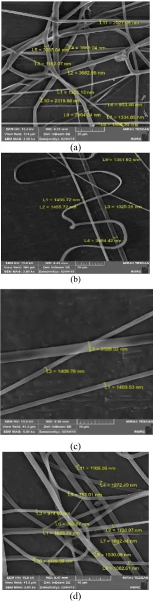
The optimization of the effective parameters on fibers morphology were studied using OM and FE-SEM images (Note that the optimization process was done for polymer/BG ratios of 5:4, 8:4 and 12:4). After the clear transparent sol mixed with PVA and loaded into the syringe, the starting voltage was 6kV with a distance between the needle tip and collector of 9cm, which could not overcome the tension of the sol and subsequently no fibers were obtained, increasing the voltage at the same distance, little by little at the voltage of 8.8kV, the sol formed a jet and resulted in thin fibers. Figure 1 shows the formation and morphology of room temperature dried fibers indicating an obvious reduction in diameter as voltage increased. As the charges carried by the jet as a result of higher voltage increase, higher elongation forces will be imposed to the jet under the electrical field. It has been known that the overall tension in the fibers depend on the self-repulsion of the excess charges on the jet. Therefore, as the charge density increases, the fiber diameter becomes smaller [23].
Figure 1b and 1c show the effect of working distance on the fibers. The reduction in diameter can be observed and seems to be as a result of evaporation of solvent before the fiber is collected on the collector.
In this work, it was observed that the glass fibers could not be fabricated from pure bioactive glass sol, because based on the literature review [18], herein the Si–O network of glass sol did not offer sufficient intermolecular interactions so it was essential to add a carrier polymer with long chains into the glass sol to facilitate the formation of the fibers. The addition of the polymer to the sol, increases the solution viscosity and can affect the fiber morphology during electrospinning [24,25].
(a)
(b)
(c)
(e)
(f)
(g)
Figure 1. FE-SEM images of dried fibers in PVA/BG ratio of 5:4 and flow rate of 0.05 mLh-1 (a) V = 8.8 kV, d = 9cm
(b) V = 11.4 kV, d = 9cm(c) V = 11.4 kV, d = 12cm, PVA/BG ratio of 8:4 and flow rate of 0.1mLh-1 (d) V = 8.8
kV, d = 9cm, (e) V = 15.6 kV, d = 9cm, (f) V = 20 kV, d = 10cm, PVA/BG ratio of 12:4 and flow rate of 0.2mLh-1 (g)
V = 20 kV, d = 10cm.
As it is shown in figure 1(a,d) at 5:4 and 8:4 PVA/BG sol ratios, approximately a bead free, stable fibrous structure was produced. As the PVA/BG sol was increased from 5:4 (Figure 1a) to 8:4 (Figure 1d), an obvious decrease in fibers diameter was observed.
Although the addition of PVA to BG sol led to the increment in the solution viscosity, it improved the solution conductivity and decreased the solution surface tension [13], which was the main reason resulted in a
decrement in the BG fibers diameter. This result is in accordance with the findings of Kim et al. [4]. At higher ratios, some overlapping in fibers and difficulties were noticed during electrospinning in a way that at ratio of 12:4, the effect of viscosity dominates and increases the average diameter of the fibers. The whole results are brought and summarized in Table 1. The lowest average fiber diameter was obtained at PVA/BG sol ratio of 8:4, voltage and working distance of 20 kV and 10 cm respectively, which is reported as optimized sample.
Table 1. The effects of processing parameters and polymer content of BG submicron fibers on average diameter.
PVA/BG sol ratio
voltage (kV)
working distance (air gap) (cm)
average fibers diameter (µm)
5:4 8.8 9 2.199
5:4 11.4 9 1.751
5:4 11.4 12 2.046
8:4 9 9 1.159
8:4 15 9 1.113
8:4 20 10 0.991
12:4 20 10 1.371
As the micrographs show, it seems that in PVA/BG solutions ratio of 8:4 although the fibers diameter decrease by elevating the voltage, the orientation and homogeneity of the fibers are affected. These results show that there is a relative dependency between voltage and working distance on fibers formation. It implicates that for higher voltages in order to achieve well oriented and smooth fibers, the distance needs to be increased.
3.2 Structural characterizations
The XRD pattern of the prepared BG fibers after heating at 600 °C did not contain diffraction maxima, indicative of the internal disorder and the glassy nature of this material (figure 2). The XRD pattern of the sample confirms its amorphous nature, characterized by the broad diffraction bands.
The FT-IR spectrum of calcinated fibers is shown in figure 3. The absorption bands near 879 and 1028 cm-1 can be attributed to the Si-O-Si symmetric and asymmetric stretching vibration as the characteristic peaks of bioactive glass [21]. The bands near 1400-155- 1 are attributed to the carbonate groups and 3747 cm-1 to the hydroxyl groups [22]. The obtained spectrum also verifies the correct selection of calcination temperature since due to the results reported by Deliormanlı [20], by increasing the temperature from 600 to 700 ºC, crystallization will be occurred in the composition.
Figure 3. FTIR spectrum of 58S bioactive glass fibers calcinated at 600ºC.
3.3 Evaluating the effect of calcination
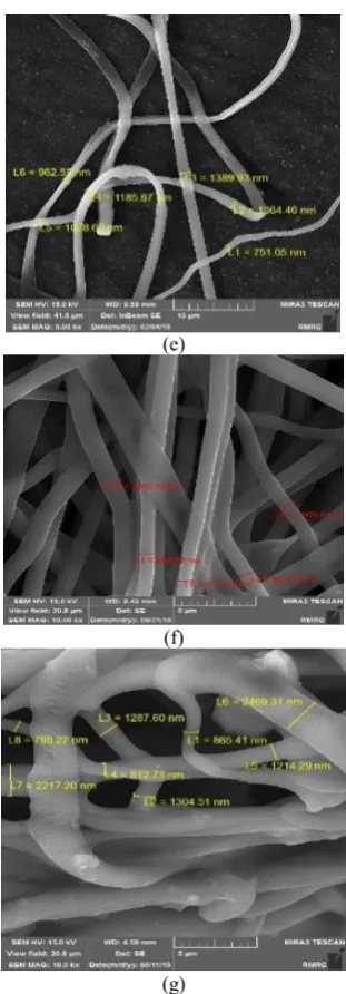
Figure 4(a-c) shows the FE-SEM micrographs of the prepared fibers after heat treatment at 600 ºC. After the PVA was selectively removed by calcination of dried fibers, the BG fibers retained their fibrous nature, while the average diameter was reduced to 0.7 µm for the optimized sample. A little reduction in surface
smoothness occurred due to the polymer
eliminationhowever there were no cracks in the fibers.
(a)
(b)
(c)
Figure 4. FE-SEM images of BG submicron fibers in electrospun in PVA/BG sol ratio of 8:4 and flow rate of 0.1 mLh-1 (a) V = 8.8 kV, d = 9cm (b) V = 15.6 kV, d = 9cm (a)
V = 20 kV, d = 10cm after calcination at 600 ºC for 3h.
()
4. CONCLUSION
REFERENCES
1. Jones J.R., “Review of bioactive glass: From Hench to hybrids”,
Acta Biomaterialia, Vol. 9, (2013),4457–4486.
2. Rahaman M, Day D.E, Bal B.S, Fu Q, Jung S.B, Bonewald L.F, Tomisa A.P, “Bioactive glass in tissue engineering”, Acta Biomaterialia, Vol. 7, (2011), 2355-2373.
3. Hutmacher D. W., Schantz J.T., Fu Lam Ch. X., Tan K. Ch., Lim T. L., “State of the art and future directions of scaffold-based bone engineering from a biomaterials perspective”, Journal of Tissue Engineering and Regenerative Medicine, Vol. 1, (2009), 245-260.
4. Kim, H. W., Kim, H. E., Knowies, C., "Production and Potential of Bioactive Glass Nanofibers as a Next-Generation Biomaterial ", Advanced Functional Materials, Vol. 16, (2006), 1529-1535. 5. Xia W., Zhang D., Chang J., “ Fabrication and biomineralization
of bioactive glass (BG) nanofibres”, Nanotechnology, Vol. 18, No. 13, (2007), 7pp.
6. Huang Zh.M. , Zhang Y. Z.,Kotakic M., Ramakrishna S., “A review on polymer nanofibers by electrospinning and their applications in nanocomposites”, Composites Science and Technology, Vol. 63, (2003), 2223–2253.
7. Ondarcuhu T., Joachim C., “Drawing a single nanofibre over hundreds of microns”, International Journal of Europhysics Letter, Vol. 42, (1998), 215–220.
8. Feng, L., Li, S., Li, H., Zhai, J., Song, Y., Jiang, L., "Super- Hydrophobic Surface of Aligned Polyacrylonitrile Nanofibers",
International Journal Angew Chemical International Edition, Vol. 41, No. 7, (2002), 1221–1223.
9. Martin Ch. R, “Membarane-Based Synthesis of Nanomaterials”,
Chemistry of Materials, Vol. 8, No. 8, (1996), 1739-1746. 10. Ma P. X., Zhang R., Journal of Biomedical Materials Research,
Vol. 46, No. 1, (1999), 60-72.
11. Liu G. J., Ding J. F., Qiao L. J., Guo A., Dymov B. P., Gleeson J. T., “Polystyrene-block-poly(2-cinnamoylethyl methacrylate) Nanofibers-Preparation, Characterization, and Liquid Crystalline Properties” Chemistry-A European Journal, Vol. 5, No. 9, (1999) 2740-2749.
12. Whitesides G. M., Grzybowski B., “”, Science, Vol. 295, No. 5564, (2002), 2418–2421.
13. Deitzel, J. M., Kleinmeyer, J., Hirvonen, J. K., Beck, T. N. C., "Controlled deposition of electrospun poly(ethylene oxide) fibers",Polymer, No. 42, (2001) 8163-8170.
14. Fong H., Reneker D. H., “Electrospinning and formation of nanofibers”, In Structure formation in polymeric fibers, Salem DR, Munich Hanser editions., (2001), p. 225–246.
15. Sigmund W., Yuh J., Park H., Maneeratana V., Pyrgiotakis G., Daga A., Taylor J., Nino J. C., “Processing and Structure Relationships in Electrospinning of Ceramic Fiber Systems”,
Journal of the American Ceramic Society, Vol. 89, issue. 2, (2006), 395-407.
16. Ramaseshan R., Sundarrajan S., Jose R., et al, “Nanostructured ceramics by electrospinning”, Journal of Applied Physics, Vol. 102, (2007), 111101-111117.
17. WU H., PAN W., LIN D., LI H., “Electrospinning of ceramic nanofibers: abrication, assembly and applications”, Journal of Advanced Ceramics, Vol. 1, No. 1, (2012), 2-23.
18. Dong H., Nyame V., Macdiarmid A. G., Jones, W. E. “Polyaniline/poly(methyl methacrylate) coaxial fibers: the fabrication and effects of the solution properties on the morphology of electrospun core fibers”, Journal of Polymer Science Part B: Polymer Physics, Vol. 42, No. 21, (2004), 3934-3942.
19. Jia Y. T., Gong J., Gu X. H., Kim H. Y., Dong J., Shen X. Y., “Fabrication and Characterization of poly (vinyl alcohol)/chitosan blend nanofibers produced by electrospinning method”,
Carbohydrate Polymers, Vol. 67, (2007), 403–409.
20. Deliormanli, A. M., "Preparation and in vitro characterization of electrospun 45S5 bioactive glass nanofibers", Ceramics International, (2015), 417-425.
21. Lu H., Zhang T., Wang X. P., Fang Q. F., "Electrospun submicron bioactive glass fibers for bone tissue scaffold", Journal of Materials Science.: Materials Medicine, Vol. 20, (2008), 793-798.
22. Ghaebipanah N., Alizade P., Eftekkhari Yekta B., “Synthesis of mesoporous glass nanobiofibers with high Surface area by electrospinning”, Journal of Ceramic Science & Engineering,
Vol. 2, No. 3, (2013), 29-37.
23. Mckee, M. G., Layman, J. M., Cashion, M. P., Long, T. E., "Phospholipid Nonwoven Electrospun Membranes", Science, (2006), 311–353.
24. Frenot A., Chronakis I. S., “Polymer nanofibers assembled by electrospinning”, Current Opinion in Colloid & Interface Science, Vol. 8, Issue 1, (2003), 64–75.
25. Dai H., Gong J., Kim H., Lee D., “A Novel method for preparing ultra-fine alumina-borate oxide fibers via an electrospinning technique”, Nanotechnology. 2002, 13, 674–677.