Reflection halo twins: subsun and supersun
Gunther P. Können
1,* and Siebren Y. van der Werf
2 1Sophialaan 4, NL-3761DK Soest, The Netherlands2Kernfysisch Versneller Instituut, University of Groningen, Zernikelaan 25, NL-9747 AA Groningen, The Netherlands
*Corresponding author: [email protected]
Received 2 May 2011; revised 27 July 2011; accepted 31 July 2011; posted 1 August 2011 (Doc. ID 146958); published 21 September 2011
From an aircraft, a short distinct vertical structure is sometimes seen above the setting sun. Such a feature can be understood as a halo, which is the counterpart of the well-known subsun. Whereas the latter arises from reflections off basal faces of plate-oriented ice crystals illuminated from above, what we call the supersun emerges when these crystals are illuminated from below. The supersun occurs when the sun is below the true horizon and is only visible from elevated positions. The curvature of the Earth causes the ensemble of reflecting crystal faces to act as a hollow mirror and the supersun appears as a vertical band of uniform width, extending from the sun upwards to its supersolar point. We discuss the geometrical properties of the phenomenon and simulate its shape and radiance distribution with an extended version of an atmospheric ray-tracing program. © 2011 Optical Society of America
OCIS codes: 010.2940, 010.1290, 010.1310, 290.5850.
1. Introduction
Figure1shows what on first inspection resembles a vertically elongated mirror image of the sun, with its center at2°:1above the upper rim of the setting sun. The phenomenon appeared during a 1 h50min flight from Oslo to Kirkenes, in the far northeast of Norway (69°460N, 30°50E), on 10 September 2008. Takeoff was at 16:30 UTC; 1 hour later the aircraft flew through a cold front whose clouds extended to the level of the aircraft. Just before the aircraft entered the clear sky behind the front, a bright parhelion appeared (Fig. 2), proving the presence of plate-oriented ice crystals in the frontal clouds. Sunset,
75min after takeoff and15min after the frontal pas-sage, took place in the receding cloud layer of the just-passed front, which by then was 150km away. The apparent angular height of the frontal cloud layer was estimated from the photo to be3°:2, in ac-cordance with the value of the horizon dip of3°:3for
12km altitude. Two pictures of the setting sun with the feature above it were taken. From these, the width of the spot was found to be0°:5, equal to the
sun’s diameter within the uncertainty. The spot’s ver-tical dimension was0°:8; it extended from1°:8to2°:6 above the upper limb of the sun, which was about
0°:1 above the apparent horizon, the latter being by definition the direction in which the edge between sea and sky is seen from an elevated position. Closer inspection of Fig.1reveals that an upward extension of the spot is still perceptible up to the top of the cloud layer.
Despite the elongated shape, the observed feature does not seem to be an ordinary pillar and our attempts to simulate it as such with Cowley and Schroeder’s HaloSim program [1] failed to ade-quately reproduce its distinct shape and uniform width.
We interpret this feature as due to the reflection of sunlight from the horizontally oriented faces of plate-oriented airborne ice crystals, just like in the case of the subsun. With the sun below the true hor-izon (i.e., the locally horhor-izontal direction), even a per-fectly horizontal crystal face can be illuminated from below, which creates a mirror image above the sun. The image of the resulting halo is, however, not a simple inversion of that of the subsun: due to the curvature of the Earth, the reflecting basal faces of distant plate-oriented crystals are not parallel with
the aircraft’s horizontal, but instead with respect to their own local horizontals. In this scattering geome-try, the Spin Vector Assumption [2,3] is not satisfied in the line of sight of the observer and the ensemble of crystal basal faces acts as a hollow fun house mirror, causing the reflected image to appear as a distinct vertical band of uniform width extending up-wards to the supersolar point—which is the point di-rectly above the sun, equally high above the aircraft’s true horizon as the sun is below it.
To our knowledge, the effect of the Earth’s round-ness on the appearance of horizon halos or near-horizon halo segments has not been discussed before. The above-mentioned observation inspired us to do a quantitative analysis of the shape and radiance
distributions of halos due to reflection at horizontally oriented crystal faces for the sun on either side of the horizontal. For positive solar altitudes and a flat Earth, this halo appears as the reflection of the sun’s image across the horizontal and is known as the sub-sun. Traditionally, the term “subsun” refers to the situation where the sun is above the horizontal, but due to the Earth’s curvature this reflection halo can also develop below the sun when the latter is be-low the horizontal but still visible above a dipped horizon. To avoid proliferation of terminology, we will call this extension by the same name: the subsun. Emphasis, however, in the present paper will be on the feature that develops above the sun for negative sun altitudes. It can be regarded as a deformed coun-terpart of the usual subsun, and we will name it by its corresponding Latin prefix: the supersun [4].
2. Geometry of Subsun/Supersun Formation for a Round Earth
A. General Considerations
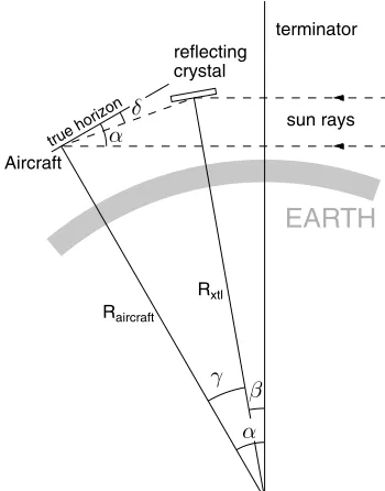
The geometry of the problem is depicted in Fig. 3.
RaircraftandRxtlare the distances to the Earth’s cen-ter of the aircraft and of the reflecting crystal, respec-tively.αandβare the sun’s depression angles as seen from the aircraft and from the reflecting crystal: the sun’s angular distance below the true horizon of these respective locations. At the same time,αis the angular distance between the aircraft’s geographical position and the terminator of the Earth, which is po-sitive when the sun is below the horizontal. Likewise, βis the angular distance between the reflecting crys-tal and the terminator. The angleγ, which measures the angular distance between the geographical posi-tions of the aircraft and the reflecting crystal, equals the tilt angle of the reflecting crystal basal face with respect to the aircraft’s true horizontal. γ is always
Fig. 1. (Color online) Vertically elongated structure above the sun. It extends upwards to2°:6above the sun and has a width of 0°:5. The sun is setting behind the apparent horizon, which is3°:3 below the true horizon. The horizontal field of view of the picture is13°. Photograph taken on 10 September 2008 at 17:46 UTC by G.P. Können on a flight from Oslo to Kirkenes (Norway) from a height of12km.
Fig. 2. (Color online) Parhelion, photographed during the pas-sage through the frontal clouds. The appearance of this halo proves that horizontally oriented crystal faces were present in the frontal clouds in which the vertical feature of Fig.1appeared14min later. The horizontal field of view of the picture is21°. Photograph taken on 10 September 2008 at 17:32 UTC by G.P. Können.
true horizon
Aircraft
reflecting crystal
terminator
sun rays
Raircraft
Rxtl
EARTH
positive. From the aircraft, the reflecting crystal is viewed at a (positive or negative) depression angle δ. For the observer, the crystal creates a light point on the celestial sphere, called a halo point [2]; the to-tal of the halo points of all reflecting crysto-tals makes up the halo. For the moment, we ignore the effect of refraction and consider the rays as perfectly straight lines. Inspection of Fig.3 shows
β¼α−γ ð1Þ
and
δ¼α−2β¼−αþ2γ ð2Þ
and
Rxtl¼Raircraft
cosðδÞ
cosðβÞ¼Raircraft
cosðα−2γÞ
cosðα−γÞ : ð3Þ We insert in this expressionhxtl≡Rxtl−REarth, being
the height of the reflecting crystal above the Earth, and h0≡Raircraft−REarth, the height of the aircraft
above the Earth—also called the flight level of the aircraft. Then Eq. (3) modifies to
hxtlðγÞ ¼h0−2Raircraft
cosð1
2γÞsin½12ð2α−3γÞ
cosðα−γÞ : ð4Þ
For a fixed solar depression angle,α, Eq. (3) gives the general expression for the locus of the reflecting crys-tals, which contribute to the image the observer gets to see. It is valid for negative (α>0) as well as for positive (α<0) sun altitudes. Equation (3) shows that the locus starts (atγ¼0) at the aircraft’s flight level, where the reflecting crystals surrounding the aircraft create a halo point at the subsolar (for α<0) or supersolar point (for α>0). Equation (4) shows that the height of the locus above the aircraft’s flight level,hxtlðγÞ−h0, is virtually independent ofh0, as Raircraft equals REarth, the radius of the Earth, within 0.02%. Figure4illustrates how, for a negative sun altitude, the part of the locus above the night side of the Earth produces a supersun and the part above the daylight side a subsun. As already
men-tioned in Section 1, the roundness of the Earth
extends the regime of sun altitudes where the subsun may occur all the way down to the observer’s dipped horizon. Figure4shows how, for negative sun heights but still above the apparent horizon, the supersun and the subsun may both be seen at the same time—where visually the latter appears as the down-ward continuation of the former.
According to Eq. (3), the locus would extend all the way down from the aircraft’s position (γ¼0) to the center of the Earth (δ¼90°, or γ¼45°þα=2). But obviously only the part of the locus above the Earth’s surface contributes. This sets an upper limit on γ, which is found by puttinghxtlequal to zero in Eq. (4). Supersun-creating sun rays all have to travel past the terminator before they hit a crystal. They reach their minimum distance from the Earth’s center,
Rmin, straight over the terminator (see Fig.3). From the figure and Eq. (3), it follows thatRminis given by
Rmin¼RaircraftcosðδÞ; ð5Þ
so that Rmin<Raircraft for any δ≠0. This implies
that for a ground-based observer (Raircraft¼REarth)
all supersun-making sun rays are blocked by the Earth. Consequently, a supersun or a segment of it can only be observed by an observer flying in the air or standing at an elevated position.
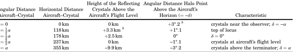
Table 1 lists five special points on the locus to-gether with their numerical values forα¼3°:2, cor-responding to the situation as photographed (Fig.1). The first of these points isγ¼0, which is the obser-ver’s position, where the ice crystals immediately in front of him create the supersun’s upper edge. The last of the five points is γ¼α, which corresponds to the lower edge of the supersun. Halfway between aircraft and terminator, at γ¼1
2α, the contributing crystals are viewed on the observer’s true horizon. The locus reaches its highest point above the air-craft’s flight level forγ¼1
3αand crosses the flight le-vel again at γ¼2
3α. Because an aircraft’s typical cruise altitude (≈12km) is usually well above the cloud tops, the most relevant region ofγis the inter-val½2
3α;α, where the reflected light comes from crys-tals floating below the aircraft’s flight level. This segment of the supersun, which is still entirely below the true horizon, is what is most often observable for an air passenger.
B. Restrictions on the Supersun’s Appearance
A first restriction applies to the sun altitude. A supersun can only appear when the crystals are illuminated from below. Since angles are counted as positive from the true horizon downward in Fig.3, this condition meansβ>0, or, by Eq. (1), thatγ<α. As γ is always counted positive in the observer’s
viewing direction, this situation can only occur when α>0, a positive solar depression angle, hence a ne-gative sun altitude. Conversely, when the sun has a positive altitude (α<0), a subsun may be seen via reflections off the top faces of the crystals, described by β<0.
A second restriction applies to the length of the supersun. From Eq. (2) follows that the supersun ex-tends from the direct image of the sun, whereβ¼0, henceδ¼α, upwards to the supersolar point, a dis-tance of 2α above it that corresponds to reflections immediately in front of the observer: γ¼0, where δ¼−α. This restriction applies as long as the sun is seen above the apparent horizon. For an aircraft at 12km height, the horizon dip amounts to 3°310
without refraction, or3°190when atmospheric refrac-tion is included. When the sun is below the apparent horizon,α>dip and the supersun is naturally seen only from the apparent horizon upwards. It can ea-sily be understood that it is then also cut off from above at a height that corresponds to the“mirror hor-izon,”that is, a distance equal to the dip above the true horizon.
A third restriction is introduced when the presence of ice crystals is limited to a certain region between a lower and an upper height above the ground. Writing as before hxtl≡Rxtl−REarth and h0≡Raircraft−REarth,
Eq. (4) gives to leading order
γð2α−3γÞ ¼
δþα
2
α−3δ
2
≈2ðhxtl−h0Þ
REarth ; ð6Þ
which is rewritten as
α¼δ ffiffiffiffiffiffiffiffiffiffiffiffiffiffiffiffiffiffiffiffiffiffiffiffiffiffiffiffiffiffiffiffiffiffiffiffiffiffiffiffiffiffiffiffiffiffiffiffiffiffiδ2þ2ðh
xtl−h0Þ=REarth
q
: ð7Þ
This is a hyperbola in the plane ofδversusα, whose shape depends on the crystal height minus the air-craft height, hxtl−h0.
C. Ray Tracing
These three geometrical restrictions on the image of the supersun, and at the same time that of the subsun, are illustrated by a ray tracing calcula-tion (Fig.5).
From the position of the observer, 12km above the Earth, rays are followed to the right. The
procedure has been described in earlier publications [5–7]. Consistent with the foregoing discussion, we neglect refraction for the moment. The integration is done by path length, as described in [7], and after each integration step a random number rndð1Þfrom a uniform distribution between 0 and 1, is generated to decide whether or not to attribute a reflection to the ray at that point.
The probability of a reflection taking place must scale with the area that the crystal presents at right angles with the incoming ray. The observer views the crystal under an angle β, as defined in Fig. 3. Accordingly, we adopt the criterion
rndð1ÞjsinðβÞj<ds=λ0→reflection;
rndð1ÞjsinðβÞj≥ds=λ0→no reflection; ð8Þ
where ds is the integration step size andλ0defines a mean free path length.
Rays are calculated for observed angles from−15° to þ15° in steps of 00:01. The mean free path is adjusted such that the number of rays with
0;1;2;… reflections decreases by about a factor of 10 for each additional reflection. On a fundamental note, including reflections of all orders anda poster-iori selecting the ensemble of single reflections re-spects time reversal invariance and therewith the procedure of doing ray tracing backwards. A forced limitation to zero or one reflections, on the other
horizontal distance (0-1800km)
surface of the Earth
elevation (0-85km)
Fig. 5. Ray tracing for subsun/supersun simulation. The rays are traced backward from the observer until they reach the upper mesosphere. Because the Earth’s surface is drawn as a straight line, all light rays bend upward. A kink indicates the place where a ray is reflected by a horizontally oriented crystal face.
Table 1. Special Points on the Reflection Locus for Sun Depressionα3°:2a
Angular Distance Aircraft–Crystal
Horizontal Distance Aircraft–Crystal
Height of the Reflecting Crystals Above the Aircraft’s Flight Level
Angular Distance Halo Point Above the Aircraft’s
Horizon (¼−δ) Characteristic
γ¼0 0km 0km þ3°:2b crystals near the observer;δ¼−α
γ¼1
3α 118km þ3:3km
b
þ1°:1 top of locus
γ¼1
2α 178km þ2:5km 0° δ¼0°
γ¼2
3α 237km 0km −1°:1 crystals at aircraft’s flight level γ¼α 355km −9:9km −3°:2 crystals above the terminator;δ¼α
aSun taken as a point source. As in Eqs. (1)
–(4) and (6), on which this table is based, refraction is ignored.
hand, would make the single-reflection ensembles differ for forward and backward ray tracing.
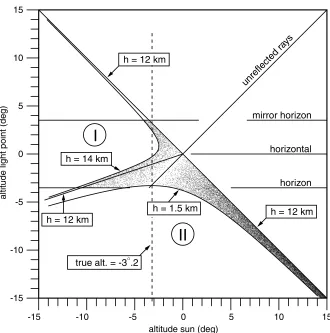
The scatter plot of single reflections is shown in Fig. 6. It constitutes a cloud of points in the plane of the observed altitude of the light points (−δ) versus the altitude of the sun (−α), taken as a point source. The subsun and the supersun, though described by the same mathematical form of their locus, are dis-tinct phenomena and the density of the points drops to zero on both sides of the diagonal line that sepa-rates them.
The three restrictions formulated above appear naturally:
1. For small solar depression angles, the super-sun ranges from the super-sun itself, on the diagonal, to the antidiagonal, which is its mirror across the true horizontal.
2. For larger depression angles, the supersun is cut off at the apparent horizon on its lower side and by the mirror horizon from above.
3. The limits imposed by the height of the crys-tals as found from Eq. (7) show up as hyperbolic curves. The upper limit is taken here as14km above the Earth and the corresponding hyperbola lies in the sector to the left, indicated by I. The lower limit
for the ice crystals is taken as1:5km, and produces a hyperbola in sector II. The latter limits the scatter plot both for the supersun and the subsun. For
h¼h0¼12km, both hyperbola’s have shrunk to their asymptotic lines, showing once more that the antidiagonal itself bounds the scatter plot.
An additional restriction arises when the front of the ice crystals begins at some distance away from the observer. In that case, an additional region below the antidiagonal and parallel to it is blanked out. This has not been indicated in Fig.6.
The dashed vertical line in Fig. 6 indicates the altitude of the sun as it was in the situation when the photograph in Fig.1was taken. This is the region where the locus [Eq. (3)] rises above the adopted limit of 14km; see also Table 1. As a consequence, the supersun shows itself in two parts, with a darker zone in between.
3. Radiance Distributions of the Subsun and the Supersun
A realistic ray-tracing analysis of near-horizon phenomena must include atmospheric refraction, loss of intensity by reflections off the ice crystals, and atmospheric extinction. We chose the US1976
horizon horizontal mirror horizon unreflected
rays
h = 1.5 km h = 12 km
h = 14 km
h = 12 km
h = 12 km
I
II
-15 -10 -5 0 5 10 15
altitude sun (deg) -15
-10 -5 0 5 10 15
altitude light point (deg)
true alt. = -3 .2
standard atmosphere [8] and performed the analysis as described above, by calculating rays for apparent altitudes between−15° andþ15° in steps of00:01. Re-fraction and air mass are calculated as path integrals [7] and stored, after which a (true) sun altitude can be chosen and those rays selected that happen to hit the sun disk on their outgoing path.
A. Refraction and Geometry
Atmospheric refraction makes the horizon dip as seen from the12km flight level decrease from3°310
to 3°190. At the horizon, refraction for unreflected rays amounts to620, and the true altitude is−4°210. The diagonal in Fig.6, which is the locus of the direct sun in this figure, gets a little curved just above the horizon and the same curvature shows up in the anti-diagonal, which is its mirrored shape. Also, the boundaries imposed by restricting the ice crystals to a height interval between 1.5 and 14km are no longer the perfect hyperbolas of Eq. (7), but still re-semble them closely.
All geometric considerations of the previous section remain valid and the resulting shape of the scatter plot for single reflections closely resembles that of Fig. 6.
B. Intensity Loss at Reflection
Reflections from horizontally oriented crystal faces occur in the ray-tracing calculation via the randomi-zation procedure described in Section 2. For each such reflection, the Fresnel coefficient for external reflection,R, is evaluated. Light may, however, also be reflected under the same angle via one or more internal reflections within a crystal. In Tape’s nota-tion [9], this may occur via ray paths 326 and 316 for the subsun and the supersun, respectively. These in-ternal reflection modes add to the exin-ternal reflection and an appropriate estimate for the total reflectance is 12ð1þRÞ, rather than R. The effect of this re-placement is, however, small: in the range of sun altitudes studied here, the crystals’ tilt angles are
always small enough to make R>0:8, hence
1
2ð1þRÞ>0:9.
C. Atmospheric Extinction
The radiance or brightness of the supersun scales with a geometric factor sinðβÞand with the total re-flectance. In addition, the radiance distribution is af-fected by extinction and the latter is found to be the governing factor. The reason is that within its angu-lar range from the subhorizontal sun to its superso-lar point, the path length of the rays through the atmosphere varies in an extremely drastic manner. Extinction may be described by the Lambert–Beer law as
lnðIÞ−lnðI0Þ ¼−bX=X0; ð9Þ whereXis the air mass along the light’s path;X0is a standard air mass, or optical depth, calculated for a vertical path to the zenith above sea level; andb is
the extinction coefficient. Astronomers usually re-write the Lambert–Beer law in terms of stellar mag-nitudes, in which form it is known as Bouguer’s law:
m−m0≡2:5½log10ðI0Þ−log10ðIÞ ¼kX=X0; ð10Þ where
k≡2:5log10ðeÞb¼1:08574b ð11Þ is the extinction coefficient if expressed on the stellar magnitude scale. For an idealized Rayleigh atmo-sphere, k¼0:1054 for visible light of λ¼550nm. Mie scattering by aerosols and absorption, mostly by ozone, increases the extinction and at sea level, a value ofk≈0:25is more typical [10]. From a survey of different observatories [11],k≈0:15seems appro-priate for circumstances of very good visibility [12–15]. We will adopt this value for our analysis and discuss the consequences of our choice at the end of the next subsection.
D. Results
Figure7shows how the relative air mass varies with the observed altitude within the ensemble of the about 20,000 rays that have suffered one single re-flection for an aircraft at flight level 12km looking
at a cloud of crystals between 1.5 and 14km in
height. All conceivable solar heights resulting in a halo point of the super/subsun between altitude −15° and the mirror horizon cutoff ofþ3°:3are con-sidered. The subsun is seen to have its strongest ex-tinction on the apparent horizon, at−3°:3. The most prominent feature of Fig.7is, however, the extremely strong angle dependence for the supersun, which shows a deep minimum, and thus a minimal extinc-tion, right on the true horizon.
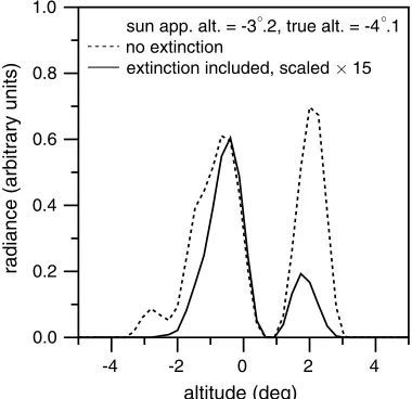
The radiance distribution as calculated for the situation under study is shown in Fig. 8. The sun is at −3°:2, just above the apparent horizon. The distribution has two maxima, separated by a
minimum around an altitude of 1°. This minimum
0 50 100 150
relative
air
m
ass
-14 -12 -10 -8 -6 -4 -2 0 2 4
altitude halo point (deg) aircraft height = 12 km ice crystals:
hmin= 1.5 km, hmax= 14 km
subsun
supersun
Fig. 7. Relative air massX=X0for the calculated single-reflection
is due to the fact that here the reflection locus rises
until above 14km, which was adopted as an upper
limit for the ice crystals. The introduction of an upper boundary lower than the locus’s top eliminates a segment of the supersun centered just above the air-craft’s true horizon (see the second special point of Table 1). This effect is also apparent from Fig. 6, where near altitude ∼1°, the vertical line drawn at
3°:2passes through a region void of dots. Extinction is seen to reduce the above-horizon peak (centered at altitude þ2°) much stronger than the subhorizon one (centered at −2°), because the latter is closer to the true horizon (0°). Thus, while geometrically the supersun should range from −3°:2 to þ3°:2, its brightness is mainly concentrated in a relatively nar-row region, just below the true horizon. This agrees remarkably well with the observation of an elongated spot, extending from 1°:8 to 2°:6 above the sun’s upper limb (see Section 1).
Figure 9 presents the radiance distributions for different sun heights in a way similar to Fig.6. As mentioned earlier, the inclusion of atmospheric re-fraction leaves the global geometric features largely unchanged. The calculated brightness distributions in Fig.9have been obtained by a horizontal binning
0.0 0.2 0.4 0.6 0.8 1.0
radiance
(arbitrary
units)
-4 -2 0 2 4
altitude (deg)
sun app. alt. = -3 .2, true alt. = -4 .1 no extinction
extinction included, scaled 15
Fig. 8. Radiance distribution of the supersun as a function of altitude, as seen from a flight level of12km, with the sun just above the3°:3dipped apparent horizon. The dashed line neglects atmospheric extinction, while for the15× scaled-up solid line it is included.
in intervals, equal in width to the sun’s diameter,
320. Radiance is visualized by a gray value,
rgb255ðg;g;gÞ, whereg is taken proportional to the calculated (stellar) magnitude [Eq. (10)]. The maxi-mum radiance in the simulation is associated with
g¼255(white) and 0 (black) is made to correspond to a lower radiance, different from the maximum by 10 stellar magnitudes. The maximum radiance en-countered in the subsun region is much larger than that in the supersun region. For reasons of presenta-tion, we have therefore done this“gray tone calibra-tion”in both regimes separately, assigning in each of them white to their maximum brightness and black to a brightness that is 10 stellar magnitudes lower. Besides being convenient, the presentation of radiances on a logarithmic scale is justified by Fechner’s law [16], which states that we perceive the intensity of stimuli on a logarithmic rather than a linear scale.
For the presentation of Fig.9, we have chosen an extinction coefficient k¼0:15 and a span of 10 in stellar magnitude between white and black. Might
someone find this k value too small, then he may
imagine the figure to have been made for a higher
k, with the span in magnitude increased accordingly. We acknowledge that our computer simula-tions will never be able to give a full match with the radiance distribution of the observed feature (Fig.1) because the extinction by clouds in the frontal systems and its blocking of incoming light to the crys-tals cannot be modeled. Nevertheless, quantitative agreement between observation and calculation emerges, which provides some confidence in the in-terpretation of Fig. 1 being indeed a picture of the supersun.
4. Discussion and Conclusion
A. Conditions for Observing the Supersun
A supersun above the setting sun may also be visible from heights lower than the aircraft’s cruise height. The primary condition for its formation is that the sun must be below the true horizon. With the sun at the apparent horizon, the full extension range of the supersun equals twice the value of the horizon dip. So for a mountain-based observer (1000m), the maximum length of the supersun is1°:9, while for a tower-based observer (100m)0°:6and for an obser-ver standing on a dune near the beach (10m), it is
0°:2. An observer standing at ground level will never see the supersun, as the light path sun-crystal will always be blocked by the surface of the Earth.
These above-mentioned ranges are the geometrical limits of the length of the supersun. Within these ranges, extinction in the total light path is minimal for halo points appearing at the true horizon, so that even for fully developed supersuns, a maximum in brightness will appear in a region around altitude0°. Full development of the supersun requires that the observer is surrounded by crystals, that the sun is about to set, and that the crystal layer reaches higher
than the maximal height of the locus of reflect-ing crystals (second special point of Table 1). For mountain-based observers, the first and last require-ments are easier fulfilled than for high-flying jets, so mountaineers may more often encounter a fully de-veloped supersun. For near-ground-based or tower-based observers living outside the polar regions, the observation will be much rarer, as even in winter time they will only very rarely be surrounded by crys-tals. However, tower-based observers living in cold climates may occasionally encounter this feature in full development.
B. Supersun Versus Pillar
Imperfectness in the orientation of the plate-orientation increases the length of the supersun: a dispersion of, e.g.,1° in the tilt angle of the crystals causes it to extend to2° above the supersolar point. This is easily verified by our ray-tracing program when a wobble in the crystal’s orientation is added via a random Gaussian variable. This result implies that the mirror horizon no longer cuts off the super-sun from above. Seen from an aircraft, the2° stretch of the supersun is, however, still small compared to its length, which under idealized conditions is6°. The resulting phenomenon can still be regarded as a stretched supersun. However, seen from a tower from which the supersun’s length is only 0°:6, a plate or-ientation that is tenfold better is needed to keep the supersun at the same level of recognizability as from an aircraft. Hence, the larger the wobble of the crystals or the lower the observer’s altitude, the more the supersun is stretched relative to its length under idealized conditions and the less its typical features can be recognized. At some stage, one would be inclined to call the phenomenon a pillar; this hap-pens when the effect of the Earth’s curvature on the shape of the feature starts to become small relative to the effect of imperfections in the crystal orientation. In fact, the distinction between the supersun and the pillar is not sharp but it is a sliding scale, based on the degree of perfection in the orientation of the ice crystals.
name also when a dispersion in the crystal’s orienta-tions produces a pillar above it.
C. Relation with the Parhelic Circle
There exists a similarity between the supersun and the parhelic circle, in the sense that the supersun can be regarded as a segment of a rotated parhelic circle—one that passes through sun and zenith [17]. Both halo forms can be ascribed to reflecting crystal faces that have a freedom to rotate about a fixed axis in space: vertical for the parhelic circle, horizontal and perpendicular to the plane sun–zenith–observer for the supersun. The difference is that the degree of freedom to rotate is restricted in the case of the supersun so that only a short segment of this“ verti-cal parhelic circle”shows up.
D. Deformation of Other Halos
The curvature of the Earth may affect the shapes or positions of halos other than the subsun, among them the parhelia and the subparhelion. Near-horizon parhelia formed in high clouds may even for ground-based observers show a downward dis-placement of maximally 0°:2—small, but perhaps perceivable if the parhelion appears above a well-defined horizon, e.g., over the sea. A subparhelion, on the other hand, would strongly deform into a fea-ture similar to the supersun: for an elevated observer and the sun below the true horizon, it transforms into a vertical band at22° left or right from the sun, extending from the (dipped) apparent horizon to the mirror horizon. Reports of this phenomenon are lacking, although a recent picture by Hinz [18] taken at a sun altitude of−1°:8from the top of the1835m Mount Wendelstein contains a possible hint of it.
The authors thank Piet Stammes, Jan Willem Pel, and Sergey Kivalov for many discussions on the topic of atmospheric extinction.
References and Notes
1. L. Cowley and M. Schroeder, HaloSim3 Software,http://www .atoptics.co.uk/halo/halfeat.htm.
2. W. Tape and G. P. Können,“A general setting for halo theory,” Appl. Opt.38, 1552–1625 (1999).
3. G. P. Können, “Symmetry in halo displays and sym-metry in halo-making crystals,” Appl. Opt. 42, 318–331 (2003).
4. In German the subsun is known as the“Untersonne,”and “Übersonne”would be the appropriate translation for super-sun. In French, the“sub-soleil”or“soleil inferieur”would find their logical counterparts in“super-soleil”and“soleil super-ieur.”In Dutch the subsun is called“onderzon”and the super-sun will be the“bovenzon.”
5. S. Y. van der Werf,“Ray tracing and refraction in the modified US1976 atmosphere,”Appl. Opt.42, 354–366 (2003). 6. S. Y. van der Werf, G. P. Können, and W. H. Lehn,“Novaya
Zemlya effect and sunsets,”Appl. Opt.42, 367–378 (2003). 7. S. Y. van der Werf,“Comment on‘Improved ray tracing air
mass numbers model,’”Appl. Opt.47, 153–156 (2008). 8. D. R. Lide, Handbook of Chemistry and Physics, 81st ed.
(CRC, 2000).
9. W. Tape, Atmospheric Halos, Antarctic Research Series (American Geophysical Union, 1994), Vol. 64.
10. Astronomical observatories often document values ofkper amount of air mass relative to their own unit air mass above the site of the observatory,Xobs, instead of the unit air mass at sea level,X0. This must be kept in mind when comparing
extinction parameters for different observatories.
11. A. Meinel and M. Meinel, Sunsets, Twilights and Evening Skies(Cambridge University, 1983).
12. H. Tüg,“Measurements of the energy distributions of south-ern standard stars from3200Å to8800Å,”Astron. Astrophys. 82, 195–202 (1980).
13. M. Golay,Introduction to Astronomical Photometry(Reidel, 1974).
14. V. B. Nikonov, “Methods of Investigating Variable Stars,” (NASA Technical Translation TT-F-797, Washington, 1973). 15. P. Wang, W. H. Knap, P. Kuipers Munneke, and P. Stammes,
“Clear-sky shortwave radiative closure for the Cabauw Baseline Surface Radiation Network site, the Netherlands,” J. Geophys. Res.114, D14206 (2009).
16. G. T. Fechner, Elemente der Psychophysik (Breidkopf und Härtel, 1860), Vol. II, Chap. 16, English translation from the 1912 edition,http://psychclassics.yorku.ca/Fechner/. 17. K. Hariti,“Parhelic circle over the Dead Sea,”Atmospheric
Optics (2007),http://www.atoptics.co.uk/halo/parcirc.htm. 18. C. Hinz,“Upper parhelia over the Alps,”Ice Crystal Holos