1 1
COMPUTER ORGANIZATION
•
The computer organization is defined by its
–
Its internal registers,
–
the time and control structure, and
–
the set of
instructions
that it uses.
•
Alternatively
–
A digital system is defined by the
sequence
of microoperations it performed on data stored
in its registers
•
A computer runs a
program
and a program is a set of
instructions
which
specify
–
the operations,
–
operands, and
–
the sequence by which processing has to occur
.
•
A computer
instruction
is a
binary code
that specifies a sequence of
microoperations for the computer.
•
Instruction codes
together with
data
are stored in memory.
•
The computer reads each instruction from memory and places it in a
control
register
.
2 2
3 3
THE BASIC COMPUTER
•
The
Basic
Computer has two components, a
processor
and
memory
•
The memory has 4096 words in it
–
4096 = 2
12, so it takes 12 bits to select a word in memory
•
Each word is 16 bits long
CPU
RAM
0 4095 0 15 Memory 4096 ×16Computers have a single- processor register
(
accumulator or AC
) and is used to perform the
operation with memory operand and the content of AC
Instructions (program)
4 4
INSTRUCTION
S
Instruction codes
•
Program
–
A sequence of (machine) instructions
•
(Machine)
Instruction
–
A group of bits that tell the computer to perform a
specific operation
(a
sequence of micro-operations)
•
The instructions of a program, along with any needed data are
stored in memory
•
The CPU reads the next instruction from memory
•
It is placed in an Instruction Register (
IR
) (Control Register)
•
Control circuitry in control unit then translates the
instruction
into
5 5
INSTRUCTION FORMAT
Instruction codes
•
A computer instruction is often divided into two parts (two
fields
)
–
An
opcode
(Operation Code) that specifies the operation for that instruction
–
An
address
that specifies the registers and/or locations in memory to use for
that operation
•
In the
Basic Computer
, since the memory contains 4096 (= 2
12
)
words, we needs 12 bit to specify which memory address this
instruction will use
•
In the
Basic Computer
, bit 15 of the instruction specifies the
addressing mode
(0:
direct addressing
, 1:
indirect addressing
)
•
Since the memory words, and hence the instructions, are 16 bits
long, that leaves 3 bits for the instruction’s
opcode
Opcode
AddressInstruction Format
15 14 12 0
6 6
BASIC COMPUTER REGISTERS
List of BC Registers and their functions
DR 16 Data Register
Holds memory operand
AR 12 Address Register Holds address for memory
AC 16 Accumulator
Processor register
IR
16 Instruction Register Holds instruction code
PC 12 Program Counter Holds address of instruction
TR 16 Temporary Register Holds temporary data
INPR 8 Input Register Holds input character
OUTR 8
Output Register Holds output character
Registers
Registers in the
Basic
Computer
11 0
PC
15 0IR
15 0TR
7 0OUTR
15 0DR
15 0AC
11 0AR
INPR
0 7Memory
4096 x 16
CPU
7 7
INSTRUCTION SET COMPLETENESS
• Instruction Types
A computer should have a set of instructions so that the user can
construct machine language programs to evaluate any
function
that is known to be
computable
.
Functional Instructions
- Arithmetic, logic, and shift instructions
–
ADD, CMA, INC, CIR, CIL, AND, CLA
Data Transfer Instructions
- Data transfers between the main memory
and the processor registers
–
LDA, STA
Program Control Instructions, which change the sequence in which
programs are executed
- Program sequencing and control instructions
–
BUN, BSA, ISZ (
Increment and skip if zero
)
Input/Output Instructions, which cause information to be transferred
between the processor or its main memory and external
devices
- Input and output
–
INP, OUT
9 9
INSTRUCTION SET COMPLETENESS CONTINUED …
•
A typical
machine instruction
defines one or two
register transfer
operations
, and a
sequence
of such machine instructions is needed to
implement a statement in a
high-level language
.
•
The following requirements should be satisfied by an instruction set:
–
It should be
complete
in the sense that one should be able to construct
a
machine-language program
to evaluate any function that is
computable
using a reasonable amount of memory.
–
The instruction set should be
efficient
in that frequently required
function can be performed rapidly using relatively few instructions.
–
It should be
regular
in that the instruction set should contain
expected
opcodes
and
addressing modes
, e.g., if there is a left shift, there should
be a right shift. The instruction set should also be reasonably
orthogonal
with respect to the
addressing modes (
If all actions are
defined for all data types, the instruction set is orthogonal
)
.
–
To reduce both hardware and software design costs, the instructions
10 10
INSTRUCTION SET COMPLETENESS CONTINUED …
•
Completeness
–
A
function
is defined to be
computable
if it can be evaluated in a finite
number of steps by a Turing machine
–
Turing machines
use a very simple instruction set
Read
symbol in square being scanned
Write
new symbol in scanned square
11 11
INSTRUCTION CYCLE
•
In Basic Computer, a
machine instruction
is executed in the following
cycle:
1.
Fetch an instruction from memory
2.
Decode the instruction
3.
Read the effective address from memory if the instruction has an indirect
address
4.
Execute the instruction
•
After an instruction is executed, the cycle starts again at step 1 to
fetch, decode, and execute
for the next instruction
•
Note
: Every different processor has its own (different)
instruction
12 12
CENTRAL PROCESSING UNIT (CPU)
•
Introduction
• General
Register
Organization
•
Stack
Organization
• Instruction
Formats
•
Addressing Modes
• Data Transfer and Manipulation
• Program Control
14 14
8.1 Introduction
16 16
MAJOR COMPONENTS OF CPU
Introduction
•
Storage
Components
Registers
Flags
•
Execution
(Processing) Components
Arithmetic Logic Unit (ALU
)
Arithmetic calculations, Logical computations,
Shifts/Rotates
•
Transfer
Components
Bus
•
Control
Components
Control Unit
Register
File
ALU
Control Unit
17 17
REGISTERS
•
In Basic Computer, there is only one
general purpose register
, the
Accumulator
(AC)
•
In modern CPUs, there are many
general purpose registers
•
It is advantageous to have many registers
–
Transfer between registers within the processor are
relatively fast
–
Going “off the processor” to access memory is much
slower
18 18
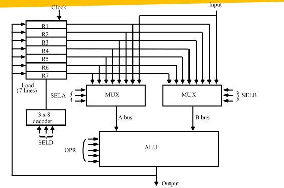
GENERAL REGISTER ORGANIZATION
Continued …
General Register Organization
MUX
SELA
{
MUX}
SELBALU OPR R1 R2 R3 R4 R5 R6 R7 Input
3 x 8 decoder
SELD Load
(7 lines)
Output
A bus B bus
[image:18.720.107.660.113.480.2]Clock
19 19
OPERATION OF CONTROL UNIT
To perform the following operation, the control unit
20 20
Register Stack Organization
(Last-in First-out)
21 21
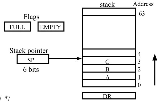
REGISTER STACK ORGANIZATION Continued …
Register Stack
Push, Pop operations
/* Initially, SP = 0, EMPTY = 1, FULL = 0 */
PUSH POP
Stack Organization
SP
←SP + 1
DR
←M[SP]
M[SP]
←DR
SP
←SP − 1
If (SP = 0) then (FULL
←1) If (SP = 0) then (EMPTY
←1)
EMPTY
←0
FULL
←0
Stack
- Very useful feature for nested subroutines, nested interrupt services
- Also efficient for arithmetic expression evaluation
- Storage which can be accessed in LIFO
- Pointer: SP
- Only PUSH and POP operations are applicable
[image:21.720.352.654.184.379.2]A B C 0 1 2 3 4 63 Address FULL EMPTY SP DR
Flags
Stack pointer
stack
6 bits
22 22
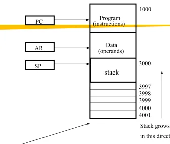
MEMORY STACK ORGANIZATION Continued …
Stack Organization
- A portion of memory is used as a stack with a
processor register as a stack pointer
- PUSH: SP ← SP - 1
M[SP] ← DR
- POP: DR ← M[SP]
SP ← SP + 1
Memory with Program, Data, and Stack Segments
4001 4000 3999 3998 3997 3000 Data (operands) Program (instructions) 1000 PC AR SP
stack
Stack growsin this direction
- Most computers do not provide hardware to check stack overflow (full stack) or underflow (empty stack) must be done in software
PC points at address of next instruction
[image:22.720.336.672.64.348.2]AR points to an array of data SP points at the top of the stack
23 23
28 28
Conversion to RPN
•
Infix notation
to RPN takes into consideration
the following
operational hierarchy
for infix
notation which dictates the following:
• First perform all arithmetic inside parentheses
• Then inside outer parentheses
• Multiplication and division
30 30
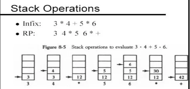
REVERSE POLISH NOTATION (RPN)
A + B Infix notation
+ A B Prefix or Polish notation
A B + Postfix or reverse Polish notation
- The reverse Polish notation is very suitable for stack manipulation
•
Evaluation of Arithmetic Expressions
Any arithmetic expression can be expressed in parenthesis-free
Polish notation, including reverse Polish notation
(3 * 4) + (5 * 6) ⇒ 3 4 * 5 6 * +
Stack Organization
•
Arithmetic Expressions
: A + B
3 3 12 12 12 12 42
4 5 5
6
30
3 4 * 5 6 * +
31 31
33 33
PROCESSOR ORGANIZATION
•
In general, most processors are organized in one of 3 ways
–
Single register
(Accumulator) organization
•
Basic Computer is a good example
•
Accumulator is the only general purpose register
–
General register
organization
•
Used by most modern computer processors
•
Any of the registers can be used as the source or
destination for computer operations
–
Stack
organization
•
All operations are done using the hardware stack
•
For example, an OR instruction will pop the two top elements
37 37
39 39
INSTRUCTION FORMAT
OP-code field - specifies the operation to be performed
Address field - designates memory address(es) or a processor register(s) Mode field - determines how the address field is to be interpreted (to
get effective address or the operand)
• The number of address fields in the instruction format
depends on the internal organization of CPU
• The three most common CPU organizations:
Instruction Format
Single accumulator organization
:
ADDX
/* AC
←
AC + M[X] */
General register organization
:
ADDR1, R2, R3 /* R1
←
R2 + R3 */
ADD R1, R2
/* R1
←
R1 + R2 */
MOV
R1, R2
/* R1
←
R2 */
ADD R1, X
/* R1
←
R1 + M[X] */
Stack organization
:
PUSH
X
/* TOS
←
M[X] */
ADD
40 40
•
Three-Address Instructions
Program to evaluate X = (A + B) * (C + D) :
ADD R1, A, B /* R1 ← M[A] + M[B] */ ADD R2, C, D /* R2 ← M[C] + M[D] */
MUL X, R1, R2 /* M[X] ← R1 * R2 */
- Results in short programs
- Instruction becomes long (many bits)
•
Two-Address Instructions
Program to evaluate X = (A + B) * (C + D) :
MOV R1, A /* R1 ← M[A] */
ADD R1, B /* R1 ← R1 + M[A] */
MOV R2, C /* R2 ← M[C] */
ADD R2, D /* R2 ← R2 + M[D] */
MUL R1, R2 /* R1 ← R1 * R2 */
MOV X, R1 /* M[X] ← R1 */
Instruction Format
41 41
ONE, AND ZERO-ADDRESS INSTRUCTIONS
•
One-Address Instructions
- Use an implied AC register for all data manipulation
- Program to evaluate X = (A + B) * (C + D) :
Instruction Format
LOAD A /* AC ← M[A] */
ADD B /* AC ← AC + M[B] */
STORE T /* M[T] ← AC */
LOAD C /* AC ← M[C] */
ADD D /* AC ← AC + M[D] */
MUL T /* AC ← AC * M[T] */
STORE X /* M[X] ← AC */
•
Zero-Address Instructions
- Can be found in a stack-organized computer
- Program to evaluate X = (A + B) * (C + D) :
PUSH A /* TOS ← A */ PUSH B /* TOS ← B */
ADD /* TOS ← (A + B) */ PUSH C /* TOS ← C */
PUSH D /* TOS ← D */
ADD /* TOS ← (C + D) */
42 42
ADDRESSING MODES
Addressing Modes
•
Addressing Modes
* Specifies a rule for interpreting or modifying the
address field of the instruction (before the
operand is actually referenced)
* Variety of addressing modes
- to give programming flexibility to the user
- to use the bits in the address field of the
46 46
TYPES OF ADDRESSING MODES:EXAMPLES
•
Implied Mode
Address of the operands are specified implicitly
in the definition of the instruction
- No need to specify address in the instruction
- EA = AC, or EA = Stack[SP]
- Examples from Basic Computer
CLA, CME, INP
•
Immediate Mode
Instead of specifying the address of the operand,
operand itself is specified
- No need to specify address in the instruction
- However, operand itself needs to be specified
- Sometimes, require more bits than the address
- Fast to acquire an operand
47 47
TYPES OF ADDRESSING MODES
•
Register Mode
Address specified in the instruction is the register address
- Designated operand need to be in a register
- Shorter address than the memory address
- Saving address field in the instruction
- Faster to acquire an operand than the memory addressing
- EA = IR(R) (IR(R): Register field of IR)
•
Register Indirect Mode
Instruction specifies a register which contains
the memory address of the operand
- Saving instruction bits since register address
is shorter than the memory address
- Slower to acquire an operand than both the
register addressing or memory addressing
- EA = [IR(R)] ([x]: Content of x)
•
Autoincrement
or
Autodecrement Mode
- When the address in the register is used to access memory, the value in the register is incremented or decremented by 1 automatically
48 48
TYPES OF ADDRESSING MODES
Addressing Modes
•
Direct Address Mode
Instruction specifies the memory address which can be used
directly to access the memory
- Faster than the other memory addressing modes
- Too many bits are needed to specify the address
for a large physical memory space
- EA = IR(addr) (IR(addr): address field of IR)
•
Indirect Addressing Mode
The address field of an instruction specifies the address of a
memory location that contains the address of the operand
- When the abbreviated address is used large physical memory
can be addressed with a relatively small number of bits
- Slow to acquire an operand because of an additional memory
access
49 49
TYPES OF ADDRESSING MODES
Addressing Modes
•
Relative Addressing Modes
The Address fields of an instruction specifies the part of the address (abbreviated address) which can be used along with a designated register to calculate the address of the operand
- Address field of the instruction is short
- Large physical memory can be accessed with a small number of address bits - EA = f(IR(address), R), R is sometimes implied
3 different Relative Addressing Modes depending on R;
*
PC Relative Addressing
Mode
(R = PC) - EA = PC + IR(address)
* Indexed Addressing Mode
(R = IX, where IX: Index Register) - EA = IX + IR(address)50 50
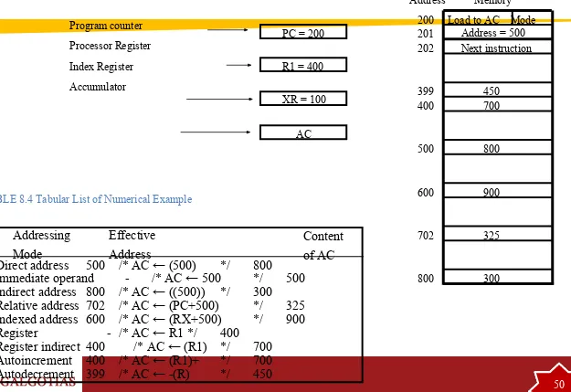
ADDRESSING MODES - EXAMPLES
-Addressing
Mode
Effective
Address
Content
of AC
Addressing Modes
Direct address
500
/* AC ← (500)
*/ 800
Immediate operand
-
/* AC ← 500
*/ 500
Indirect address 800
/* AC ← ((500))
*/ 300
Relative address 702
/* AC ← (PC+500)
*/ 325
Indexed address 600
/* AC ← (RX+500)
*/ 900
Register
- /* AC ← R1 */ 400
Register indirect 400 /* AC ← (R1) */ 700
Autoincrement
400 /* AC ← (R1)+
*/ 700
Autodecrement
399 /* AC ← -(R)
*/ 450
Load to AC Mode Address = 500 Next instruction 200 201 202 399 400 450 700 500 800 600 900 702 325 800 300 Memory Address
PC = 200
R1 = 400
XR = 100
[image:50.720.57.682.92.521.2]AC
TABLE 8.4 Tabular List of Numerical Example
Program counter
Processor Register
Index Register