ScholarWorks@UNO
ScholarWorks@UNO
University of New Orleans Theses and
Dissertations Dissertations and Theses
8-7-2003
VNC Service on Bluetooth Wireless Network
VNC Service on Bluetooth Wireless Network
Rui Xia
University of New Orleans
Follow this and additional works at: https://scholarworks.uno.edu/td
Recommended Citation Recommended Citation
Xia, Rui, "VNC Service on Bluetooth Wireless Network" (2003). University of New Orleans Theses and Dissertations. 37.
https://scholarworks.uno.edu/td/37
This Thesis is protected by copyright and/or related rights. It has been brought to you by ScholarWorks@UNO with permission from the rights-holder(s). You are free to use this Thesis in any way that is permitted by the copyright and related rights legislation that applies to your use. For other uses you need to obtain permission from the rights-holder(s) directly, unless additional rights are indicated by a Creative Commons license in the record and/or on the work itself.
VNC SERVICE ON BLUETOOTH
WIRELESS NETWORK
A Thesis
Submitted to the Graduate Faculty of the University of New Orleans
in partial fulfillment of the requirements for the degree of
Master of Science in
The Department of Computer Science
by
Rui Xia
B.S. University of Science and Technology of China
ii
Acknowledgments
I would like to express my gratitude to those who have helped me and supported me through the years of my graduate study and research project. I am especially grateful to my advisor, Dr. Golden G. Richard III, for his continuous guidance, inspiration and enthusiasm. Special thanks to members of my committee: Dr. Shenru Tu and Dr. Ming-Hsing Chiu for their comments and advice. And I’d like to thank Dr. Eduardo Kortright, who gave me the precious opportunity to work as a graduate assistant.
I am also thankful to graduate student Shi Wei, Gao Yun for their assistance and discussions.
iii
Table of Contents
Acknowledgments...ii
Table of Contents...iii
List of Tables...iv
List of Figures ...v
Abstract ...vi
Introduction...1
Chapter 1 Bluetooth Technology...3
Chapter 2 Security Issues in Bluetooth ... 21
Chapter 3 Introduction to VNC Protocol... 28
Chapter 4 VNC Services on Bluetooth... 34
Chapter 5 Performance Test and Result... 49
Chapter 6 Conclusion and Future Work... 55
Reference... 58
iv
List of Tables
Table 1 Comparison between Bluetooth and IEEE 802.11 Direct Sequence Spread Spectrum 6
Table 2 Different types of access code... 11
Table 3 Different initialization key depending on type of PINs Bluetooth devices have ... 23
Table 4 Comparison between RFB, X window and Netmeeting ... 30
Table 5 Response time (whole frame, no background)... 51
Table 6 Response time (single window)... 51
v
List of Figures
Figure 1 Bluetooth hop frequency selection ...7
Figure 2 Bluetooth protocol stack [4]... 15
Figure 3 Steps in a pointer event handling in VNC (windows version)... 32
Figure 4 SDP Discovery Procedure... 35
Figure 5 Code fragment to create new service record (server side)... 37
Figure 6 Code fragment to create new service record attribute (server side)... 38
Figure 7 Code fragment for service discovery (client side) ... 39
Figure 8 Code fragment to add a customer attribute (server side)... 40
Figure 9 Code fragment to request an attribute (client side)... 40
Figure 10 Code fragment for inquiry event handler (from Digianswer software suite)... 41
Figure 11 Code fragment to filter out pointer messages... 43
Figure 12 Code fragment to limite update to only selected window... 44
Figure 13 Code fragment to add a hook to prevent a window from being close ... 45
Figure 14 Modified VNC server property dialog ... 46
Figure 15 VNC on Bluetooth starter program ... 47
Figure 16 VNC on Bluetooth client program... 48
Figure 17 Code fragment to measure response time... 50
Figure 18 Initial loading times in different conditions ... 52
vi
Abstract
Introduction
A VNC service provides a remote GUI console for clients from multiple operating systems. For example, a user working on a Windows workstation can access a X window Solaris; a PDA running Windows CE can access a Macintosh. Serving as a multi-platform interface, VNC gives computer users a great freedom of interoperation between individual machines.
A VNC client transfers local mouse and keyboard inputs into RFB (Remote Frame Buffer) messages and passes those messages to VNC server. The VNC server transfers the RFB messages back into messages readable by local operating system and lets the local operating system process them. The updates on server desktop screen are sent to each client in the form of a series of pixel rectangles.
Developed as a “thin-client” protocol, VNC does not require client machines be capable of intensive computing. This coincides with the profiles of most Bluetooth units, of which a great majority are of hand-held size.
Bluetooth is a communication technology aiming at small-size, low power-consumption, pocket size appliances. Also, it has features like service discovery, built-in security, etc.
situation); you can, with a PDA, access servers in a rack configuration that have no attached monitor or input device but a Bluetooth card.
Modification to original VNC program is made. The VNC server can filter the user input messages so that only those inside a particular window will be processed and only the screen updates inside the window will be sent back to clients. By doing this, we can limit the access of clients to only the resources of a particular window. In this way, all programs targeting at local users can be accessed by remote users as well, an easy alternative for conventional client-server programming.
Bluetooth can provide free encryption for VNC. Furthermore, the function of the particular window can be advertised with Bluetooth Service Discovery.
Chapter 1 Bluetooth Technology
Overview
To be concise, Bluetooth is a wireless communication technology developed by Bluetooth SIG (Special Interest Group) in 1998 to replace the cable(s) connecting portable and/or fixed electronic devices. Key features are robustness, low complexity, low power, and low cost [4]. Comparing with already existing IEEE 802.11 family wireless technologies, Bluetooth has some distinctive features like built-in service discovery, encryption, power mode control, etc.
Bluetooth aims mainly at market in pocket-size device for which battery is almost the only choice for power supply. The Bluetooth specification defines 3 power classes to suit for equipments with different antenna power output. By switching power mode from active mode to sniff or park mode, Bluetooth devices can greatly extend the working life without recharging battery.
As IEEE 802.11 does, Bluetooth also suffers from multi-path propagation and signal interference. Due to the shorter radio range, Bluetooth suffers less from multi-path propagation than IEEE 802.11 radio. Using frequency-hopping, Bluetooth can eventually recover from narrow-band interference that may only affect one hopping frequencies used by Bluetooth.
In encryption mode, the data packets transmitted between two Bluetooth devices are protected with an ever changing cipher stream. Combining with frequency-hopping, “sniffing” by malicious receiver is made more difficult.
adaptation protocol; and then higher protocol and applications. Not like JINI for Java or UPnP of XML, the service discovery protocol(SDP) of Bluetooth sit right above Link Manager Protocol (LMP) instead of application level, thus is more efficient and cause less system overhead.
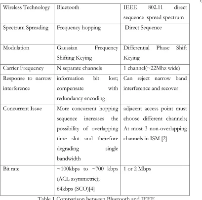
Because of the similarity with IEEE 802.11 radio technology, a comparison can be made between Bluetooth and IEEE 802.11 direct sequence spreading spectrum. IEEE 802.11 standard has more than one physical layers: Frequency Hopping Spread Spectrum (FHSS), Direct Sequence Spread Spectrum (DSSS), High Rate Direct Sequence Spread Spectrum (HR-DSSS), Orthogonal Frequency Division Multiplexing (OFDM), Infrared [2]. Because only FHSS and DSSS work in the same 2.4GHz band as Bluetooth and FHSS is only slightly different from Bluetooth, the comparison is made mainly between Bluetooth and IEEE 802.11 with DSSS physical layer.
Radio Technology
Bluetooth radio is working in ISM (Industrial Scientific Medicine) band which has radio frequency range 2.4000-2.4835 GHz (in USA and most other countries, some countries like France has small variation). This range of frequency is divided into channels f = 2.402 + k MHz (k = 0 … 78) for frequency hopping. At the beginning, 32 channels out of the 79 channels are chosen; then signals are transmitted over one of the 32 channels for a period of time and the frequency will hop to another one of the 32 channels for the next period of time and so on in a random permutation order. Next, another set of 32 channels are selected and so on. In contrast, IEEE 802.11 uses a continuous frequency band (about 22MHz wide) inside the ISM band.
Radio transmitters used in Bluetooth are categorized into 3 power level classes and communication between LMPs can be made to adjust the antenna transmitting power level to set up an optimal RF connection.
is detected by receiver and a phase change in one bit transmit period may represent bit “1” and no phase change may represent bit “0”.
To fight against interference, both Bluetooth and IEEE 802.11 DSSS use spectrum spreading. Because radio interference is usually in a narrow frequency band, spreading frequency spectrum will generally recover from narrow frequency interference.
Bluetooth utilizes frequency hopping Code-Division Multiple Access (CDMA). Transmitter and receiver of Bluetooth must set a common frequency hopping sequence during some kind of “hand-shaking” procedure and before information bits can flows. Time is divided into time slots; during each time slot, both sender and receiver use same frequency and hop to another frequency in the next time slot, and so on. There can be multiple transmitting in the air in the same time—each applies different hopping sequence and those sequences can be chosen to be random in order to minimize overlapping. Intuitively, increasing number of concurrent transmitting will result in more occasional overlapping and decrease bandwidth for every individual transmitting; however, in the meantime, the overall bandwidth could still increases.
Direct Sequence CDMA is different from frequency hopping CDMA. On sender side, information bit sequence is XORed with a high-speed Pseudo Random Sequence (chip sequence) and transmitted on a carrier frequency; on receiver side, a filter constructed from the same chip sequence checks the correlation of the received signal and information bit is obtained. Multiple transmitting is made possible with the use of different pseudo random sequences. IEEE 802.11 Direct Sequence Spread Spectrum (DSSS) is similar to ordinary Direct Sequence CDMA, the only difference being that all IEEE 802.11 DSSS use the same pseudo random sequence [2].
The frequency hopping CDMA used in Bluetooth is more cost-effective and has less complex circuit than direct sequence CDMA used in IEEE 802.11; but the latter can achieve higher bandwidth [1].
Wireless Technology Bluetooth IEEE 802.11 direct sequence spread spectrum Spectrum Spreading Frequency hopping Direct Sequence
Modulation Gaussian Frequency Shifting Keying
Differential Phase Shift Keying
Carrier Frequency N separate channels 1 channel(~22Mhz wide) Response to narrow
interference
information bit lost; compensate with redundancy encoding
Can reject narrow band interference and recover
Concurrent Issue More concurrent hopping sequence increases the possibility of overlapping time slot and therefore
degrading single bandwidth
adjacent access point must choose different channels; At most 3 non-overlapping channels in ISM [2]
Bit rate ~100kbps to ~700 kbps (ACL asymmetric);
64kbps (SCO)[4]
1 or 2 Mbps
Table 1 Comparison between Bluetooth and IEEE 802.11 Direct Sequence Spread Spectrum
Bluetooth Baseband Protocol
Baseband protocol in Bluetooth covers the aspect of how Bluetooth devices organize data packets and send them via radio and this is the lowest in the protocol layers of Bluetooth and implemented by hardware. The counterpart in IEEE 802.11 is the PHY layer.
Clock and Frequency Hopping
timing but also plays a great role in radio transmitting and receiving. Actually there is also an offset register in Bluetooth that compensates the difference between the two native clocks in order that two Bluetooth devices can synchronize. When two Bluetooth devices come in contact, a master-slave relation is established and the slave Bluetooth device will set its offset register to the difference between the two native clocks so the sum of the slave’s native clock and the offset equals to the master’s native clock.
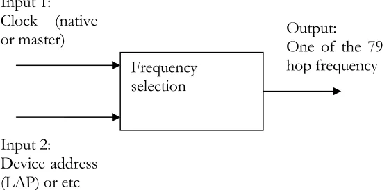
As mentioned above, time slots are defined and for each time slot a particular frequency (called hop frequency) selected from a frequency hopping sequence is used for either sender or receiver on a Bluetooth device. This is the so-called “frequency hopping” technology. To fight against interference, hopping sequence must be random in a relative long time period. For this reason, additional information (usually a Bluetooth device address and/or some device class code) as well as clock value is fed into “frequency selection box” to achieve high degree random.
Figure 1 Bluetooth hop frequency selection
Bluetooth device address
Here we come across the term “Bluetooth device address”. This is nothing different from the MAC address of an Ethernet card. This unique 48-bit address contains 3 fields: a 24-bit lower address part (LAP), an 8-24-bit upper address part (UAP) and a 16-24-bit non-significant part (NAP). One function of the Bluetooth address is to uniquely identify a Bluetooth device; the other function is to help to generate hopping sequence.
Frequency selection Input 1:
Clock (native or master)
Input 2: Device address (LAP) or etc
Master and Slave
When one Bluetooth device wants to set up a connection with another Bluetooth device, it initializes the connection and thereafter assumes a “master” role; on the other hand, the other Bluetooth device assumes a “slave” role. This situation will remain unchanged until one of them sends to the other a request for switching roles and switching is then successfully performed.
This master-slave relation is not only limited to one but also can be one-to-multiple. One of the master and one or more slaves construct a “piconet”. In a piconet, the slave(s) synchronize with the master by setting the offset register. When in connection mode, all members in the piconet synchronize to the same clock (master’s native clock) and acquire master’s device address and use these two parameters to select common hopping sequence. In such a way, the master determines the characteristics of the piconet.
For comparison, in IEEE 802.11, stations are all equal. Stations share the transmitting medium with carrier-sense multiple access with collision avoidance (CSMA/CA). There can be a point coordinator at a central access point which can assume a master role and coordinates other stations for time-bounded tasks [2].
In a Bluetooth piconet, time slots are numbered according to master clock. The master-to-slave and slave-to-master transmitting share the medium (air) in a time-duplex way. The master-to-slave transmitting always starts at odd number slots; while slave-to-master transmitting always starts at even number slots.
SCO Links and ACL Links
There are two kinds of links between a master and a slave: synchronous connection-oriented (SCO) link and asynchronous connection-less (ACL) link.
integrity checking or retransmission for a SCO link. Usually SCO links are used to transmit voice stream in Bluetooth.
The other type of link is ACL link. The master makes use of the slots not reserved for SCO links by sending a packet to a slave and expects a return packet from the address slave. If a slave can not recognize the address in the incoming packet, it must not respond. Multicast is possible by setting the address to a multicast address in the master-to-slave packet. In contrast to SCO links, ACL links have integrity-checking and retransmission support. In this way, the master polls its slaves and a slave only responds passively.
Connection Setup
A Bluetooth device can be in one of the following states: standby, connection, page, page scan, master response, slave response, inquiry, inquiry scan, inquiry response. Communication is possible only when both Bluetooth devices are in connection state. To establish a communication channel, Bluetooth devices must follow page procedure and make transitions between a series of states.
1. Initially, two Bluetooth devices are both in standby state. One Bluetooth device could have knowledge of the address of another Bluetooth device in the radio proximity. Usually the knowledge of Bluetooth device address is obtained through inquiry (One device in inquiry state sends out a inquiry packet and waits for FHS packets sent back by other devices in inquiry response state and the address information is contained in FHS packets).
2. Then one Bluetooth device initiates page procedure by entering page state and will become master. The target’s device access code (it may be obtained from a inquiry procedure) is transmitted repeatedly over a sequence of frequency. This sequence is derived from the target’s Bluetooth address and target’s estimated clock.
firmware layer that translates uniform HCI commands and drives the Bluetooth hardware). Similarly, this Bluetooth device listens over a sequence of frequency derived from Bluetooth address and clock and maintains a correlator window against its own device access code. When a paging with correct access code is noticed by this Bluetooth device, it enters into slave response state and sends back a response containing its access code.
4. The master Bluetooth device enters into master response state upon receiving the response message from the slave. The master will transmit a FHS packet containing vital information about channel set-up (such as master’s address, master’s clock, etc.) and waits for the second response.
5. The slave Bluetooth device receives the FHS packet and sends back a second response to acknowledge the receipt of FHS. Using the information from the FHS packet, the slave can obtains the new channel access code and channel frequency hopping sequence that can be used thereafter.
6. The master Bluetooth device receives the second response from the slave. Now both master and slave are in connection state.
Packets
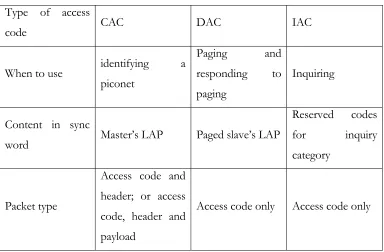
The most basic transmission unit in Bluetooth is a packet. A packet can have up to 3 parts: access code only; access code and header; access code, header and payload.
possible that one in piconet P listens on a packet from another piconet, if the packet has a channel access code other than P, then the packet can be ignored.
Type of access
code CAC DAC IAC
When to use identifying a piconet
Paging and responding to paging
Inquiring
Content in sync
word Master’s LAP Paged slave’s LAP
Reserved codes for inquiry category
Packet type
Access code and header; or access code, header and payload
Access code only Access code only
Table 2 Different types of access code
Consisting of 6 fields, the header contains link control (LC) information.
• AM_ADDR: 3- bit active member address
In a piconet, each active member is assigned a 3-bit address to replace its cumbersome 48-bit Bluetooth device address. The number of active members is limited to 8; however an active member can enter into inactive mode (e.g. hold, sniff, sleep) and release it active member address so the master can assign it to another member which just joins in this piconet or comes back from an inactive mode. In this way, the number of members in a piconet can be greater than 8. The slave whose member address is included in the previous master-to-slave packet notice this and responds in the next slave-to-master time slot; other slaves will just do nothing and wait for their calls.
Combined with information of if the link is SCO link or ACL link, this type code indicates the type and function of the packet it belongs to. Different types of packets differ in what is the content of payload, how many slots the packet covers, how many bits in the packet, how ACK is handled, how error correction is carried out, etc. Details can be obtained from Bluetooth specification [4].
• FLOW: 1-bit flow control
This flow control will be toggled according to if the buffer on receiver side is full or not. In response, the sender will stop the flow until the flow signal is reset.
• ARQN: 1-bit acknowledge indication
This ACK bit provides a basic method for acknowledgment. This bit can be piggy-back in the return packet.
• SEQN: 1-bit sequence number
In case that receiver successfully receives a packet, but the acknowledgement does not get through to the sender, the sender may choose to re-transmit the same packet with the 1-bit SEQN set; the receiver can notice the SEQN and drop the second packet.
• HEC: 8-bit header error check
The receiver uses this to check the integrity of the header.
The payload consists of up to 3 fields: payload header, payload body and payload CRC. Two types of payload are present. The voice payload has a payload body of fixed length, either 240 bits or 80 bits; and there is no payload header or CRC for voice payload. The data payload has a header and possibly a CRC besides a payload body.
code is used to determine the type of the logical channel the packet belongs to. The logical channel flow control is handled on link manager level and the flow control bit in packet header is handled by link controller.
Logical Channels
In Bluetooth, 5 logical channels are defined:
• LC (Link Control) channel
Mapped onto packet headers, this channel carries information of payload type, flow control and ARQ (auto-retransmit quest).
• LM(Link Manager) channel
Mapped onto packet payload with certain payload header (logical channel code set as 11), LM channel carries information between link managers on master and slave. The information is used for link set-up and link control.
• UA (User Asynchronous) Channel
Mapped onto packet payload with certain payload header (logical channel code set as 01 or 10), UA channel transfer asynchronous user data.
• UI (User Isochronous) Channel
Similar to UA channel, UI channel transfers isochronous user data by starting packet timely at higher protocol level
• US (User Synchronous) Channel
Note that LM channel has priority over the other three user data channels, meaning that, if necessary, a LM packet could preempt a time slot originally for user data channel and the receiving slave must be able to notice the change.
Error Control
Unlike the DSSS in IEEE 802.11 that use high processing gain to withstand narrow band interference and recover [2], the frequency hopping in Bluetooth use FEC (Forward Error Correction) coding to detect error and recover [3].
Two FEC coding are used: 1/3 FEC coding (simply repeating information bit three times) is used on packet header and less powerful 2/3 FEC coding (a [15, 10] Hamming code which has 10 information bits out of total 15 bits and detects all 1 and 2 bits errors and corrects all 1 bit errors) is used on data field in some types of packet. FEC coding can reduce the number of retransmission by detecting and recovering from certain errors.
Besides FEC coding, CRC is used to detect transmission error. Part of the address is used as initial values of registers in LFSR (Line Feedback Shift Register) on sender side and the CRC code generated from information bits is attached with the information bits themselves; On receiver side, the receiver use the same partial address to generate CRC code from information bits in the received packet, then comparison is made against the CRC code attached in the packet.
Bluetooth use ARQ (Automatic Repeat Request) for some types of packets, where the sender waits for a ACK as a result of successful packet transfer or a time-out.
Link Manager Protocol Overview
Link Manager Protocol handles link setup and control. As mentioned above, link management packets have their logical channel codes set as 11 in packet payload header.
To set up a link or modify one of the link characteristics (e.g. change the link key), Bluetooth devices exchange a sequence of LM PDUs. Such a sequence is called a transaction.
At the first byte of payload body of each LMP, there is an opcode and a transaction id. The opcode indicates the function of each LM PDU; the transaction id is used to identify whether the master or the slave initiates a transaction sequence. The following bytes of the payload body have information about the LM PDU. Details of every opcode can be obtained from Bluetooth specification.
Figure 2 Bluetooth protocol stack [4]
Link Setup
The procedure of link setup is as following:
1. Through paging procedure, piconet channel is set up and both Bluetooth devices are in connection state. By receiving FHS packet from master, the slave has knowledge of the clock value and address of the master.
2. By exchanging clock offset PDUs, the master has record of the clock offset of the slave and it can accelerate next paging to the slave; by exchanging LM version PDUs, one Bluetooth device can know the version and manufacture company id of the other; by exchanging supported features PDUs, one Bluetooth device can know what optional features the other supports; by
Baseband
ACL link SCO link LMP L2CAP
Audio RFCOMM
exchanging name PDUs, one Bluetooth devices can know the user-friendly name of the other
3. The master sends a host connection request PDU.
4. The slave sends a PDU indicating whether the connection request is accepted.
5. Then both Bluetooth devices begin the pairing process. At least one of the Bluetooth devices must have a variable PIN in order to generate a secure link key. The details will be covered in the next chapter about Bluetooth security.
6. Authentication can be carried out by sending an auth PDU with a random number to the peer and an auth result is expected from the peer. The valid auth result should be a function of the random number and the link key shared by the pair.
7. Optional encryption negotiation can be carried out by generating a secret encryption key from a random number and the current link key.
8. The master sends a setup complete PDU and the slave responds by sending a setup complete PDU. Now an ACL link is set up between the master and the slave.
9. SCO links can be set up by exchanging SCO link setup PDUs. Note that only one ACL link can exist between a master and a slave while SCO link has the capacity of 3.
Hold, Sniff and Park Modes
While in connection state, a Bluetooth device can be placed in hold, sniff or park mode. This is done by exchanging hold mode PDUs, sniff mode PDUs or park mode PDUs.
A device in hold mode can perform paging, inquiry and participate in another piconet during its hold time.
Sniff mode PDU contains parameters for sniff interval and sniff duration (every interval time slot, the slave wakes up and sniffs for several slots for packets addressed to it and remains in a low-power state the rest of time).
Park mode PDU contains a park address and an access request address. In park mode, the slave relinquishes its active member address and obtains a park address and an access request address. The former address is used for the master to wake up the slave from its park mode and the latter is used for the slave to request to be active again. A Bluetooth device in park mode consumes the least power.
The three modes above provide time multiplexing ability. While not an active member in a piconet, a slave or master can be active in another piconet. Thus a scatternet is formed. A scatternet is a group of piconets in which connections consists between different piconets and provides more flexibility than multiple individual piconet.[4]
Frames in IEEE 802.11
The Medium Access Control (MAC) layer in IEEE 802.11 handles MAC PDU (MPDU) or frame. A frame has a MAC header, a frame body, and a frame checksum.
Some important fields in the MAC header are listed as following:
• 2-octet frame control containing control information (most important is the type of the frame). Control type frames controls the data flow; management type frames carry out connection setup (association/disassociation, authentication, etc.); data frames contain user data.
• A 2-octet sequence control containing sequence information of segmentation of logical link control data unit (MSDU), which is a data unit from higher layer, and sequence number of individual logical link control data unit.
Each MPDU is passed to physical layer to form a PHY PDU (PPDU) to send over air. Basically, the PHY layer puts synchronization bits and length before MPDU.
A frame is comparable to a packet in Bluetooth except for its variable length. Ideally, a frame can be of any length and one frame can be used for one MSDU. However, fragmentation of MSDU increases the probability of successful transmission of a frame at cost of a little overhead. On the other hand, in Bluetooth, fragmentation results from the innate frequency-hopping mechanism.
In Bluetooth, devices in a piconet have dynamically allocated active member addresses and the scope is only in the piconet. In IEEE 802.11, all addresses are global and used for both intra BSS and inter BSS communication.
Logical Link Control and Adaptation Protocol (L2CAP)
The L2CAP protocol layer is placed between the lower Baseband and other higher protocols (SDP, RFCOMM, etc.). The functions of L2CAP include:
• Multiplexing the single ACL link between the master and the slave for multiple logical links needed for all higher protocols;
• Segmenting larger and flexible length transmission units for higher protocols to the smaller, fixed length Baseband packets and reassembling the other way;
• Grouping devices for multicast purpose;
• Conveying QoS information.
specification; the others (0x0040 to 0xffff) are dynamically allocated for user. Among the reserved CIDs are two special ones: 0x0001 for signaling and 0x0002 for connectionless reception. Note that CIDs have scope only in the Bluetooth device.
Defined in L2CAP are various types of channels:
• Bidirectional connection-oriented channel between local endpoint (0x0040 to 0xffff) and remote endpoint (0x0040 to 0xffff);
• Bidirectional signaling channel between local endpoint (0x0001) and remote endpoint (0x0001);
• Unidirectional connectionless channel between local endpoint (0x0040 to 0xffff) and remote endpoint (0x0002). The data flow is from local endpoint to remote endpoint only.
Signaling channel is used for L2CAP channel connection and configuration. Connection-oriented channel is used to transfer user data. Connectionless channel is use to multicast data for higher protocols.
The L2CAP packet has the following structure:
• For a connection-oriented channel, the packet consists of a 16-bit payload length in bytes, followed by a 16-bit destination CID (0x0040 to 0xffff), and then the payload.
• For a signaling channel, the packet consists of a 16-bit payload length, followed by a 16-bit destination CID (0x0001) and then one or more command units. Each command unit consists of a bit command code, a 8-bit identifier (to distinguish outstanding command transactions) and a 16-8-bit length.
and the payload. The PSM is to determine which higher protocol or service this packet should be forwarded to.
The L2CAP provides the following service primitives to higher protocols (mostly channel identifier and Bluetooth address are input parameters) such as connect, disconnect, read, write, etc.
Logical Link Control in IEEE 802.11
The Logical Link Control (LLC) layer is the highest layer defined in IEEE 802.11. The LLC PDU consists of following 4 fields:
• 8-bit Destination Service Access Point;
• 8-bit Source Service Access Point;
• 8-bit Control;
• Variable length data.
LLC provides 3 types of connections: unacknowledged connectionless, acknowledged connectionless and connection-oriented. The difference is the trade-off between time-bound ability and reliability.
Higher Protocols in Bluetooth
Chapter 2 Security Issues in Bluetooth
Overview
Security is always a vital issue for network system. For the wired network (like a telephone network), great effort is taken to guard the physical lines from unauthorized access. In some case, the nature of the transmitting medium itself is a great factor in security (i.e. an optical fiber is very hard to “tap” than an ordinary telephone line). However, due to the wide spreading of radio wave, it is hard to prevent wireless transmission from being eavesdropped. For this reason, wireless network needs more attention when security is concerned.
In computer network security there are three basic principles: confidentiality, integrity and availability [3].
• Confidentiality means that information is only received by intended receiver. Obviously disclosure of sensitive information to unauthorized party will certainly cause harm.
• Integrity refers to that information must be delivered to the receiver unaltered. Sometimes integrity deserves more concern than confidentiality when financial communities conduct the business.
• Availability means that service is always available when a user wants it. Denial of Service (DoS) attack is a famous example of malicious attempts to compromise the availability of the network.
yourself. But with a secure channel all above (integrity, confidentiality and authentication) can be done in a more efficient and much easier fashion. The above is an example for integrating security into network protocols. Bluetooth has security measure on nearly every protocol layer.
First of all, Bluetooth uses frequency hopping that makes eavesdropping much difficult. The radio frequency used for a Bluetooth link changes 1600 times per second. The hop frequency chosen for a time slot is a function of 28-bit part of the master Bluetooth device address and the 27-bit master clock. Even though the master Bluetooth device address is fixed and is publicly known, one can only get the master clock by being paged by the master Bluetooth device or by exchanging clock offset LM PDUs during link setup.
Keys are used in Bluetooth for security reason. Basically, a key is a bits string of fixed or variable length shared only between two Bluetooth devices. Function-wise, 3 types of keys exist in Bluetooth: initialization key, link key and encryption key. Initializations keys are used in securing the negotiation of link keys; link keys are used for authentication and to generate encryption keys; encryption keys are used to cipher and decipher communication. Note that generation of keys and ciphering/deciphering in Bluetooth are performed by hardware at no cost of computing power of host CPU.
Though a promising technology, Bluetooth still has a list of vulnerabilities [10] and is under development. A detailed discussion on security issue can be found in [9], in which two general recommendations for Bluetooth security are given:
• Use combinational key instead of unit key because a trusted unit B which has been given A’s unit key can easily impersonate unit A;
Initializations Keys
For initialization key (Kinit) generation, algorithm E22 is used. In algorithm E22, the
inputs include a Bluetooth address, a 128-bit random number, a L-octet PIN and the length L and the output is a 128-bit key.
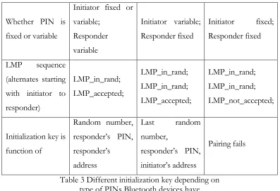
On the two Bluetooth devices, PINs are either fixed or variable, but at least one of the two Bluetooth devices needs to have a variable PIN for successful paring. In another word, two Bluetooth devices both with fixed PINs can not pair.
Whether PIN is fixed or variable
Initiator fixed or variable; Responder variable Initiator variable; Responder fixed Initiator fixed; Responder fixed LMP sequence (alternates starting with initiator to responder) LMP_in_rand; LMP_accepted; LMP_in_rand; LMP_in_rand; LMP_accepted; LMP_in_rand; LMP_in_rand; LMP_not_accepted;
Initialization key is function of Random number, responder’s PIN, responder’s address Last random number, responder’s PIN, initiator’s address Pairing fails
Table 3 Different initialization key depending on type of PINs Bluetooth devices have
On one hand, the default PIN is 0, which is a serious potential security loophole. On the other hand, the most secure case would be that both devices have variable PINs and those two PINs are manually input through man-machine interface.
Once initialization keys are calculated on both Bluetooth devices, the two devices begin to negotiate a link key by exchanging LMP packets. The initialization key is used to bit XOR these LMP packets for security. The initialization key expires when link key is successful created.
Link Keys
Link keys are used to authenticate and to generate encryption keys. Two types of link keys exist, according to the way they are generated. A unit key is generated solely from information about one unit; a combination key is generated from information from both units.
To generate a unit link key, algorithm E21 (mode 1 of algorithm E2) is used. The inputs
include a 48-bit address and a 128-bit random number and the output is a 128-bit key. The unit key of a device is generated the first time of its use and kept in non-volatile and hardly changed. The way a device handles unit key make it suitable for a device with little memory.
To generate a combination key, algorithm E21 is used twice. First, using algorithm E21,
both devices generate a key with a random number; then they exchange their random numbers and, using algorithm E21again, generate a second key (this time they use address of the other
device); finally the two keys are XORed to generate the combination key. For each connection, a combination key must be kept in memory during the session. Thus, combination keys are used with Bluetooth device with ample memory and provide more security than unit keys.
When link keys are created, each Bluetooth device sends a LMP_combin_key or LMP_unit_key packet to the other. The content of LMP_unit_key is the unit key itself; the content of LMP_combin_key is the random number to generate the first key mentioned above.
• If one device sends LMP_unit_key and the other sends LMP_combin_key, then the unit key is the link key;
• If both devices send LMP_combin_key, then the combination key is the link key.
Authentication
Authentication is carried out in Bluetooth with challenge-response scheme. The verifier challenges the claimant a random number and expects the response to be a E1 function
of the challenge random number, the current link key and the address of the claimant. The correct response proves that the claimant has the same secret link key as the master. The third input of the E1 (address of the claimant) is to prevent a simple reflection attack.
Temporary and Semi-Permanent Link Keys
Note that the each link key mentioned above is shared by just one pair of Bluetooth devices and has the life time of the duration of the connection. There are occasions a link key shared among all members of a piconet is preferred. One example is that the master wants to broadcast encrypted message; in order to achieve this, a common encryption key must be generated from a temporary common link key. This temporary common link key is called master key.
First the master calculates a master key using algorithm E22 (mode 2 of algorithm E2)
with two random numbers as inputs. Then a third random number is sent to all slaves. The master and all slaves now use E22 to calculate an overlay with the third random number and current link key as two inputs. Finally, the master sends out the master key XORed with the overlay.
Change of Link Keys
To replace aged link keys is a good way to secure the links between master and slaves.
When the old link key is a unit key, Bluetooth devices must go through pairing again to get a new unit link key.
When the old link key is a combination key and not a temporary one, the device can send a LMP_combin_key to the other to change to another combination key.
Encryption Keys
Encryption keys are generated with algorithm E3. The input consist of the current link
key, a 96-bit Ciphering OFfset number (COF), and a 128-bit random number. The COF is calculated from the master BD_ADDR if current link key is a temporary master key; otherwise the COF is set to a special value computed during the authentication procedure. The random number is sent in plain text.
An encryption key has its lifetime between a LMP_start_encryption_req and a LMP_stop_encryption_req.
To actually cipher the data, algorithm E0 is used. Algorithm E0 uses clock, encryption key, and master Bluetooth address as input and produces a cipher bit stream. This bit stream is XORed to the data. Because of the symmetry of the bit stream, the other side just XORs the bit stream with the ciphered data to decipher it.
Note that as the clock advances, the cipher bit stream changes for every packet. Even though algorithm E0 can be compromised by correlation attack, the fast changing of the bit
stream make the attack difficult.
Repeated Attempt
A malicious Bluetooth device may claim to be another address each time and try exhaustedly a lot of PINs. This is especially dangerous when PINs are short. We can prevent this by limiting only a set of “trusted” Bluetooth address to set up links with local device.
Summary
Chapter 3 Introduction to VNC Protocol
Overview
Developed by AT&T, VNC is graphic virtual desktop software using a protocol of Remote Frame Buffer (RFB). The purpose of VNC is to provide remote desktop access to a machine with GUI capability.
From a VNC client’s perspective, a window is opened to represent the remote desktop. The remote desktop is represented by a frame buffer kept at client side and updates to the buffer is sent from server to each client. Upon input from VNC clients or triggered by a timer signal, the VNC server will send update information (i.e. encoded rectangle bitmaps) through network connection. The rectangle bitmaps received at client side then can be used to update the local frame buffer on client’s side.
The RFB protocol has the following distinctive characteristics [6]:
• The client is only required to translate the encoded rectangle bitmaps and apply them to frame buffer. So the client is relatively easy to implement and runs a variety of platforms.
• The client is stateless. Disconnection between client and server does not interrupt the service as far as the client can reconnect to the server later.
• Configuration is included in RFB protocol. The color depth of the bitmaps, the encoding scheme and the polling method can be negotiated between client and server.
Comparison
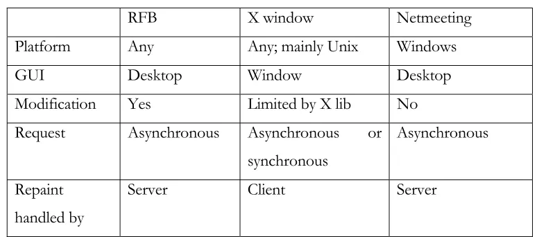
A functionally similar software is the Netmeeting™ from Microsoft™. Being a commercial-licensed software, Netmeeting works only with Windows operating system and lacks the ability of modification. On the contrary, VNC is based on General Public License (GPL) and is easy to adapt to any platform; furthermore, optional encodings can be applied and additional security improvement is available.
To achieve identical remote access, we can use X windows. Like RFB, X windows supports multiple operating system as well by using operating system specific X lib. Unlike RFB which treat desktop as a whole unit, X windows takes control of individual windows. By calling various functions in X lib, client can open a window, close a window and modify properties of a window; also, event handling is done with X lib. As a result, more message types are used in X windows than in RFB. In fact, besides configuration messages, only four major message types are used in RFB. They are rectangle update request message, pointer message, keyboard message and rectangle bitmap message. The first three are sent by client and the last is sent by server. In X windows, client has direct and thorough control of a single window.
RFB X window Netmeeting Platform Any Any; mainly Unix Windows
GUI Desktop Window Desktop Modification Yes Limited by X lib No
Request Asynchronous Asynchronous or synchronous
Asynchronous
Repaint handled by
Server Client Server
Table 4 Comparison between RFB, X window and Netmeeting
Encoding
To represent a rectangle bitmap for update, a variety of encoding methods are applied [6]:
First, there is raw encoding, where each pixel is represented by a bitstring of certain length. Because no compression is made, the raw encoding consumes most bandwidth.
Second, there is the RRE encoding. For the rectangle, a background pixel value is chosen; a tuple <v, x, y, w, h> is used to represent a subrectangle at position (x, y) that has a single pixel value v and width w and height h. Altogether, the background pixel value, a number N and N following tuples encode a rectangle area. Note that some types of bitmaps are encoded better in raw encoding (e.g. images) than in RRE encoding while some types of bitmaps are encoded better in RRE encoding (e.g. simple geometry shapes with single background).
Because in RRE, a rectangle is either encoded in RRE or raw, by limiting the maximum size of rectangles to 255x255 as in CoRRE, a good compression can be achieved.
The fourth encoding method is Hextile. In Hextile encoding, rectangles are divided into 16x16 tiles starting from top-left corner of each rectangle; each tile is either raw encoded or CoRRE encoded. To get better compression, a tile with a background pixel value same as previous tile can leave it background pixel value unspecified.
All implementations of RFB protocol must support raw encoding and raw encoding is the default encoding method if no configuration negotiation is performed between client and server. As shown in the details of the encoding methods, all encoding methods above are lost-less and can not achieve the same high compression rate as JPEG-like encodings in many cases. But the point is that the encoding methods are chosen in RFB protocol in such a way that the client needs minimum computer power to decode, as with the above encoding methods.
Copy Rect Optimization
Some of the encoding methods can make the data smaller than raw data; to further optimize usage of net connection bandwidth, a copy_rect scheme is used. It works like this: the server notices that a window has moved, instead of sending a rectangle bitmap, the server sends a copy_rect message indicating the original window position and size in desktop coordinates and new window position. The client receives the copy_rect message and simply copy and paste the window locally. The copy_rect message is much shorter than the rectangle bitmap that would be used otherwise.
Structure of VNC
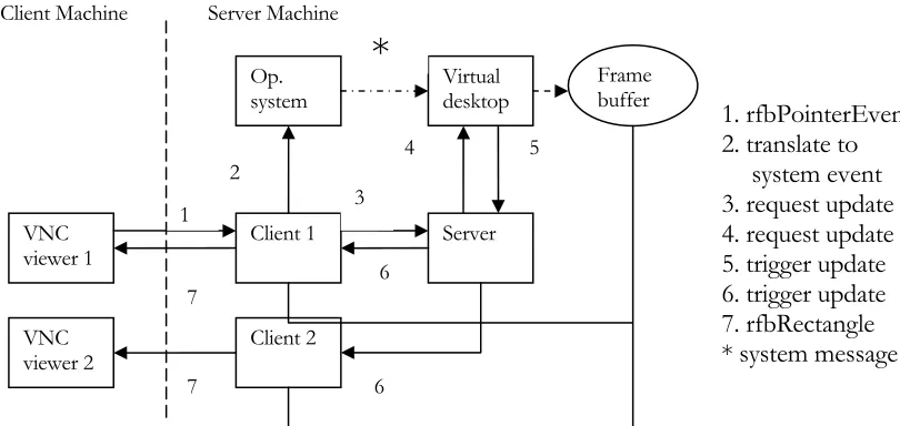
pointer message and reported to windows operating system. The operating system will process the pointer message and may update parts of the desktop of server machine. As a result, the virtual desktop intercepts the update of the desktop and records in a frame buffer. In the meantime, the client sends a request for update to the server. The server, in turn, sends a request to virtual desktop. The virtual desktop, after recording the update, makes the server trigger update for every client. Each client corresponding to each VNC viewer sends rfbrectangle back to viewer to update the virtual desktop window on client machine.
Figure 3 Steps in a pointer event handling in VNC (windows version)
Security in VNC
VNC service has authentication. At the initialization stage, the client provides a password encrypted with method D3DES, a variant version of DES (Data Encryption Standard). Encrypted client password is sent to server and compared against a password kept by server. If the passwords don’t match, the client is disconnected. In fact, the VNC server relinquished control completely to VNC client after connection is set-up, so the server must absolutely confirm the identity of the client. When VNC is modified to limit keyboard and pointer messages to a particular window, the strong authentication can be relaxed. However, the subsequent communications between client and server are not encrypted, meaning they are vulnerable to eavesdropping. This is in part due to the goal to make client very “thin”. To
VNC
viewer 1 Client 1 Server
VNC
viewer 2 Client 2
Op.
system Virtual desktop
1 3
*
Framebuffer Client Machine Server Machine
1. rfbPointerEvent 2. translate to
system event 3. request update 4. request update 5. trigger update 6. trigger update 7. rfbRectangle * system message
2 4 5
6
6 7
address this, secure channel must be used [7]. When combined with Bluetooth, the VNC gets “free” encryption support from Bluetooth.
Benefit from Virtual Desktop
Virtual desktop gives remote user a great tool to manage the resource on local system. In a sense, the local system treats remote user no different than a local user. As accessibility is concerned, the remote user just has the same privilege. However, additional feature can be added to limit remote user to just one window and its children windows.
Chapter 4 VNC Services on Bluetooth
For the following work, Digianswer Bluetooth cards and software suite Version 1.09 are used. The testing machines are two IBM Thinkpad laptops with 450 Mhz Pentium III processors. The software suite works in Windows 2000 and needs COM support.
Three steps are performed:
1. VNC service is appended to Bluetooth service database on server side and a stand-alone program is running on client side to discovery Bluetooth devices where VNC services reside;
2. Message filter is added to limit user input and screen update to a certain program window. This feature allows Bluetooth SDP to advertise a particular service from a particular program without unnecessary exposure of other resources; also this reduces the bits to transfer because only part of the screen needs to be updated.
3. Time-counters are added to record response time for performance test.
Bluetooth SDP protocol
In order to append VNC service to Bluetooth SDP, we are to go through an overview of Bluetooth SDP.
Figure 4 SDP Discovery Procedure
A SDP server maintains a database of local Bluetooth service and each service corresponds to a service record accessible by a handle. Contained in the response are handles to record(s) that match the types denoted in request. Subsequent operations on service records are carried out with the handles. The server must maintain the one-to-one relation between a handle and its corresponding service record at least during the session; the service must be aware of that the server is not obliged to maintain the one-to-one relation once the session is over.
A service record consists of several service attributes. Each attribute is an attribute ID/value pair and defines a characteristic of the service. An attribute ID is a 16-bit unsigned integer number to denote an attribute of the service represented by the service record. An attribute value is the value of the attribute and the format and the meaning of the value varies depending on the attribute ID.
Some attribute IDs have universal meaning through all service class, such as ServiceName, ServiceDescription, ServiceClassIDList, etc. [8]. Others attribute IDs have meanings that depend on what service class it belongs to. To determine the meaning of attribute IDs other than the common one mentioned above, you have to first evaluate the ServiceClassIDList attribute value to get the information of the service class. Basically, the value of ServiceClassIDList is a list of service classes IDs (assigned number by Bluetooth SIG) that the service belongs to, from the top basic class down to the most subclass.
SDP
The other attribute IDs are more specific for a certain service class. For example, for our newly defined service class (VNC class), an attribute ID 0x0200 is used to denote the VNC port number that is essential for VNC protocol.
Adding Service Record
The procedure to add a service record to local Bluetooth service database is as following [5]:
1. Get the pointer to local SDP object;
2. Call with the pointer the method CreateServiceRecord() to get a handle to newly generated record;
3. Put attribute ID/attribute value pair(s) in the record;
4. Save the record into the database.
The data contained in the service database are in the format of “data element”. A data element has two fields---a header field and a data field. The header field is in the most significant byte of a data element and consists of two parts---a 5-bit type descriptor and a 3-bit size descriptor. The type descriptor indicates the type of the data contained in the data field (integer, UUID, string or data sequence); the size of the data field either is described in the 3-bit size descriptor when the value of the descriptor is 0, 1, 2, 3 or 4 or takes the value of the 1, 2 or 4 bytes immediately following the header when the value of the descriptor is 5, 6 or 7 respectively [4]
Figure 5 Code fragment to create new service record (server side)
In the following code fragment, an attribute is added into the newly created service record. A attribute is represented as a DataElement as described in [4]. The attribute added in the following is a service class list.
dgaBTSDPProfile::IBTSDPProfilePtr m_pBTSDP; HRESULT hr;
//create a Bluetooth sdp profile object smart pointer
hr = m_pBTSDP.GetActiveObject(_uuidof(dgaBTSDPProfile::BTSDPProfile));
unsigned long m_nRH;
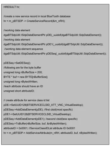
Figure 6 Code fragment to create new service record attribute (server side)
In above the service class ID list is added as an attribute in server Bluetooth database; to discovery the service, the client Bluetooth must provides a matching service class ID list when doing a service discovery.
HRESULT hr;
//create a new service record in local BlueTooth database hr = m_pBTSDP -> CreateServiceRecord(&m_nRH);
//working data element
dgaBTSdpUtil::ISdpDataElementPtr pDE(_uuidof(dgaBTSdpUtil::SdpDataElement)); //working data element
dgaBTSdpUtil::ISdpDataElementPtr pDE1(_uuidof(dgaBTSdpUtil::SdpDataElement)); //working data element sequence
dgaBTSdpUtil::ISdpDataElementPtr pDESeq(_uuidof(dgaBTSdpUtil::SdpDataElement));
pDESeq->SetDESeq();
//following are for the byte buffer unsigned long nBufferSize = 200; BYTE * buf = new BYTE[nBufferSize]; unsigned long nBytesWritten; //each attribute should have an ID unsigned short attributeID;
// create attribute for service class id list
pDE->SetUUID128(BTSERVICECLSID_ATT_VNC_VirtualDesktop); pDESeq->AddDataElement(pDE); //first clsid(most specific)
pDE1->SetUUID128(BTSERVICECLSID_VirtualDesktop); pDESeq->AddDataElement(pDE1); //second clsid(less specific) pDESeq->ToBuffer(nBufferSize, buf, &nBytesWritten);
attributeID = 0x0001; //ServiceClassIDList attribute ID 0x0001
Figure 7 Code fragment for service discovery (client side)
Note in above code fragment that the two GUIDs must match those in Figure 6 and in the correct sequence. After we have the handle to service record, we can inquiry other attributes in the service record with the handle.
Aside from universal attributes (service name, service ID, service class ID list, etc.), our VNC service needs other information to run (namely, IP address and port number). Actually, this information must be put into service record on server side as customer attributes.
Following are code fragments on client side and server side for a customer attribute (VNC port number).
HRESULT hr;
dgaBTAPI::BD_ADDR bd_addr;
//open SDP session to the specific bluetooth address hr = m_pSDP->OpenSDPSession(bd_addr);
dgaBTSDPProfile::PRecordHandle handles; unsigned short handlecount;
GUID guids[2];
guids[0] = BTSERVICECLSID_VirtualDesktop;
guids[1] = BTSERVICECLSID_ATT_VNC_VirtualDesktop; unsigned char uuidcount = 2;
hr =
m_pSDP->ServiceSearchRequest(bd_addr,guids,uuidcount,&handles,&handlecount);
//now the handles points to an array of record handles
//we are using the first one handles[0], assuming that one machine has only one VNC dgaBTSDPProfile::TRecordHandle vnchandle;
Figure 8 Code fragment to add a customer attribute (server side)
Figure 9 Code fragment to request an attribute (client side)
Clearly both client and server side rely on data element to exchange formatted information. While every data element is transferred in form of byte string, how it is interpreted (either call GetUINT16( ), GetString( ), or else) depends on the details in corresponding service class except for those used for universal attributes.
pDE->SetUINT16(m_nPort); //set data element to port number
pDE->ToBuffer(nBufferSize, buf, &nBytesWritten); // create a BYTE string for data element
attributeID = 0x0501; // attribute IDs in range of 0x000D-0x01FF are reserved
// attribute IDs in range 0x2000-0xFFFF are for customer attribute hr = m_pBTSDP-> AddServiceAttribute(m_nRH, attributeID, buf, nBytesWritten);
dgaBTSDPProfile::pbyte Attribute; unsigned short AttributeSize;
hr = m_pSDP->ServiceAttributeRequestSingle( bd_addr,
vnchandle,
0x0501, // attribute ID &Attribute,
&AttributeSize);
// construct a data element
pDE->FromBuffer(AttributeSize, Attribute, &n_bytes); // store the port
unsigned short port; pDE->GetUINT16(&port);
Before doing service discovery, the Bluetooth device on client side must have knowledge of the Bluetooth address of the devices in proximity. This is achieved with inquiry. In the software suite, the inquiry results are obtained in events.
Figure 10 Code fragment for inquiry event handler (from Digianswer software suite)
In above code, a typical event handler implements event interface and acts correspondingly. In above case, when an inquiry result event occurs, the raw_OnInquiryResult is called; inside raw_OnInquiryResult, Bluetooth address is extracted from the inquiry result as a parameter passed.
class ATL_NO_VTABLE CEventHandler : public CComObjectRoot,
public dgaBluetoothComObject::IBluetoothEvents { …
HRESULT Connect(IUnknown * pUnk); …
STDMETHOD(raw_OnInquiryResult) (dgaBluetoothComObject::BTInquiryResult InquiryResult); …
} …
HRESULT CEventHandler::Connect(IUnknown * pUnk) {
return AtlAdvise(pUnk, this->GetUnknown(), _uuidof(dgaBluetoothComObject::IBluetoothEvents), &m_dwCookie);
} …
STDMETHODIMP CEventHandler::raw_OnInquiryResult (dgaBluetoothComObject::BTInquiryResult InquiryResult) {
CBTAddress * pBTaddr = new CBTAddress(InquiryResult.Address, InquiryResult.ClassOfDevice); m_pDC->AddAddr(pBTaddr);
Modification to Original VNC
In original VNC, all resources on desktop are accessible for remote users as long as log-on. This mean only highly trusted remote users are supposed to use this VNC service. By limiting remote inputs to a single window, we expose only one window to remote user, thus lower the security requirement for remote users as other resources on desktop are out of reach from remote users.
To implement this, we are going to add some pieces of code to original winvnc source code, thanks to its open source policy.
Basically, for each VNC client there on server side is a thread with a loop and inside the loop it listens to a TCP port for formatted rfb- messages. Two categories of rfb- messages are defined in VNC protocol: user input (keyboard and pointer device) and protocol-related (encoding, pixel format, etc.). The action taken resides in the switch-case block.
First we have to check if the foreground window is the selected window or one of its children windows. Secondly, if it is the rfb-pointer message we are processing, we check if the window under the pointer is the selected window of one of its children windows. This is to make sure there is no unwanted side effect. Finally, if the two above test is passed, we can go on with ordinary message processing.
Figure 11 Code fragment to filter out pointer messages
case rfbPointerEvent:
HWND hf = GetForegroundWindow();
//match the parent of foreground window with chosen window do {
if(hf == m_client->m_hselectwnd ) break;
if(GetParent(hf) != NULL) hf = GetParent(hf); else
hf = GetWindow(hf, GW_OWNER); }while( hf != NULL );
//if not parents of the foreground window, then disconnect if(hf == NULL) {
connected = FALSE; break;
} … POINT pt; pt.x = msg.pe.x; pt.y = msg.pe.y;
HWND h = WindowFromPoint(pt); do {
if(h == m_client->m_hselectwnd ) break;
if(GetParent(h) != NULL) h = GetParent(h); else
h = GetWindow(h, GW_OWNER); }while( h != NULL );
if( h == NULL) break;
The mechanism above does limit the remote input to only particular windows (i.e. the chosen window and its children window or windows it owns), providing security benefits.
To mask out content on desktop other than the selected window and its children, another piece of code are added into the VNC server program. In the following code, a region is constructed from the selected window and its children, and this region is intersected with the region to be sent to clients.
Figure 12 Code fragment to limite update to only selected window
RECT myrect; vncRegion myrgn;
HWND hf = GetForegroundWindow(); HWND hp;
while( hf != NULL ){
// get RECT of the window if (!GetWindowRect(hf, &myrect)){ Kill();
return false; }
// add RECT to region myrgn.AddRect(myrect);
// stop when reaching the chosen window if( hf == m_hselectwnd)
break;
// get the owner or parent of the current window hp = GetWindow(hf, GW_OWNER);
if(hp == NULL) hp = GetParent(hf); hf = hp;
}
if (hf == NULL) { Kill();
return false; }
To prevent a client to minimize or close the selected window, a hook is added for this selected window. A hook is a function which is called during windows message processing; it can monitor the message being processed or modify the message.
Figure 13 Code fragment to add a hook to prevent a window from being close
PREVENTCLOSEHOOK_API BOOL PreventWindowClose(HWND hwnd, DWORD dwThreadId){
…
hCBTHook = SetWindowsHookEx(WH_CBT, CBTProc, hThisModule, dwThreadId); …
}
HRESULT CALLBACK CBTProc(int nCode, WPARAM wParam, LPARAM lParam) {
if(nCode < 0) {
return CallNextHookEx(hCBTHook , nCode, wParam, lParam); else {
switch(nCode){
case HCBT_MINMAX: return 1;
break;
case HCBT_SYSCOMMAND: if(wParam == SC_CLOSE){ return 1; // this eat the message }
else{
return CallNextHookEx(hCBTHook , nCode, wParam, lParam); break;
} default:
return CallNextHookEx(hCBTHook , nCode, wParam, lParam); }
Chapter 5 Performance Test and Result
To do performance testing, we add a small amount of code to the original vncviewer program (VNC client) source code.
There are two important things in vncviewer: the winproc function and the working thread. The winproc function responds to windows message by converting windows messages (keystroke messages and mouse messages) to rfb- messages. The working thread listening on a TCP port for rfb- message from VNC server.
To measure the response time, in winproc function a “keydown” or “mousebuttondown” message triggers an action to record current tick count; in working thread, a rfbRectUpdate message triggers an action to record the tick difference as response time.
Because a response to a remote user input could last in duration of time, as an animated menu does, a timer of period 5 seconds is also trigger when a “keydown” or “mousebuttondown” message occurs. The latest rfbRectUpdate message in 5 seconds is used to calculate response time. The amount of time 5 seconds is chosen in consideration of both responsive delay and human patience.
In addition to response time, the byte size of the update message received from server and the byte size of input message sent to server are also recorded.
Figure 17 Code fragment to measure response time void ClientConnection::StartTickCount() // called when user inputs
{
omni_mutex_lock l(m_tickMutex);
if(!m_waitingUpdate) {
m_tick = GetTickCount(); // tick for now m_RespT = 0;
m_waitingUpdate = true;
m_rspTimer = SetTimer(m_hwnd, IDT_RESPONSETIMER, 5000, NULL);
... } }
void ClientConnection::StopTickCount() // called when 5 seconds expires {
omni_mutex_lock l(m_tickMutex);
if(m_waitingUpdate) {
m_waitingUpdate = false;
KillTimer(m_hwnd,m_rspTimer); ...
} }
void ClientConnection::UpdateTickCount() // called when update rfb- message {
omni_mutex_lock l(m_tickMutex);
if(m_waitingUpdate) {
m_RespT = GetTickCount() - m_tick; // tick elapas this time so far ...
Five different times are recorded. The first one is the time needed for protocol initialization; the second one is the time to load the desktop screen the first time; the third one is the time to click on top menu and to wait for the menu list to appear; the fourth one is to press down arrow to select an menu item; the fifth one is to press enter to pop up the “about” dialog. The above 5 times are measured for 3 times and average is taken.
First, run the original winvnc program on server side and measure the response time from client side. The result is shown below.
Protocol initialization Initial frame load Click on top menu Select menu item
Pop up dialog
Time in ms 87 923 544 303 992 Received
bytes
66 48k 5k 2k 62k
Transferred bytes
77 20 22 16 16
Table 5 Response time (whole frame, no background)
Then, run the modified “single-window” winvnc program on the server side and measure the response time. The result is shown below:
Protocol initialization Initial frame load Click on top menu Select menu item Pop up dialog
Time in ms 80 704 581 277 988 Received
bytes
66 32k 5k 2k 62k
Transferred bytes
77 20 22 16 16
It is shown in the above two tables that the larger the received messages, the longer the response time. Comparing the last 4 times and the bytes numbers, it is obvious that the response time is not strictly proportional to bytes received; which indicates system needs time to process the VNC protocol messages and system messages.
Note that the by switching to “single-window” winvnc, the initial loading time is reduced because the size of the frame is reduced. However the following response times do not changed much because the updating size is independent of the total screen size.
The initial loading time is significantly longer when there is a background image, as it is shown below. The desktop background is a JPEG file “Paradise” coming with Windows 2000.
Figure 18 Initial loading times in different conditions
Intial load time for different conditions
0 2000 4000 6000 8000 10000 12000
whole desktop w/ background
whole desktop w/o background
single window
condition
ti
m
e
![Figure 2 Bluetooth protocol stack [4]](https://thumb-us.123doks.com/thumbv2/123dok_us/8928466.1845984/22.612.199.455.256.426/figure-bluetooth-protocol-stack.webp)