Volume 2, Issue 6, June 2013
Page 84
A
BSTRACTThe development of fuzzy logic has attracted considerable research interest over the past several decades. Several algorithms are put forwarded regarding design in controlling DC motor, still due to uncertainty and vagueness of data that are collected in the implementation phase, fuzzy logic becomes an inseparable area in control system. In this paper a detailed study has been made in a few applications of control system where fuzzy logic has been incorporated in controlling DC motor. This paper has been arranged in four phases where in the first phase fuzzy logic and fuzzy logic controller has been studied. The next phase discusses about the uncontrolled response of second order system. The third phase consists of a study the responses of conventional controller and fuzzy logic controller and a detail comparison has been discussed among uncontrolled response of second order system, conventional controller of DC motor and fuzzy logic controller taking settling time as a parameter in the final phase.
Keywords:fuzzy logic, control system, DC motor, conventional controller.
1.
I
NTRODUCTIONControl system consists of elements arranged in a planned manner where an effect is caused by each element to produce an output. Mathematically a relation can be made between this cause and effect. The application of control system includes the control of position, velocity, acceleration, temperature, pressure, voltage and current etc [9]. The data that are sensed in the various applications of control systems more or less have the characteristics of vagueness and ambiguity which depends on the devices through which sensors that have been used. Actually the physical factors of the devices are responsible for the degree of vagueness and ambiguity of data. Because of the presence of characteristics of ambiguity and vagueness in those data that are collected in various intermediate or final phases of control applications , though the degree of presence vary from devices to devices, it sometimes becomes harder to get the desired output . These problems can be said as fuzzy in nature. To overcome this problem, the application model can be defined formally in the fuzzy setting in order to take operations that can handle data uncertainty.
2.
F
UZZYL
OGIC AND ITSA
PPLICATIONSFuzzy logic began with the 1965 proposal of fuzzy set theory by Lotfi Al Zadeh. It has been applied to many fields, from control theory to artificial intelligence. Fuzzy logic also known as many-valued logic or probabilistic logic which has the property to deal with approximate reasoning rather than fixed and exact [1-5]. In compare with traditional logic they can have varying values, where binary sets deal with two-valued logic, true or false, fuzzy logic variables extend that truth value that lies in the interval value between 0 and 1. The extended concept of fuzzy logic to handle the concept of partial truth, where the truth value may lie between entirely true and entirely false [1]. In addition, when linguistic variables are applied, these degrees may be controlled by specific functions. Fuzzy logic and the probabilistic logic are mathematically analogous. Both have truth values ranging between 0 and 1; but conceptually not similar owing to different elucidations. Fuzzy logic relates to "degrees of truth", while probabilistic logic matches to "probability, likelihood"; as these differ, fuzzy logic and probabilistic logic yield different models of the same real-world situations. Both degrees of truth and probabilities range between 0 and 1 and hence may seem similar at first. For example, if “tall” is a set defined as heights equal to or greater than 7 feet, a computer would not recognize an individual of height 6 feet 11 inch as being the member of the set ‘tall’. But how do we assess the uncertainty in the following question: is the person nearly 7 feet tall? The uncertainty in this case is due to the vagueness or ambiguity of the adjective ‘nearly’. A 6 feet 11 inch person could clearly be a member of the set of “nearly 6 feet tall” people. In the first situation, the uncertainty of whether a person, whose height is unknown, is 6 feet or not is binary; the person either is or is not, and we can produce a probability assessment of that prospect based on height data from many people. But the uncertainty of whether a person, whose height is unknown, is 7 feet or not is binary. The degree to which the person
A Survey on the Application of Fuzzy Logic
Controller on DC Motor
Snehashish Bhattacharjee1, Samarjeet Borah2
1&2
Department of Computer Science and Engineering, Sikkim Manipal Institute of Technology,
Volume 2, Issue 6, June 2013
Page 85
approaches a height 7 feet is fuzzy. It is essential to realize that fuzzy logic uses truth degrees as a mathematical model of the vagueness phenomenon while probability is a mathematical model of ignorance. Fuzzy logic has the greatest success in control applications [1]. Many of the consumer products that we use today involve fuzzy control. Fuzzy logic is extensively used in machine control [18]. A fuzzy control system which is based on fuzzy theory—a mathematical system which scrutinizes analog input values in requisites of logical variables that takes on continuous interval between 0 and 1, in comparison to digital or classical logic, which controls on discrete parameters of either 1 or 0 (true or false, respectively). Fuzzy controllers are very straightforward conceptually by nature [4]. These include an input phase, a processing phase, and an output phase respectively. The input stage illustrates sensor or additional inputs, like switches, thumbwheels etc., to the suitable membership functions as well as the truth values. Each appropriate rule is invoked by the processing stage and generates a result for each, then merges the results each of the rules. Eventually, the output stage renovates the combined outcome back into a precise control output value. The most frequent shape of membership functions is triangular shape, although trapezoidal shape and bell curves are also worn, but the shape is usually not so important than the any other number of curves and their assignment. From three to seven curves are usually appropriate to envelop the essential assortment of an input value, otherwise the "Universe of Discourse" in fuzzy terminology. As explained earlier, the processing stage is depended on a collection of fuzzy-logic rules in the form of fuzzy ‘IF-THEN’ statements, where the ‘IF’ part is termed as the "antecedent" and the ‘THEN’ portion is termed as the "consequent".
2.1 Components of fuzzy systems
A fuzzy system is a computing framework based on the concepts of theory of fuzzy sets, fuzzy rules and fuzzy inference. Four components of fuzzy systems exist: a knowledge base, a fuzzification interface, an inference engine and a defuzzification interface.
The knowledge base consist of a rule base defined in terms of fuzzy rules, and a data base that contains the definitions of the linguistic terms for each input and output linguistic variable.
The fuzzification interface transforms the (crisp) input values into fuzzy values, by computing their membership to all linguistic terms defined in the corresponding input domain.
The inference engine performs the fuzzy inference process, by computing the activation degree and the output of each rule.
The defuzzification interface computes the (crisp) output values by combining the output of the rules and performing a specific transformation.
There are so many approaches in which fuzzy modeling can be done which are described in [6].
2.2 The direct approach to fuzzy modeling
In this approach, the system is first linguistically described, based on the expert‘s a priori knowledge. It is then translated into the formal structure of a fuzzy model following the steps proposed by Zadeh which have been described in [6].
Selection of the input, state, and output variables (structural parameters); Determination of the universes of discourse (structural parameters);
Determination of the linguistic labels into which these variables are partitioned (structural parameters); Definition of the membership functions corresponding to each linguistic label (operational parameters); Definition of the rules that describe the model‘s behavior (connective parameters);
Selection of an adequate reasoning mechanism (logic parameters); Evaluation of the model adequacy.
Besides these a number of approaches has been detailed in [6].
2.3 Approaches based on classic identification algorithms
A fuzzy model is a special type of nonlinear model. In this context, fuzzy modeling may be done applying classic nonlinear identification methods. These methods deal with an iterative, convergent, estimationof a set of numeric parameters, which are applied to a, usually pre-defined, model structure in order to approximate an expected behavior. In these fuzzy modeling approaches, the general structure of the fuzzy system (i.e., logic and structural parameters) is pre-defined, while the rest of the system (i.e., connective and operational parameters) is estimated.
2.4 Constructive learning approaches
Volume 2, Issue 6, June 2013
Page 86
begin by identifying a large fuzzy system—even systems with one rule for each training case—satisfying certain performance criteria.
2.5 Bio-inspired approaches: Neuro-fuzzy and evolutionary-fuzzy[6]
Artificial neural networks, evolutionary algorithms, and fuzzy logic belong to the same family of bio-inspired methodologies. Indeed, they model in different extents natural processes such as evolution, learning, or reasoning. The dynamic and continuously growing research on these subjects, have allowed identifying the strengths and weaknesses of each methodology, motivating a relatively recent trend to combine them in order to take advantage of their complementarities. In fuzzy modeling, such combinations have originated hybrid techniques known as neuro-fuzzy systems and evolutionary fuzzy modeling.
3.
FUZZY
LOGIC
APPLICATION
IN
DC
MOTOR
Conventional controllers were used to control the speed of DC motor for various industrial processes due to their simplicity in their operations [7].To control DC motor it is very obvious to know that DC motor is a second order system. So in this paper we shall first come across a general uncontrolled second order system and we shall calculate the response time. This response time will then be compared with conventional PID and fuzzy logic controller.
A second order can be defined as follows [11],
Ωm(s)=VT(s) (1)
Where Ωm(s) is the output and VT(s)is the input step signal. is the natural frequency of oscillation.
Now when <1, the uncontrolled response can be calculated as follows,
Figure 1 Uncontrolled response when <1
Similarly, when , the uncontrolled response is shown in the following figure [Figure 2],
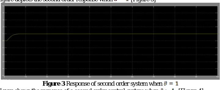
Figure 2 Uncontrolled response when The following figure depicts the second order response when [Figure 3]
Figure 3 Response of second order system when
Volume 2, Issue 6, June 2013
Page 87
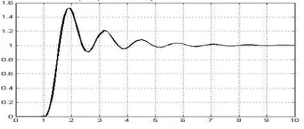
Figure 4 Response when
If the curves are observed properly it can be said that the settling time of the curve when is the minimum. A detailed comparison table has been given of all the second order response.
Table 1: Second order Un-controlled response time table
Second order response when Settling time (in secs)(Approximate)
< 1 Above 30
Above 100 15 Above 20
PID (proportional integral derivative) is one of those conventional controllers that have been used in earlier to design DC motor controller. Fuzzy logic based approach has been proposed and it has been proved in many times that motor parameters are controlled better than conventional approach [7]. The rule based decision approach makes fuzzy logic a unique domain to control a process that a human can control manually with expertise gained from previous experience. A good comparison study between conventional PID controller and fuzzy logic controller has been formulated in [7] where the authors have been successfully differentiated between these two controllers. The architecture of the fuzzy control [7] consists of four steps: fuzzification, fuzzy reasoning, defuzzification, fuzzy knowledge base and it is shown in the following figure [Figure 5]
Figure 5 Architecture model of fuzzy control
The response of the conventional proportional controller and PID controller is shown in the following figure that has been formulated in [7].
Figure 7 Step response of PID controller.
Fuzzification Fuzzy reasoning
Defuzzification
Fuzzy knowledge base
Error input Controller
Volume 2, Issue 6, June 2013
Page 88
Figure 8 Response of fuzzy logic controller.
The comparison of settling time and maximum overshoot for the above two controllers are also calculated in [8]
Table 2: Comparison of maximum overshoot and settling time
Controller Maximum overshoot(%) Settling time(sec)
PID controller 44.6 11.42
Fuzzy logic controller 7.21 7.78
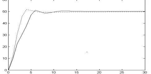
Another method PID like FLC [8] proposed where the performance between conventional PID and PID like FLC are compared which is shown in the following figure. The dotted line represents response of PID like FLC and solid line represents conventional PID.
Figure 9 Step response of armatured controlled DC motor using conventional and PID like FLC controllers. The rise time and the settling time for both the controllers which have been calculated in [8] are shown in below table.
Table 3: the rise time and the settling time for conventional PID and PID like FLC
Controller Rise time(sec) Settling time(sec)
Conventional PID 7 12
PID like FLC 4 5
Finally, the results based on the analysis carried out among all the techniques to control DC motor are consolidated in table 4. It depicts the comparison of all the responses in terms of settling time.
Table 4: Comparison table of all the responses
Responses Settling time (approximate in secs)
Volume 2, Issue 6, June 2013
Page 89
Conventional PID by D Sharma 11.42Fuzzy logic controller by D Sharmah 7.78
Conventional PID by Natshaeh et al 12
PID like FLC 5
4.
CONCLUSION
In this paper, a comparative analysis has been carried out between PID controller and fuzzy logic controller. Although it has been studied that conventional controller gives a very efficient result, but the time taken by the motor to become steady is very high. The analysis also shows that PID like FLC is better than conventional PID. So both the result suggests that fuzzy logic controller is better than conventional controllers. But in future it will be more desirable that the response time taken by the motor should be less than 5 seconds.
References
[1.] Timothy J. Ross, ‘Fuzzy Logic with Engineering and Application’, 3rd Ed, India, Wiley India Pvt. Ltd, ch 13, pp-408-433, 2010.
[2.] He Yikang, ‘Computer Simulation of AC Motor Vuying Speeds System’, Zhejiang UniversityPress, 1993 [3.] J.M. Mendel, ‘Fuzzy Logicsystems for engineering A tutorial,Proceedings’, IEEE, 83 3, 1995, pp. 345–377. [4.] R Jager, ‘Fuzzy logic in control’, PhD Thesis, Delft university, Holland, 1995.
[5.] K.J. Astrom, ‘Computer controlled systems’, Prentice-Hall, UK, 1990.
[6.] Sharma,’Designing and Modeling Fuzzy Control Systems’,International Journal of Computer Applications,Volume 16– No.1, February 2011,pp.46-53
[7.] R.Malhotra,T Kaur,G.S.Deol, ’Dc Motor Control Using Fuzzy Logic Controller’, International Journal Of Advanced Engineering Sciences And Technologies Vol No. 8, Issue No. 2, pp.291 – 296.
[8.] E. Natsheh, K.A. Buragga ‘Comparison between Conventional and Fuzzy Logic PID Controllers for Controlling DC Motors’, IJCSI International Journal of Computer Science, Vol. 7, Issue 5,pp.128-134 September 2010. [9.] Shakowat Zaman Sarkar, “A proposed Air–conditioning System using Fuzzy Algorithm for Industrial
Application” ICSEIEEE Proc. (2006) 832-834
[10.] M.Y. Hassan and F. Waleed Sharif, “Design of FPGA Based PID-like Fuzzy Controller for Industrial Applications”, IAENG, IJCS.34:2 (2005)
[11.] B.S Manke, ‘Linear Control Systems’ Khanna Publishers,Eleventh edition,2012,pp-131-140
[12.] P. C. Sen, ‘Principles of Electric Machines and PowerElectronics’. 2nd Ed,India Wiley India Pvt. Ltd, ch 04, 2009, pp.-121-200.
[13.] Kevin Warwick, ‘Introduction To Control Systems’,2nd Ed,World Scientific Publishing Co. Pvt. Ltd, Ch 09, 1996, pp.-274-305.
[14.] C. C. Lee, ‘FuzzyLogic In Control Systems : Fuzzy Logic Controller’,IEEE transactions on systems ,Man and Cybernatics vol-20 no-2 1990, pp.-404-418,.
[15.] W. Leonard, ‘Control of electrical drives’, Springer-Verlag, Berlin Heidelberg, New York, 1985.
[16.] Cavallo, R. Setola, F. Vasca, ‘Using Matlab, Simulink and control system toolbox: A practical approach’, Prentice Hall, Europe, UK, 1995.
[17.] J.L. Afonso, J. Fonseca, J.S. Martins, C. Couto, ‘Fuzzy logic techniques applied to the control of a three-phase induction motor’, ISIE’9 IEEE International symposium on Industrial Electronics, Guimara˜es, Portugal, July 7-11, 1997, IEEE, pp. 1179–1184.
[18.] Guanrong Chen, Young Hoon Joo, “Introduction to Fuzzy Control Systems”, raic.kunsan.ac.kr/paper/BOOK/book-2000-3.pdf , 2001.
AUTHORS
Volume 2, Issue 6, June 2013
Page 90
Networking etc. He has been doing the research-based project in Fuzzy-logic based motor controllers.