®
S
UPER
S
TACK
II H
UB
TR
N
ETWORK
M
ANAGEMENT
S
UPER
S
TACK
II H
UB
TR
N
ETWORK
M
ANAGEMENT
M
ODULE
I
NSTALLATION
G
UIDE
Introduction
The SuperStack II Hub TR Network Management module(s) provide real-time monitoring and control of Token Ring networks via the Simple Network Management Protocol (SNMP) and the Remote Monitoring Management Information Base (RMON MIB). When used in conjunction with the Transcend Enterprise Manager, the Hub TR NetworkManagement module(s) provide historical data, statistical analysis, remote packet captures, and traffic information for the entire network and all attached end users. Automatic port-mapping provides a continuous real-time diagram of all hub-to-hub interconnections, adapter card locations and addresses within the stack.
Modules have a DB9 Monitor/SLIP port which runs the RS-232 serial protocol for local console connection for configuring IP addresses, routing tables, and communication parameters. Access to the network management information is provided in-band via the network and also out-of-band via the Monitor/SLIP port.
The RMON module is equipped with 1 MB of RAM (4MB on Advanced RMON) for storage of historical data and can be user-upgraded to 5MB of RAM, (to 8MB or 12MB on Advanced RMON). A Reset button on the rear panel allows you to clear statistics stored in memory and reset the modules without losing the configuration parameters or without disrupting hub or ring operation.
Read further for installation, configuration, and local management instructions.
2 SUPERSTACK II HUB TR NETWORK MANAGEMENT MODULE INSTALLATION GUIDE
Installation
The Hub TR Network Management modules mount inside the SuperStack II Hub TR hubs. The module slides into a slot on the rear panel of the Hub TR. Refer to the Hub TR User Manual for the location of the module port. Before you install a Network Management module you must remove the filler plate from the back panel of the Hub TR. See below:1 Power down the Hub TR by either removing the AC power plug or RPS cord from the back panel.
2 Remove the filler plate by loosening the screws that hold it in place. You should keep the filler plate in a safe place in case you need to remove a Network Management module at a later date.
3 Remove the Network Management module from the protective anti-static bag while observing anti-static precautions (i.e. grounding strap).
4 Holding the Network Management module flat with the RS-232 port on the left, position the module into card guides located inside the module slot.
5 Slide the module into the card guides until the backplane connector slides into the corresponding connector inside the Hub TR.
6 Secure the module in place with the two screws from the filler plate.
7 Connect either the AC power plug or RPS cord.
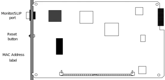
Figure 1 SuperStack II Hub TR Network Management Module
Reset button Monitor/SLIP
port
MAC Address label
Operation 3
Operation
The Hub TR Network Management modules operate when power is applied to the Hub TR. Each module has a Reset button which clears statistics but not configuration parameters. Be aware that resetting a module removes most stored information, including historical data, captured packets, statistics and any other data that has been collected via the Transcend program. Resetting the agent does not disrupt hub or ring operation and can be performed on a working network.To reset the module, use a small non-conductive instrument and press the reset switch. No other function of the network or hub is impaired when the switch is pressed. See Fig. 1.
Configuration
The purpose of the Hub TR Network Management module is to control the SuperStack II ™ Hub TR token ring hubs. Once you have completed the initial configuration procedure listed below, you can then use TELNET or Transcend to change the configuration settings.If you are using Transcend Enterprise Manager for NetView/6000®, HP OpenView®, or SunNet™ Manager, or Windows™ you have the following options:
■ In-band via IP routing
■ Out-of-band via serial (dial-up modem) or local connect with null
modem connection
The modules have the ability to manage devices on the network via an on-board device management program. Refer to the section on
Managing Devices for more information. Read the following instructions for configuring your Hub TR Network Management module.
4 SUPERSTACK II HUB TR NETWORK MANAGEMENT MODULE INSTALLATION GUIDE
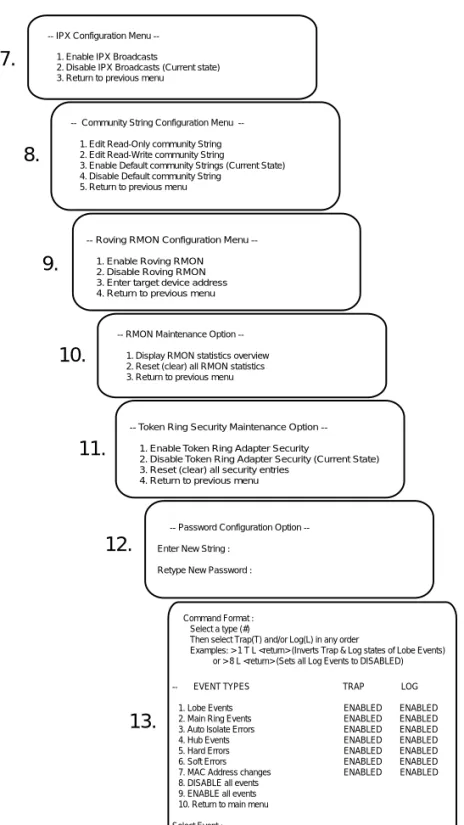
Menu Map The menu map below illustrates the configuration menus. Refer to the sections that follow for instructions on using these menus.
.
Internet Protocol Routing Configuration Menu --1. Display current routes
2. Add route 3. Set default route 4. Delete route 5. Return to previous menu Main Menu
--1. Device Vital Statistics
2. Internet Protocol (IP) Address Configuration Menu 3. Internet Protocol (IP Routing Configuration Menu 4. Communications Port Configuration Menu 5. Configure BOOTP for Token Ring interface 6. Device Management Menu
7. Configure IPX for Token Ring interface 8. Configure Community Strings 9. Configure Roving RMON Setup 10. RMON Maintenance
11. Token Ring Security Maintenance 12. Change Login Password 13. Trap/Log Configuration 14. Logout
Vital Statistics
--Token Ring MAC Address : 0002ba0038a5 SuperStack TR RMON Agent Flash Version : 3.05 ROM Version : 1.0.0
System Up time : 1 day 13 hrs 7 mins 31 secs
Intenet Protocol Address Configuation Meu
--1. COM1 SLIP xxxx xxxxxxxxxxxx 2. IP Routed Token Ring xxxxxxxxxx x xxxxxxxxxx 3. Return to Previous Menu
BOOTP Configuration Menu --1. Enable BOOTP
2. Disable BOOTP (Current State) 3. Reset Agent (BOOTP only started at boot) 4. Return to previous menu
Device Management Menu --1. Display All Hubs 2. Display Active Port Mappings 3. Display Event Log
4. Switch to Device Management Mode 5. Return to previous menu
Communications Port Configuration Menu --1. Modify BAUD Rate for COM1 (9600) 2. Set Modem Configuration String for COM1 (AT) 3. Configure Hardware Flow Control for COM1 (OFF) 4. Set Modem Detection Mode
5. Set SLIP/Console Mode 6. Return to previous menu
1.
2.
3.
4.
5.
6.
Configuration 5
Figure 2 SuperStack II Hub TR Configuration Menus
IPX Configuration Menu --1. Enable IPX Broadcasts
2. Disable IPX Broadcasts (Current state) 3. Return to previous menu
Community String Configuration Menu --1. Edit Read-Only community String 2. Edit Read-Write community String
3. Enable Default community Strings (Current State) 4. Disable Default community String
5. Return to previous menu
RMON Maintenance Option --1. Display RMON statistics overview 2. Reset (clear) all RMON statistics 3. Return to previous menu
Token Ring Security Maintenance Option --1. Enable Token Ring Adapter Security
2. Disable Token Ring Adapter Security (Current State) 3. Reset (clear) all security entries
4. Return to previous menu
Password Configuration Option --Enter New String :
Retype New Password :
-- EVENT TYPES TRAP LOG 1. Lobe Events ENABLED ENABLED 2. Main Ring Events ENABLED ENABLED 3. Auto lsolate Errors ENABLED ENABLED 4. Hub Events ENABLED ENABLED 5. Hard Errors ENABLED ENABLED 6. Soft Errors ENABLED ENABLED 7. MAC Address changes ENABLED ENABLED 8. DISABLE all events
9. ENABLE all events 10. Return to main menu Select Event :
Command Format : Select a type (#)
Then select Trap(T) and/or Log(L) in any order
Examples: > 1 T L <return> (Inverts Trap & Log states of Lobe Events) or > 8 L <return> (Sets all Log Events to DISABLED)
11.
7.
8.
9.
10.
12.
13.
Roving RMON Configuration Menu --1. Enable Roving RMON 2. Disable Roving RMON 3. Enter target device address 4. Return to previous menu
6 SUPERSTACK II HUB TR NETWORK MANAGEMENT MODULE INSTALLATION GUIDE
Checking Device Status
The Vital Statistics menu provides a current listing of statistics for the attached device. This is useful for inventory lists and configuring the BOOTP option.
1 Press the RETURN key until the System Logon screen appears.
2 Enter the default password: security.
3 Enter the number 1 at the Main menu prompt. The Vital Statistics screen appears.
The Device Vital Statistics screen is a static display that lists the Token Ring MAC address, the type of device, the Flash and EPROM version numbers, and the system up time in minutes and seconds.
Assigning IP address This procedure is necessary if you are using the Transcend Enterprise Manager (NetView/6000, HP OpenView, Sun NetManager, or Windows) or if you will be using IP in-band communication for your network management. An IP address can be configured locally using the console/terminal port or configured remotely using a BOOTP server. You will need to assign an IP address and a subnet address mask to
configure an IP address from the terminal connection.
1 Return to the Main menu.
2 Enter the number 2 at the Main menu prompt. The Internet Protocol Routing Configuration menu appears.
Vital Statistics
--Token Ring MAC Address : 0002ba0038a5 SuperStack TR RMON Agent
Flash Version : 3.05 ROM Version : 1.0.0
Configuration 7
3 Select 1 or 2 to configure an interface. Select 2 for in-band or 1 for out-of-band.
4 Enter the IP address followed by the net mask. Press 3 at the IP prompt to return to the Main menu. Configuring IP
Routes
Once you have assigned an IP address to your SuperStack II Hub TR Network Management module, you can view current routes, add routes, or delete routes using the Internet Protocol Routing
Configuration menu. Each agent requires a default route in connection with the management station. In most cases this is the IP address of the router interface on the agent’s ring. Follow the instructions below.
1 Return to the Main menu.
2 Enter the number 3 at the Main menu prompt. The Internet Protocol Routing Configuration menu appears.
3 Enter the number of the task you want to perform. You have five choices:
■ Display current routes—This displays the current routes with
destination IP address, destination netmask, and gateway IP address.
Internet Protocol Address Configuration Menu
--1. COM1 SLIP xxxx xxxxxxxxxxxx 2. IP Routed Token Ring xxxxxxxxxxx xxxxxxxxxx 3. Return to previous menu
Internet Protocol Routing Configuration Menu --1. Display current routes
2. Add route 3. Set default route 4. Delete route
8 SUPERSTACK II HUB TR NETWORK MANAGEMENT MODULE INSTALLATION GUIDE
■ Add route—This allows you to add a new route, subnet mask,
gateway, and routing metric. Enter the information on a single line, with a space between each of the fields.
■ Set default route—This allows you to enter a default setting for the
gateway IP address and the routing metric. Enter the information on a single line, with a space between each of the fields.
■ Delete route—This allows you to delete an IP address, subnet mask,
gateway from your routing table.
Press RETURN at any question mark prompt if you want to return to the previous menu without making a selection.
Configuring Communications Port
This section provides instructions for setting the communications parameters. The Monitor/SLIP port is referred to as COM 1 in the screens shown below. Follow the instructions below to set the communications parameters.
1 Return to the Main menu.
2 Enter the number 4 at the Main menu prompt. The Communications Port Configuration menu appears.
This menu allows you to change communication parameters. You have five choices:
■ Set the BAUD rate for COM1—The default setting is 9600 baud. ■ Set the modem configuration string—Sets the string of characters
sent to the modem from this port. This field defaults to “AT” which is a standard command string for modems. Refer to your modem documentation for the correct modem configuration string. Press RETURN to return to the previous menu.
Communications Port Configuration Menu --1. Modify BAUD Rate for COM1 (9600)
2. Set Modem Configuration String for COM1 (AT) 3. Configure Hardware Flow Control for COM1 (OFF) 4. Set Modem Detection Mode
5. Set SLIP/Console Mode 6. Return to previous menu
Configuration 9
■ Set the RTS/CTS hardware flow control setting—Specifies whether to
obey the “Ready-To-Send/Clear-To-Send” modem protocol. Default setting is off. Press RETURN to return to the previous menu.
■ Set the modem detection mode—Enables or disables auto-bauding.
Auto-bauding allows the modem to automatically determine its baud rate based on its own capability and the capability of the modem(s) with which it communicates. Turning off auto-bauding allows the modem to be hard-set. In this instance, a preset baud rate is entered into the modem.
■ Set the SLIP/Console mode—Used to configure a port as either a
SLIP (Serial Line Internet Protocol) interface or as a console.
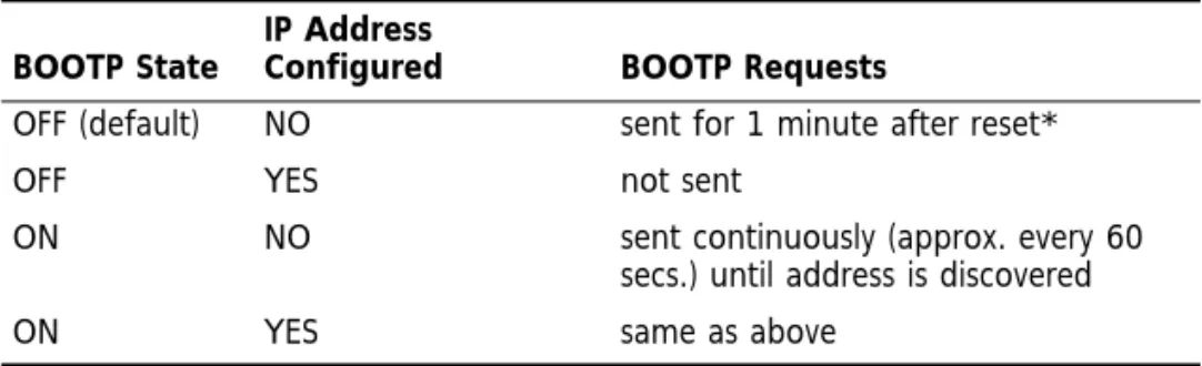
Configuring BOOTP Option
The BOOTP option allows you to enable or disable the bootstrap protocol. The BOOTP (bootstrap protocol) allows the hub to discover and learn its own IP address and routing table information. To configure a remote agent with the BOOTP option you will need a BOOTP server program. The module MAC address (found on the end of the module) must be entered in the BOOTP server program along with the corresponding IP address of the agent and its default route
information. This allows the BOOTP request from the agent to be logged by the BOOTP server which then supplies the return IP information.
* To auto learn address. Does not flood network with requests.
Follow the instructions below to set the communications parameters.
1 Return to the Main menu.
2 Enter the number 5 at the Main menu prompt. The BOOTP Configuration menu appears. Table 1 BOOTP States
BOOTP State
IP Address
Configured BOOTP Requests
OFF (default) NO sent for 1 minute after reset*
OFF YES not sent
ON NO sent continuously (approx. every 60
secs.) until address is discovered
10 SUPERSTACK II HUB TR NETWORK MANAGEMENT MODULE INSTALLATION GUIDE
This screen also informs you of the device’s current BOOTP state. You have three choices:
■ Enable BOOTP—Occurs after agent is rebooted. ■ Disable BOOTP—Occurs after agent is rebooted. ■ Reset Agent—Enables BOOTP at start up.
Managing Devices The Device Management menu allows you to configure hubs and ports that are part of the stack.
1 Return to the Main menu.
2 Enter the number 6 at the Main menu prompt. The Device Management menu appears.
You have the following four choices:
■ Display All Hubs—Lists the address, type, position, Ring In/Ring Out
connection, Agent type, and status of attached hubs.
■ Display Active Port Mappings—Lists the MAC address, location,
Netware address, and IP address of all active ports.
BOOTP Configuration Menu --1. Enable BOOTP
2. Disable BOOTP (Current State)
3. Reset Agent (BOOTP only started at boot) 4. Return to previous menu
Device Management Menu --1. Display All Hubs
2. Display Active Port Mappings 3. Display Event Log
4. Switch to Device Management Mode 5. Return to previous menu
Configuration 11
■ Display Event Log—Displays the time stamp and text of alert (system
up time).
■ Switch to Device Management Mode—Provides a list of commands
that allow you to view or modify various aspects of the device including hub, menu, port, route, system, trap, and version of device software.
Configuring IPX Interface
The IPX Configuration menu allows you to enable or disable IPX protocol broadcasts. IPX broadcasts are required if IPX is used as the transport protocol. This may be disabled if IP is used.
1 Return to the Main menu.
2 Enter the number 7 at the Main menu prompt. The IPX Configuration Menu appears.
This screen also informs you of the current IPX broadcast state. You have two choices:
■ Enable IPX broadcasts ■ Disable IPX broadcasts
Configuring Community Strings
The Community String Configuration menu allows you to configure SNMP community strings.
1 Return to the Main menu.
2 Enter the number 8 at the Main menu prompt. The Community String Configuration menu appears.
IPX Configuration Menu --1. Enable IPX Broadcasts
2. Disable IPX Broadcasts (Current state) 3. Return to previous menu
12 SUPERSTACK II HUB TR NETWORK MANAGEMENT MODULE INSTALLATION GUIDE
The screen also informs you of the current community string state. You have four choices:
■ Edit Read-only community string—Allows you to add a user defined
Read-only community string.
■ Edit Read-write community string—Allows you to add a user defined
Read-write community string.
■ Enable Default community strings—Allows you to enable Default
community string (Public/StarTek).
■ Disable Default community string—Allows you to disable Default
community string (Public/StarTek).
WARNING: Disabling the Default (Public/StarTek) community strings may effect operation of Transcend application.
Configuring Roving RMON
As bandwidth requirements increase, a stack of hubs initially configured as one shared ring may be split up into smaller rings that are
interconnected using Token Ring switching (such as the SuperStack II Switch 2000 TR). One method to achieve this segmentation would be to remove the cascade cable; however, this would not allow
management of the hubs not containing Network Management agent modules. The Roving RMON feature allows the ring to be split up by disconnecting the Token ring data path in the cascade cable, while retaining the management path.
A single Network Management agent module can be used to provide device management of up to 20 hubs, each supporting a separate ring. The single agent can be roved into any hub (and thus any ring) for detailed RMON statistics, error thresholding, and packet captures. The agent is roved (moved from hub to hub) using theRoving RMON
Community String Configuration Menu --1. Edit Read-Only community String 2. Edit Read-Write community String
3. Enable Default community Strings (Current State) 4. Disable Default community String
Configuration 13
Configuration menu. When Roving RMON is enabled, each hub is configured as a separate ring.
Use the Roving RMON menu to enter the address of the device with the agent you want to assign, as well as to enable and disable the
Roving RMON function.
1 Return to the Main menu.
2 Enter the number 9 at the Main menu prompt. The Roving RMON Configuration menu appears.
You have three choices:
■ Enable Roving RMON—Allows you to enable the Roving RMON
function. At this point, you may assign an agent to a ring.
NOTE: Enabling Roving RMON, disables the adapter lockout security function.
■ Disable Roving RMON—Allows you to disable the Roving RMON
function.
NOTE: Disabling Roving RMON does not re-enable adapter lockout security. See the Configuring Token Ring Security section below for switching on security.
■ Enter target device address—Displays the current targeted device
address and a command line for entering a new address. Obtain a list of all hub addresses using the Device Management menu (See “Managing Devices” above). Enter the new address as a 6 digit hex and press RETURN.
Roving RMON Configuration Menu --1. Enable Roving RMON
2. Disable Roving RMON 3. Enter target device address 4. Return to previous menu
14 SUPERSTACK II HUB TR NETWORK MANAGEMENT MODULE INSTALLATION GUIDE
RMON Maintenance Provides local ring statistics (including MAC frames, data frames, beacon events, soft errors) and RMON system information (including active captures, active host tables, active station table, Token Ring security table).
1 Return to the Main menu.
2 Enter the number 10 at the Main menu prompt. The Roving RMON Configuration menu appears.
You have two choices:
■ Display RMON statistics overview—Brings up the RMON Statistic and
System Overview screen, which includes the local ring statistics list and information about the system.
■ Reset (clear) all RMON statistics—Resets all counters including
remote Transcend sessions,
Configuring Token Ring Security
This function allows/disallows user access to a ring. Token Ring Security grants access based on the MAC address(es) known by the agent(s) in the ring.
1 Return to the Main menu.
2 Enter the number 11 at the Main menu prompt. The Token Ring Security Maintenance optionappears.
RMON Maintenance Option --1. Display RMON statistics overview 2. Reset (clear) all RMON statistics 3. Return to previous menu
Configuration 15
You have three choices:
■ Enable Token Ring Adapter Security—Turns the security function
on. In effect, any MAC address(es) unknown to the agent(s) are not granted access to the ring.
■ Disable Token Ring Adapter Security—Turns the security function off.
All MAC addresses are learned into the “allowed-in” table (default).
■ Reset security entries—Clears all security entries. Reset cannot be
selected when security is enabled.
Changing the Password
This section provides instructions for changing the password.
1 Return to the Main menu.
2 Enter the number 8 at the Main menu prompt. The Password Configuration Option menu appears.
You can enter up to 30 characters for a password. You must type the new password twice to change it.
Token Ring Security Maintenance Option --1. Enable Token Ring Adapter Security
2. Disable Token Ring Adapter Security (Current State) 3. Reset (clear) all security entries
4. Return to previous menu
Password Configuration Option --Enter New String :
16 SUPERSTACK II HUB TR NETWORK MANAGEMENT MODULE INSTALLATION GUIDE
Configuring Trap/Log Configuring Trap/Log allows you to perform two functions. First, you can control (enable/disable) the flow of event traps over the network. The trap function reports changes of state and error conditions to management stations. Second, you can specify whether or not an agent logs and displays an event.
NOTE: An agent must have the manager listed in its Manager Table before the agent can send a trap to that manager. Managers are automatically added after an SNMP request is made. By default, managers are “aged out” after 600 seconds of inactivity.
The log function enters a copy of the trap (in the form of a text description) in the agent’s Log Table. See Device Management above for displaying a log.
1 Return to the Main menu.
2 Enter the number 13 at the Main menu prompt. The Configuring Trap/Log menu appears.
3 At the Select Event command line enter the number of the event type (from the first column).
4 Type a T for Trap and/or an L for Log and press RETURN. The Trap and/or Log states invert for the event type specified.
-- EVENT TYPES TRAP LOG 1. Lobe Events ENABLED ENABLED 2. Main Ring Events ENABLED ENABLED 3. Auto lsolate Errors ENABLED ENABLED
4. Hub Events ENABLED ENABLED
5. Hard Errors ENABLED ENABLED 6. Soft Errors ENABLED ENABLED 7. MAC Address changes ENABLED ENABLED 8. DISABLE all events
9. ENABLE all events 10. Return to main menu Select Event :
Command Format : Select a type (#)
Then select Trap(T) and/or Log(L) in any order
Examples: > 1 T L <return> (Inverts Trap & Log states of Lobe Events) or > 8 L <return> (Sets all Log Events to DISABLED)
Memory Upgrade 17
Memory Upgrade
This section provides instructions for upgrading the memory in the SuperStack II Hub TR Network Management module.RMON Module The SuperStack II Hub TR Network Management module comes equipped with 1 MB of RAM installed on board. You can increase the memory to 5 MB by installing a 4 MB SIMM. Increased memory allows you to gather more information using the various software tools of the Transcend Enterprise Manager application. More and larger packet captures, longer historical files, and more in-depth statistical analysis are the direct results of more memory. The SuperStack II Hub TR agents were designed to accommodate standard-issue DRAM SIMMs. Follow the instructions below to install add-in memory.
The upgrade memory module is a standard part and is readily available via computer vendors. Ask for the following:
■ 1M x 32 bit DRAM, 72-pin SIMM, 70 nanosecond or less (speed
grade) or
■ 1M x 36 bit DRAM, 72-pin SIMM, 70 nanosecond or less (speed
grade)
Advanced RMON Module
The SuperStack II Hub TR Network Management module comes equipped with 4 MB of RAM installed on board. You can increase the memory to 8 or 12 MB by installing a 4 or 8 MB SIMM. Ask for the following:
■ 1M or 2M x 32 bit DRAM, 72-pin SIMM, 70 nanosecond or less
(speed grade) or
■ 1M or 2M x 36 bit DRAM, 72-pin SIMM, 70 nanosecond or less
18 SUPERSTACK II HUB TR NETWORK MANAGEMENT MODULE INSTALLATION GUIDE
Upgrading the memory
1 Power down the SuperStack II Hub TR 12 Port hub by removing the AC or DC power cord from the power source at the back of the unit.
2 Locate the Network Management module on the back panel of the SuperStack II Hub TR. Refer to the SuperStack II Hub TR User Manual.
3 Remove the two Phillips head screws that secure the module to the SuperStack II Hub TR.
4 Slide the module out of the Hub TR using the metal knob located in the middle of the module.
5 Place the module on a clean static-free surface.
6 Locate the DRAM memory expansion connector on the module. Refer to the cover illustration for the correct location.
7 Install the SIMM.
The DRAM memory expansion connector is keyed and will only accommodate the SIMM module in the correct position. If the SIMM module does not fit into the connector then it is installed incorrectly. Reverse the module and try again.
8 Snap the SIMM module into place so that the locking tabs on the expansion connector secure the module.
9 Reverse the procedure from Step 4 and power on the SuperStack II Hub TR.
Null Modem Cable Pin Assignments 19
Null Modem Cable
Pin Assignments
The following table lists the pin assignments for the null modem cable used to configure the SuperStack II Hub TR Network Management Module.
Pin DB-9 Signal Note Corresponding Pin DB-25
1 CD +5V 8
2 RxD Receive data 3
3 TxD Transmit data 2
4 DTR Data terminal ready 20
5 GND Ground 7
6 DSR Data set ready 6
7 RTS Request to send 4
8 CTS Clear to send 5
20 SUPERSTACK II HUB TR NETWORK MANAGEMENT MODULE INSTALLATION GUIDE
Technical
Information
Standards EMC
■ FCC 20780, Part 15J, Class A ■ VFG243 Level B (shielded cable) ■ EN 55022 Level A
■ CSA 108.8
Safety
■ EN60950:92 ■ UL1950
■ CSA22.2 No. 950
Electrical
■ Power Inlet: (SuperStack II Hub TR 12 or 24 Port) ■ Fuse Protection: (SuperStack II Hub TR 12 or 24 Port) ■ Power Supply: (SuperStack II Hub TR 12 or 24 Port)
RMON Module
■ Power Consumption: 15 W ■ Heat Dissipation/hour: 34 BTU
Advanced RMON Module
■ Power Consumption: 20 W ■ Heat Dissipation/hour: 68 BTU
Dimensions
■ Width: 7 1/2 in./ 19 cm ■ Depth: 10 1/2 in./ 26.6 cm ■ Height: 1 in./ 2.5 cm ■ Weight: 12 oz./ 340 g
®
3COM CORPORATION
5400 BAYFRONT PLAZA, P.O. BOX 58145 SANTA CLARA, CA 95052-8145
(408) 764-5000 PART NO. 99025