c
Sharif University of Technology, December 2009
Nonlinear Cyclic Analysis of Reinforced
Concrete Frames, Utilizing New Joint Element
S.SH. Hashemi
1, A.A. Tasnimi
1;and M. Soltani
1Abstract. In this article, a numerical model based on the layer approach is introduced for nonlinear cyclic analysis of two-dimensional reinforced concrete frames. The advantage of the proposed analytical procedure is that it takes the bond-slip, shear-slip and pull-out eects and, also, shears deformation in the joints into account. Bar and concrete stress-strain relations, the bond stress-slip relation and the shear stress-strain relation and, also, their cyclic behaviors are adopted as known specications. In the modeling, each frame is divided into two types of joint element and beam-column element. The eect of bond-slip has been considered in the formulation of a beam-column element by replacing the perfect bond assumption from the ber analysis method. Joint elements are formulated upon major behaviors including the pull-out of embedded longitudinal bars, shear and exural deformation of joint panels and shear slip in interface sections between joints and neighboring elements. The reliability of the method has been assessed through a comparison of numerical and experimental results for a variety of specimens tested under cyclic loading. A good agreement between experimental and analytical results is obtained for both cases of strength and stiness during the analysis.
Keywords: Nonlinear analysis; RC frames; Bond-slip; Joint element; Pull-out eect.
INTRODUCTION
Reinforced concrete frame structures in regions of high seismic risk particularly tend to develop inelastic deformations when subjected to strong earthquakes. Accordingly, a complete assessment of the seismic resistant design of these structures often requires a nonlinear analysis. Thus, a reliable numerical model that can simulate the hysteretic behavior of elements is necessary for predicting the nonlinear response of the frames. Much eort has been devoted in the last forty years to the development of models of the nonlinear analysis of Reinforced Concrete Frames (RCF). This re-search can be classied into three categories: behavior of steel bars and concrete material, interaction between bars and concrete and, nally, a numerical method for nonlinear analysis. In the eld of material behavior, numerous models have been proposed for steel and concrete materials based on experimental work and material tests. In the eld of interaction between
1. Department of Civil Engineering, School of Engineering, Tarbiat Modares University, Tehran, P.O. Box 14155-143, Iran.
*. Corresponding author. E-mail: [email protected] Received 20 January 2009; received in revised form 3 August 2009; accepted 21 September 2009
concrete and bars, researchers have proposed their models for a bond stress-slip relationship. Also, some researchers complemented and modied the previous models according to their new experimental works. In the beginning, a two-component model was proposed by Clough et al. [1] for the numerical analysis of RCF. After that, several concentrated and distributed plasticity constitutive models and modeling through a combination of sub-elements have been proposed [2-4]. The most promising model for the nonlinear analysis of reinforced concrete elements is, presently, ber section model or, in other words, layer model. In this model, the element is subdivided into longitudinal steel and concrete bers. The constitutive relation of the section is derived by integration of the response of the bers, which follows the uni-axial stress-stain relationship of materials. The ber model, basically, adopts the perfect bond assumption [5-6]. In many cases, this assumption causes a considerable dierence between experimental and analytical responses of the RCF [7]. Kwak and Kim [7] have taken the bond-slip eect into account by dening a modied monotonic stress-strain relation for the longitudinal bars in order to overcome this shortcoming. Limkatanyu and Spacone [8] have suggested a method based on a ber section for modeling a beam or a column reinforced concrete
ele-ment, but instead of the perfect bond assumption, they have considered that each beam or column element is a combination of one 2-node concrete frame element and several 2-node bar elements with bond interfaces. Meanwhile, the microscopic modeling of RCF and their elements, with and without bar-concrete interaction, in the nite element domain has been proposed. However, because of its cost, researchers prefer to suggest simpler methods.
Moreover, a variety of beam-column joint models have been proposed by researchers. Some of the earliest work simulating the inelastic response of RCF was based on calibration of the plastic-hinge formation within beam-column elements to introduce the inelastic action of the joint [9]. Another generation of joint models included decoupling the inelastic response of the beams, columns and joints to facilitate model calibration. One such model is the zero-length rota-tional spring element, which has been used in order to connect beam to column elements and, thereby, represent the shear distortion of the joint [10]. While these models provide a means of independently char-acterizing inelastic joint action with only a moderate increase in computational eort, this approach does not facilitate the development of objective and accurate calibration procedures. This approach requires that data from the experimental testing of beam-column joint sub-assemblages may be used to develop a one-dimensional joint moment-rotation relationship [11]. More recently, researchers have begun using continuum type elements to represent the response of reinforced concrete joints. This type of formulation greatly increases the computational eort of the analysis, but oers the potential for high-resolution, accurate and objective modeling of the joint region. This approach provides substantial additional computational eort to an analysis, but making two-dimensional dynamic analysis too time consuming for use by practicing engineers. In addition, a phenomenological model has been proposed by Lowes et al. [11]. In this approach, the joint element is modeled by assembling a series of one-dimensional components; each of them simulating one of the major behaviors of the joint element. This type of modeling needs a force-deformation relation for calibrating the dened components, which can be based on the results of experimental tests or empirical equations. The calibrating process in this model plays an important role in order to achieve good analytical accuracy.
The major sources of deformation in RCF are: exural rotation in beams and columns, shear deforma-tion of joints, including shear sliding, and bar-concrete interaction, such as bar's slip. In this paper, the behavior of frame elements arises from a combination of these deformation mechanisms. In order to achieve this goal, two types of element are modeled: One is
the beam-column element, which hereafter is denoted by \BCE" and the other is the joint element that is denoted by \JE".
BCE is selected according to Limkatanyu and Spacone [8] and generated based on the ber method, but the eect of bar-concrete interaction is imposed into equilibrium equations. JE is made up of a few mechanisms and sub-elements. This new JE is compat-ible with BCE for numerical modeling and overcomes many of the limitations in other previous proposed models. Four types of JE have been generated, depending on their location in RCF, as an exterior, corner, interior or footing connection.
MODELING OF REINFORCED CONCRETE ELEMENTS
Beam-Column Element
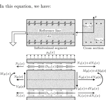
The free body diagram of an innitesimal segment, dx, of BCE is shown in Figure 1. Each BCE is introduced as a combination of one 2-node concrete frame element and n number of 2-node bars with bond interfaces. Limkatanyu and Spacone [8] proposed this element. Slippage is allowed to occur, because the nodal degrees of freedom of the concrete element and that of the bars are dierent. Based on small deformation assumptions, all equilibrium conditions are considered.
Considering axial equilibrium in the concrete element and steel bars, as well as the vertical and moment equilibriums in segment dx, leads to a matrix form of equations given by Equation 1:
@T
BDB(x) @bTDb(x) P(x) = 0: (1)
In this equation, we have:
Figure 1. Free body diagram of innitesimal segment of BCE and its components.
DB(x)=
n
D(x) : D(x)oT as the vector of BCE section forces; D(x)=fNB(x)MB(x)gT as the vector of
concrete element section forces; D(x)=fN1(x) Nn(x)gT as the vector of
bar axial forces; Db(x)=fDb1(x) Dbn(x)gT as the vector of
bond section forces; P(x)=f0py(x)0 0gT as the vector of
BCE force vector. n is the number of longitudinal bars in the cross section and py(x) is the value of external load in the y direction.
@B, @b are dierential operators and are dened in the
following forms: @B=
" @B 0
0 @B
#
; @B=
2 4
d dx 0
0 d2
dx2
3 5 ;
@B=
2 6 6 6 6 6 6 6 6 4 d
dx 0 0
0 d
dx 0
0 0 d
dx 3 7 7 7 7 7 7 7 7 5
nn
;
@b=
2 6 6 6 6 4
1 y1dxd 1 0
1 yndxd 0 1
3 7 7 7 7 5
n(2+n)
: (2)
yn is the distance of bar n from the section
refer-ence axis (Figure 1). The BCE section deforma-tion vector conjugate of DB(x) is dB(x) = fd(x) :
d(x)gT. In which d(x) = f"
B(x) B(x)gT contains
concrete element section deformations and d(x) = f"1(x) "n(x)gT contains the axial strain of the bars.
The displacement vector in the cross section of BCE is dened as u(x) = fu(x) : u(x)gT, in which
u(x) = fu1B(x) u2B(x)gT contains concrete element
axial and transversal displacements, respectively, and u(x) = fu1(x) un(x)gT contains the axial
displace-ments of the bars. From a small deformation as-sumption, the element deformations are related to the element displacements through the following relation:
dB(x) = @Bu(x): (3)
The bond slips of bars are determined by the following relation between the bar and concrete element displace-ments:
ubi(x) = ui(x) u1B(x) + yidu2Bdx(x); (4)
where ubi(x) is the bond slip between bar i and
sur-rounding concrete. By introducing the bond deforma-tion vector as db(x) = fub1(x) ubn(x)gT, Equation 4
can be written in the following matrix form:
db(x) = @bu(x): (5)
The weak form of displacement based nite element formulation is determined through the principle of sta-tionary potential energy. The BCE nodal displacement (U), which is shown in Figure 2, serves as primary element unknowns and the section displacement u(x) are related to it through the displacement shape function matrix (N(x)). The relation between nodal displacements and internal deformations can be written through the transformation matrix as Equation 6:
dB(x) = BB(x)U; db(x) = Bb(x)U;
BB(x) = @BN(x); Bb(x) = @bN(x): (6)
The nonlinear behavior of BCE is derived from the nonlinear relation between the section forces (DB(x),
Db(x)) and the section deformations (dB(x), db(x))
through section and bond stiness matrices (kB(x),
kb(x)). The section stiness matrix included the
axial and bending stiness of concrete element (EA(x) and EI(x)) and also the axial stiness of the bars (EnAn(x)). The bond stiness matrix is diagonal and
included the slope of the bond force-slip relationship of each bar (kbn(x)). By using the ber section method,
the section stiness matrix is derived. In this method, the stress-strain relationships of steel and concrete are needed. The bond stiness matrix is derived through the bond stress-slip relation and perimeter of each bar. From nite element formulation, the stiness matrix of BCE with the eect of bond-slip can be derived through the summation of two stiness matrices and can be written in the following form:
K = KB+ Kb=
Z
L
BT
B(x)kB(x)BB(x)dx
+ Z
L
BT
b(x)kb(x)Bb(x)dx: (7)
The relationship between the external load vector, the internal resisting force vector and the nodal displace-ment vector in the nonlinear analysis algorithm can be written in the following form:
KU=P Z
L
BT
B(x)DB(x)dx
Z
L
BT
b(x)Db(x)dx
= P Q = P (QB+ Qb); (8)
where K is the BCE stiness matrix, Q is the resisting force vector of the element and KB and Kb are the
element and bond contributions to the stiness matrix, respectively. Also, QB and Qb are the element and
bond contributions to the resisting force vector, respec-tively. At each load step of the nonlinear analysis, the resisting force vector of the section is driven according to existing deformations in each section of the element. Thereby, the resisting force vector of the element is derived by using numerical integration methods. The result of P Q is the residual force vector and converges to a zero vector after some iteration at each load step. Joint Element
In order to model the response of JE, two sub-elements and two signicant mechanisms have been considered. The sub-elements are a concrete and a reinforced concrete thick beam, in which the eects of shear and exural deformations have been considered based on the Timoshenko beam theory. In the Timoshenko beam theory, plane sections remain plane but are no longer normal to the longitudinal axis. The dierence between the normal to the longitudinal axis and the plane section rotation is the shear deformation. The two considered mechanisms are:
(a) Pull-out of a beam or column longitudinal bars embedded in the joint, which considers the pull-out failure.
(b) Shear-transfer at the BCE-joint interfaces, which considers the shear-slip.
The number of degrees of freedom at each side of JE is compatible with the degrees of freedom at the ends of the BCEs adjacent to JE. Thus, it will be possible to assemble the global matrix and vectors of RCF. In numerical modeling, depending on the location of JE in RCF, four types of JE can be dened through a combination of sub-elements and two signicant mechanisms considered here.
Reinforced Concrete Sub-Element
In a similar way described for BCE, the innitesi-mal segment of the Reinforced Concrete Sub-Element (RCSE) has a free body diagram similar to Figure 1.
In this sub-element, the eect of shear deformation is considered, based on the Timoshenko beam theory. Also, slippage has been allowed to occur. Considering axial equilibriums in the concrete part and steel bars, and vertical and moment equilibriums in the segment dx, leads to the matrix form of equations, given in Equation 1. The denitions in this equation are valid with the following:
D(x) = fNB(x)VB(x)MB(x)gT;
@B=
2 4
d
dx 0 0
0 d
dx 1
0 0 d
dx
3 5 ;
@b=
2 6 6 4
1 0 y1 1 0 0
1 0 y2 0 1 0
1 0 yn 0 0 1
3 7 7 5
n(3+n)
: (9) The RCSE section deformation vector conjugate of DB(x) is dB(x) = fd(x) : d(x)gT, in which d(x) =
f"B(x) B(x) B(x)gT contains axial, shear and
bending deformations of sections of the concrete el-ement, respectively. d(x) has a similar denition to that of BCE. The following displacements are dened at the sub-element level: u(x) = fu(x) : u(x)gT is the displacement vector along the RCSE in
which u(x) = fu1B(x) u2B(x) u3B(x)gT contains
axial, transversal and rotational displacements of the concrete element, respectively. u(x) has a similar denition to that of BCE. From a small deformation assumption, the element deformations are related to the element displacements through Equation 3. The following relation between the bars determines the bond slips of bars and concrete element displacements: ubi(x) = ui(x) u1B(x) + yiu3B(x): (10)
By introducing the bond deformation vector as db(x),
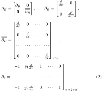
Equation 10 can be written in the form of Equation 5. The weak form of displacement based nite element formulation is determined through the principle of stationary potential energy. The RCSE nodal displace-ment vector is similar to that of BCE (Figure 3a). The section displacement vector is related to the nodal displacement vector through the matrix of shape functions. Then, the section deformations and bond slips could be determined through Equations 3 and 5.
The nonlinear behavior of RCSE is derived from the nonlinear relation between the section forces and the section deformations through section and bond stiness matrices. The section stiness matrix includes the axial, shear, and bending stiness of the concrete element (EA(x), GA(x) and EI(x)) and also the axial stiness of the bars (EnAn(x)). The bond stiness
Figure 3. Joint element parts and denitions.
matrix and method of calculation for these matrices and other calculations are similar to those described for BCE. The section shear stiness is derived from the shear stress-shear strain relationship.
By using the shape function matrix, the external load vector of this sub-element is derived from the external distributed loads (py1(x) and py2(x)), which
are shown in Figure 3a. The distributed loads are derived from the internal forces in the JE side sections, which are parallel to that sub-element based on the stress value in the concrete and steel bers of the mentioned side sections. The external load vector will be updated at each load step of the nonlinear analysis. Concrete Sub-Element
Concrete Sub-Element (CSE) is a plain concrete el-ement, which is a representative of a regular 2-node concrete frame element with three degrees of freedom at each of two ends (Figure 3b). The formulation of CSE is derived, based on the Timoshenko beam theory, the ber method and material behavior similar to the concrete part of RCSE. This sub-element is under the eect of external load, which could be determined on a basis similar to that of RCSE.
Pull-Out Mechanism
Referring to Figure 3c, the slippage of the bars can be dened in the form of Equation 11, if the nodal displacement vector related to pull-out behavior is dened as Uslip=U11 U21 U31 V11 :: Vn1
T.
slip = 2 6 6 4
s1 1
s1 2
: s1
n
3 7 7 5 =
2 6 6 4
1 0 y1 1 0 : 0
1 0 y2 0 1 : 0
: : : : : : :
1 0 yn 0 0 : 1
3 7 7 5 Uslip
= AslipUslip: (11)
In this equation, ynis the distance of the nth bar from
the reference line. The relationship between pull-out force and slip for the embedded nth bar in section 1 can be dened as f1
n = kslip n1 s1n, in which fn1is
pull-out force and k1
slip n is the slip stiness of the pull-out
behavior. This equation derives from the bond stress-slip relationship related to the pull-out behavior, the embedded length of the bar, conditions at the end of the bar and the perimeter of the bar cross section. The relationship between the pull-out force and slip of all bars in section 1 can be written in the following matrix
form:
fslip= k1slip slip; (12)
where k1
slip is a diagonal matrix that includes k1slip n
and fslip is the pull-out force vector according to the
slip vector.
The nodal force vector can be expressed in the following form:
Fslip= ATslipfslip= ATslipk1slipslip
= AT
slipk1slipAslipUslip= KslipUslip: (13)
From Equation 13, the pull-out stiness matrix related to section 1 can be written as AT
slipk1slipAslip. The
pull-out stiness matrix will be imposed into the stiness matrix of JE. Also, in order to calculate the resisting force vector related to pull-out behavior and impose it into the resisting force vector of JE, it can be written in the form of AT
slipfslip.
Shear Slip
According to Figure 3d, an interface shear component has been considered to represent shear slip and reduc-tion sliding shear. Based on the number of degrees of freedom in a shear direction on the specied side of JE, the shear slip can be dened as:
shear slip = U21 U23=
1 1 U21
U3 2
= Ashear slip
U1
2
U3 2
: (14)
If the shear force-shear slip relation at the side of JE can be dened as fshear slip = kshear slip shear slip,
the stiness matrix related to this mechanism and specied degrees of freedom can be written as AT
shear slipkshear slipAshear slip. Also, in order to
calcu-late the resisting force vector and impose it into the resisting force vector of JE, it should be written in the form of AT
shear slip fshear slip. The shear force-shear slip
relation is generated by using the shear stress-shear slip relationship [12]. The relevant shear force is the shear stress integration over the side surface of the JE. In this research, this eect is ignored because of its negligible value, which has a minor eect on the nonlinear response of the specimens.
Type of Joint Elements
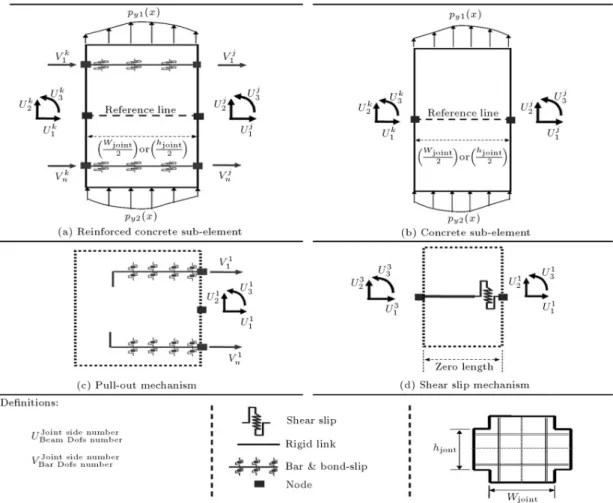
According to the location of the JEs in a two dimen-sional RCF and by using the specied mechanisms and sub-elements, four types of element have been dened and are illustrated in Figures 4 and 5. Type 1 of JE is basically modeled on pull-out and shears slip mechanisms that simulate the behavior of base and footing connections. Other types of JE have ve nodes,
Figure 4. Types 1 and 2 of joint elements in a two-dimensional RCF.
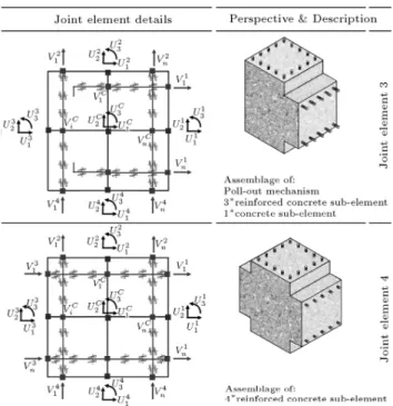
Figure 5. Types 3 and 4 of joint elements in a two-dimensional RCF.
comprising one node at the center of JE, and the others located at the center of the four edges of the perimeter. Type 2 of JE is used as the substitute of the corner connection in the frame, embracing two RCSEs, two CSEs and two pull-out mechanisms. Type 3, which can be used as an exterior connection in the frame, is the assemblage of three RCSEs, one CSE and one pull-out mechanism. Type 4 is a representative of an interior connection in which the pull-out mechanism is not considered because all longitudinal bars have been passed through the element. This type is a combination of four RCSEs.
MATERIAL BEHAVIORS
Concrete Cyclic Stress-Strain Relation
The monotonic envelope curve for conned concrete, introduced by Park et al. [13] and later extended by Scott et al. [14], is adopted for the compression region because of its simplicity and computational eciency. Also, it is assumed that concrete behavior is linearly elastic in the tension region before the tensile strength and, beyond that, the tensile stress decreases linearly with increasing tensile strain. Ultimate state of tension behavior is assumed to occur when tensile strain exceeds the value given in Equation 15.
"ut= 2
Gf
ft
ln
3 L
=(3 L); (15)
where L denotes the element length in mm and Gf is
the fracture energy that is dissipated in the formation of cracks of unit length per unit thickness, and is considered as a material property. ft is concrete
tensile strength. For normal strength concrete, the value of Gf=ft is in the range of 0.005-0.01 [15]. In
this research, the average value of 0.0075 is assumed for Gf=ft.
The rules suggested by Karsan and Jirsa [16] are adopted for the hysteresis behavior of the concrete stress-strain relation in the compression region. In addition, the unloading-reloading branches that always pass the origin, regardless of the loading history, are assumed in the tension region, because application of the introduced numerical model is limited to RC frame structures [17] (Figures 6a and 6b).
Cyclic Stress-Strain Relation of Steel Bars The Giure-Menegoto-Pinto model is adopted to rep-resent the stress-strain relationship of steel bars (Fig-ure 7). This model was initially proposed by Giuf-fre and Pinto [18] and later used by Menegoto and Pinto [19]. This model is modied by Filippou et al. [20] to include isotropic strain hardening. The model agrees very well with experimental results from cyclic tests of reinforcing steel bars.
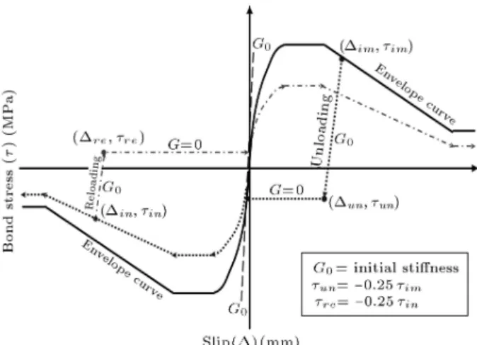
Cyclic Bond Stress-Slip Relation
Bond stress is referred to as the shear stress acting parallel to an embedded steel bar on the contact surface between the reinforcing bar and the concrete. Bond slip is dened as the relative displacement between the steel bar and the concrete. In this paper, two models have been used for a bond stress-bond slip relationship, one for the bond-slip behavior through the length of the BCE and another for bond-slip behavior through the length of the RCSE and the pull-out behavior
Figure 6. Concrete cyclic compressive and tensile stress-strain curve.
Figure 7. Cyclic stress-strain relation of steel bars.
of the bars in the joint elements. Among several models proposed by researchers, the one proposed by Eligehausen et al. [21] is adopted for both specied behaviors (Figure 8). In this model, the eect of many variables, such as spacing and height of lugs on the
Figure 8. Cyclic bond stress-slip relation.
steel bar, concrete compressive strength, thickness of concrete cover, steel bar diameter and end bar hooks have been considered. More details about unloading and reloading branches and bond strength degradation related to this model are given in [22].
Cyclic Shear Stress-Strain Relation of Joint The adopted model to represent the shear stress-strain of a joint is that proposed by Anderson et al. [23]. This model replicates cyclic degradation in strength, sti-ness (modulus) and energy dissipation for an unloading and reloading state of behavior (Figure 9).
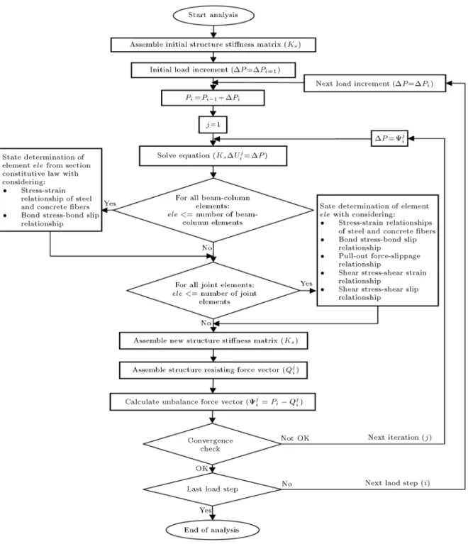
NONLINEAR ANALYSIS
In order to analyze RCF, based on the proposed method, a computer program has been developed. The solution of equilibrium equations is typically accom-plished by an iterative method through a convergence check. In this research, the Newton-Raphson method is used as nonlinear solution algorithms [24] (Figure 10).
Figure 9. Cyclic shear stress-strain relation.
Also, the Gauss-Lobatto method is used for numerical integration in which the number of integration points is equal to ve.
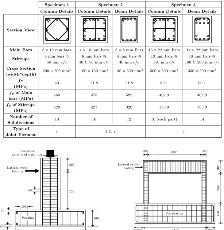
NUMERICAL VALIDATION
The ability and reliability of the proposed method has been demonstrated through verication of numerical and experimental results for a variety of tested speci-mens and the results for three specispeci-mens whose geome-try and details are shown in Figures 11-13 and listed in Table 1 are presented. The rst specimen is a column under lateral cyclic loading. The second specimen is a one bay one storey reinforced concrete frame, which is loaded laterally at the top with a displacement cyclic history. The third one is a subassembly of reinforced concrete frames and is comprised of beams, columns and joint elements under cyclic loading applied to the free end of the beam. In numerical modeling, beams and columns are subdivided into enough number of BCEs. Because the formulation is displacement-based and the response is dependent on element size, the length of BCE needs to be short enough. As a simple suggestion, the length of BCE can be selected equal or smaller than the average crack spacing in a beam or column. In these cases, convergence will be achieved in the numerical results. The equation given by CEB-FIP [25] is adapted for calculation of average crack spacing.
Specimen 1
This specimen is a column under constant axial load with a magnitude of 350 kN and lateral cyclic displace-ment loading at the free end. Table 1 and Figure 11 provide some details of this specimen that was tested by Qiu et al. [26]. In numerical modeling, this is modeled as a combination of 10 BCEs and type 1 of JEs. Figure 14 shows the analytical and experimental load-displacement responses with very good similarity and precision.
Specimen 2
This bare frame is modeled as a combination of BCEs, JE Type 1 and Type 2, some details of which are shown in Table 1 and Figure 12 and more details given in [27]. Columns have no constant axial load and the loading is only laterally. In numerical modeling, columns and beam are subdivided into 10 and 12 BCEs, respectively. This specimen was tested by Alin and Altin [27]. Figure 15 shows the analytical and experimental load-displacement history and good accordance for strength and stiness and their changes during cyclic loading.
Figure 10. Nonlinear solution owchart.
Specimen 3
This specimen is used from experimental tests reported by Chun et al. [28], a brief detail of which is listed in Table 1 and shown in Figure 13 and more details given in [28]. A 490kN of axial load was imposed on the column before applying a laterally cyclic load at the free end of the beam and remains constant during loading. In numerical modeling, the beam and the left and right parts of the column elements are subdivided
into 14, 10 and 10 BCEs, respectively. Also, type 3 of JEs is used as the intersection of the beam and column elements. Experimental and analytical results are shown in Figure 16. Experimental observations have shown that the nonlinear response of this specimen is complicated and aected by various behaviors such as shear deformation of the joint panel, pull-out of the longitudinal bars and exural deformation of the beam element. Nonetheless, the proposed method has good estimation for strength, stiness, and their
Table 1. Details of tested specimens.
Specimen 1 Specimen 2 Specimen 3
Column Details Column Details Beam Details Column Details Beam Details
Section View
Main Bars 8 12 mm bars 4 10 mm bars 8 8 mm Bars 16 22 mm bars 14 22 mm bars Stirrups 6 mm bars @
50 mm c/c
6 mm bars @ 40 & 80 mm c/c
4 mm bars @ 40 mm c/c
10 mm bars @ 150 mm c/c
10 mm bars @ 100 & 200 mm c/c Cross Section
(width*depth) 200 200 mm2 100 150 mm2 150 300 mm2 500 500 mm2 350 500 mm2 fC
(MPa) 40 21.8 21.8 60.1 60.1
fy of Main
bars (MPa) 460 475 592 402.9 402.9 fy of Stirrups
(MPa) 420 427 326 383.9 383.9
Number of
Subdivisions 10 10 12 10 (each part) 14 Type of
Joint Element 1 1 & 2 3
Figure 11. Geometry of the Specimen 1 (all dimensions in mm) [26].
degradation. CONCLUSION
In this article, a numerical model based on the layer approach is introduced for nonlinear cyclic analysis of two dimensional RCF. The advantage of the proposed analytical procedure is that it takes bond-slip, shear-slip and pull-out eects and, also, shears deformation
Figure 12. Geometry of the Specimen 2 (all dimensions in mm) [27].
in the joints into account. Formulation is displacement-based and shape functions are used in order to express internal displacements in terms of nodal displacement. To model each frame, two types of joint element and beam-column element are used. The eect of bond-slip is considered in the formulation of BCE by replacing the perfect bond assumption from the ber analysis method. JEs are formulated upon major behaviors including pull-out of embedded longitudinal bars, shear and exural deformation of the joint panel
Figure 13. Geometry of the Specimen 3 (all dimensions in mm) [28].
Figure 14. Experimental and analytical load-displacement response for Specimen 1.
Figure 15. Experimental and analytical load-displacement response for Specimen 2.
Figure 16. Experimental and analytical load-displacement response for Specimen 3.
and shear slip in the interface section between the joint and the neighboring element. Four types of JE have been generated, depending upon their location in the frame, as an exterior, corner, interior or footing connection.
In order to utilize the nonlinear cyclic analysis based on the proposed method, a computer program is developed. The reliability of the method is assessed through the comparison of numerical and experimental results for a variety of specimens tested under cyclic loading. Good agreement between experimental and analytical results is obtained for a variation of strength and stiness during analysis.
REFERENCES
1. Clough, R.W., Benuska, K.L. and Wilson, E.L. \In-elastic earthquake response of tall buildings", Pro-ceeding of Third World Conference on Earthquake Engineering, 2(2), pp. 68-89, New Zealand (1965). 2. Brancaleoni, F., Ciampi, V. and Di Antonio, R.
\Rate-type models for nonlinear hysteretic structural behavior", EUROMECH Colloquium, Palermo, Italy (1983).
3. Soleimani, D., Popov, E.P. and Bertero, V.V. \Non-linear beam model for R/C frame analysis", 7th ASCE Conference on Electronic Computation, St. Louis (1979).
4. Filippou, F.C., D'Ambrisi, A. and Issa, A. \Nonlinear static and dynamic analysis of reinforced concrete sub-assemblages", Report No. UCB/EERC-92/08, Earth-quake Engineering Research Center, College of engi-neering, University of California, Berkeley (1992). 5. Spacone, E., Filippou, F.C. and Taucer, F.F. \Fiber
beam-column model for nonlinear analysis of R/C frames: Part I. Formulation", Earthquake Engineering and Structural Dynamics, 25, pp. 711-725 (1996).
6. Mazars, J., Kotronis, P., Ragueneau, F. and Casaux, G. \Using multiber beams to account for shear and torsion applications to concrete structural elements", Computer Methods in Applied Mechanics and Engi-neering, 195, pp. 7264-7281 (2006).
7. Kwak, H.G. and Kim, J.K. \Implementation of bond-slip eect in analyses of RC frames under cyclic loads using layered section method", Engineering Structures, 28, pp. 1715-1727 (2006).
8. Limkatanyu, S. and Spacone, E. \Reinforced con-crete frame element with bond interfaces. Part I: Displacement-based, force-based, and mixed formu-lations", Structural Engineering, ASCE, 128(3), pp. 346-355 (2002).
9. Otani, S. \Inelastic analysis of RC frame structures", Journal of the Structural Division, ASCE, 100(ST7), pp. 1433-1449 (1974).
10. Alath, S. and Kunnath, S.K. \Modeling inelastic shear deformation in RC beam- column joints", Engineering Mechanics: Proceedings of 10th Conference: Univer-sity of Colorado at Boulder, Boulder, Colorado, 2, pp. 822-825 (May 21-24, 1995).
11. Lowes, L.N., Mitra, N. and Altoontash, A. \A beam-column joint model for simulating the earthquake response of reinforced concrete frames", Report No. 2003/10, Pacic Earthquake Engineering Research Center (PEER) (2004).
12. Walraven, J.C. \Fundamental analysis of aggregate interlock", Journal of the Structural Division, ASCE, 107(ST11), pp. 2245-2270 (1981).
13. Park, R., Kent, D.C. and Sampton, R.A. \Reinforced concrete members with cyclic loading", Journal of the Structural Division, ASCE, 98(7), pp. 1341-1360 (1972).
14. Scott, B.D., Park, R. and Priestley, M.J.N. \Stress-strain behavior of concrete conned by overlapping hoops at low and high strain rates", ACI Journal, 79(1), pp. 13-27 (1982).
15. Welch, G.B. and Haisman, B. \Fracture toughness measurements of concrete", Report no. R42, Sydney: University of New South Wales (1969).
16. Karsan, I.D. and Jirsa, J.O. \Behavior of concrete under compressive loading", Journal of Structural Division, ASCE, 95(ST 12), pp. 2543-2563 (1969). 17. Kwak, H.G. and Kim, S.P. \Cyclic moment-curvature
relation of an RC beam", Magazine of Concrete Re-search, 54(6), pp. 435-447 (2002).
18. Giure, A. and Pinto, P.E. \Il comportamento del cemento armato per sollecitazzioni cicliche di forte intensita", Giornale del Genio Civile, Maggio (1970). 19. Menegoto, M. and Pinto, P. \Method of analysis for
cyclically loaded RC plane frames including changes in geometry and non-elastic behavior of elements under combined normal force and bending", Symp. Resis-tance and Ultimate Deformability of Structures Acted on by Well Dened Repeated Loads, IABSE Reports, 13, Lisbon (1973).
20. Filippou, F.C., Popov, E. and Bertero, V. \Eect of bond deterioration on hysteretic behavior of reinforced concrete joints", Report No. EERC 83-19, Earthquake Engineering Research Center, University of California, Berkeley (1983).
21. Eligehausen, R., Popov, E. and Bertero, V. \Local bond stress-slip relationship of deformed bars under generalized excitations", Report No. UCB/EERC-83/23, Earthquake Engineering Center, University of California, Berkeley (1983).
22. Gan, Y. \Bond stress and slip modeling in nonlinear nite element analysis of reinforced concrete struc-tures", A Thesis Submitted for Degree of Master of Applied Science Graduate, Department of Civil Engineering, University of Toronto (2000).
23. Anderson, M., Lehman, D. and Stanton, J. \A cyclic shear stress-strain model for joints without transverse reinforcement", Engineering Structures, 30, pp. 941-954 (2008).
24. Bathe, K.J., Finite Element Procedures, Prentice Hall International, New Jersey, USA (1996).
25. Comite Euro International du Beton \CEB-FIP model code for concrete structures", Paris (1978).
26. Qiu, F., Li, W., Pan, P. and Qian, J. \Experimental tests on reinforced concrete columns under biaxial quasi-static loading", Engineering Structures, 24, pp. 419-428 (2002).
27. Alin, O. and Altin, S. \An experimental study on rein-forced concrete partially inlled frames", Engineering Structures, 29, pp. 449-460 (2007).
28. Chun, S.C. and Kim, D.Y." Evaluation of mechanical anchorage of reinforcement by exterior beam-column joint experiments", 13th World Conference on Earth-quake Engineering, Paper No. 0326 (2004).