Sharif University of Technology
Scientia IranicaTransactions B: Mechanical Engineering www.scientiairanica.com
Fluid-structure interaction analysis of a piezoelectric
exible plate in a cavity lled with uid
Y. Amini
a;b;, H. Emdad
aand M. Farid
a a. School of Mechanical Engineering, Shiraz University, Shiraz, Iran.b. Department of Mechanical Engineering, Persian Gulf University, Bushehr, Iran. Received 8 January 2013; received in revised form 6 September 2014; accepted 16 June 2015
KEYWORDS Fluid-structure interaction; Piezoelectric actuators; Smart materials; Large structural deformations.
Abstract. This study presents a numerical analysis of uid-structure interaction, the structure of which is a exible piezoelectric material. Piezoelectric materials are widely used in aero-elasticity and turbomachinery elds for vibration, utter, and noise control. In this work, a FSI benchmark is revised to contain the piezoelectric materials. The inuence of piezoelectricity on the oscillation of the structure and uid ow is considered. For validation, two benchmark problems are solved and the results of the present code are compared with those of previous work. Current results show that the piezoelectric behavior of a plate signicantly inuences the oscillation of the plate and the uid ow properties. © 2016 Sharif University of Technology. All rights reserved.
1. Introduction
Fluid-Structure Interaction (FSI) plays an important role in many engineering applications, such as suspen-sion bridges, aero-elasticity and utter, bio-mechanics, oil platforms, power lines, aircraft wings, and turbo-machinary.
There are two main computational categories for the modeling of FSI problems; the monolithic approach [1,2] and the partitioned (segregated) ap-proach [3,4]. In the monolithic apap-proach, the same primitive variables (usually velocity and pressure) are used for both the uid and solid domains; therefore, the governing equations of the uid and structure are solved simultaneously with a single solver. On the other hand, in the partitioned approach, the uid ow and the movement of the structure are solved separately by two distinct solvers. Since, in the *. Corresponding author. Tel.: +98 71 36133011;
Fax: +98 71 36473511
E-mail addresses: [email protected], and [email protected] (Y. Amini); [email protected] (H. Emdad); [email protected] (M. Farid)
monolithic approach, the nonlinear resulting equations arising from the coupled discretisation of the uid and the structure are solved as a whole, use of a coupling algorithm is not required, and is the main advantage of this approach. However, the monolithic solvers are computationally expensive and sometimes the matrix of the resulting algebraic system can be ill-conditioned, leading to diculties in solving these equations. The advantage of the partitioned approach is that it can precisely solve ow and structure equations by using dierent ecient techniques for each of them. Also, this approach uses separate meshes for the structure and the uid, which often require dierent mesh resolutions. On the other hand, in the partitioned simulations, development of stable and accurate coupling algorithms is required.
Piezoelectric materials have been extensively used as sensor and actuator devices in aeroelasticity and tur-bomachinery elds for vibration, noise, buet-induced vibration and utter controls. In these problems, structural vibrations are produced as the result of interaction between the uid ow and the structure. Therefore, all these problems are a type of FSI prob-lem.
Based on the authors' knowledge, regarding previ-ous studies in FSI problems with orthotropic piezoelec-tric materials, only piezoelecpiezoelec-tric and structural govern-ing equations are solved, and the uid ow is considered a pressure load [5] or calculated by the piston theory [6-9]. Therefore, uid structure interaction was not taken into account.
Bolzmacher et al. [10] introduced a novel micro-mechanical amplication unit for increasing the stroke of piezoelectric micro-actuators. In their study, only the equation of structure was numerically solved. In order to obtain a better estimate for the actuator per-formance and to optimize its design, they proposed that the uid-structure interaction between the piezoelectric actuator and the airow should be considered in the simulations.
Recently, piezoelectric materials have been used as energy harvesters, which convert aero-elastic vi-brations to electric energy [5,11-16]. Although these problems are of a FSI type, they were investigated by experimental analysis or a predened vibration was assumed in numeric simulation. A full FSI analysis has not yet been undertaken.
By development of FSI codes and software, it is possible to solve these problems without simplication in the uid ow and investigate them as a FSI problem. In this work, an FSI benchmark is revised to contain the piezoelectric materials. The inuence of dierent electric potentials on deformation of the structure and the uid ow is considered.
2. Governing equations 2.1. Fluid equations
The governing equations of the uid ow are the incompressible Navier-Stokes equations. Since, in the Arbitrary Lagrangian Eulerian method (ALE) formu-lation, the mesh nodes of the uid domain could be in motion, Navier-Stokes equations on a moving mesh should be used in the following form [17,18]:
r:v = 0; @v
@t + (v ^v) r:v = rp + r2v; (1)
where , v, p, and t are density, velocity, pressure, viscosity, and time, respectively, and ^v represent the mesh node velocity.
2.2. Piezoelectric equations
Some materials have the ability to convert mechanical energy into electrical energy and vice versa. This property is known as piezoelectricity. The direct piezoelectric eect is known as producing voltage by a material when it is subjected to stress. The inverse piezoelectric eect is that the crystal deforms when a voltage dierence is applied across it.
The momentum equation for a solid material is:
@@t2u2 = r:T; (2)
where T is the stress vector and u is the displacement of the solid material.
The electric displacement (electric ux density) vector, Di, satises Gauss law as:
Di;i= 0: (3)
The constitutive relations for a linear piezoelectric material are dened as:
Tij = cEijklSkl ekijEk;
Di= eiklSkl+ "SijEk; (4)
where S is the strain vector, E is the electric eld vector, c is the elasticity matrix, e is the piezoelectric stress matrix, and " is the dielectric matrix (evaluated at constant mechanical strain), respectively.
By substituting these constitutive relations in the momentum equations and Gauss law and using the following equations:
Ei= ';i; (5)
Sij =12(ui;j+ uj;i); (6)
the nal set of partial dierential equations with me-chanical displacement and electric potential as primary dependent variables is obtained as:
u = r:[c : ru] + r:[e:r']; (7)
r:[e : ru] r:[":r'] = 0; (8)
which can be shown in the following index notation for constant material properties:
ui= cEijkluk;lj+ ekij';kj; (9)
ekijui;kj "Skj';kj = 0: (10)
By using nite element discretization, the following system of coupled equations are derived for each ele-ment [9]:
[M] [0] [0] [0] f fug'g
+
[C] [0]
[0] [0] f _ugf _'g
+
[K] [Kz]
[Kz]T [Kd] fugf'g
=
fF g fLg
; (11) where [M], [C], and [K] are the element mass matrix, the element structural damping matrix, and the ele-ment stiness matrix, respectively; Kz is the
piezo-electric coupling matrix, Kd is the element dielectric
permittivity coecient matrix, fug is the displacement vector and f'g, fF g, and fLg are the electric potential (voltage), structural and electrical load vectors, respec-tively.
2.3. Fluid-structure coupling and mesh motion Usually, Lagrangian formulation, where each individual node of the computational mesh moves with the asso-ciated material particle during the motion, is used in solid mechanics. The Lagrangian description permits an easy tracking of free surfaces and interfaces among dierent materials. However, it requires remeshing processes for large distortions of the computational mesh.
Flow solvers often use an Eulerian description, in which the computational mesh is xed and the uid moves relative to the grid, and large distortions in the uid motion are handled by this description. In the geometrically xed uid domain, this approach works well, but, diculties arise when the boundaries of the uid domain change. Fluid structure interaction is the most well-known example for moving boundaries in the uid domain. In FSI problems, deformation in the solid material moves the uid mesh points at the uid-structure interface.
Various techniques have been proposed for sim-ulation of the moving boundaries in the uid domain. ALE is the most popular method employed for tracking uid moving boundaries [17,19]. In an ALE method, some parts of the mesh can be moved with the associated material particles, such as the Lagrangian approach. Other parts of the mesh are xed similar to the Eulerian approach. Although this method has low computational cost and it is accurate, for large deformations or movement of solid material, uid elements tend to become ill-shaped and the solution accuracy reduces. Some alternatives to the ALE method are the immersed boundary method [20,21], ctitious domain method [22], and the mortar nite element method [23]. In contrast to the ALE technique, other methods use xed uid meshes, and, hence, can simulate large deformation of solid material without mesh folding in the uid domain. However, since the ALE method captures the uid-structure interface accurately, it has the ability to maintain high-quality meshes near the structure's interface. In the current study, a partitioned FSI solver with ALE formulation for the ow solver is used.
At the interface of the uid and structure do-mains, interaction is considered by transferring the uid ow stress to the structure and the structural displacements to the uid ow. Also, it is assumed that the uid always remains in contact with the structure. Therefore, the compatibility of the displacement and no-slip condition requires that:
TS:n = TF:n; (12)
uS = uF: (13)
In the ALE approach, the uid internal mesh should be deformed in response to the uid-structure interface
displacements. However, the deformation of the uid domain is unknown and it should be found in terms of structural deformation. In the present work, the Laplacian operator is used for mesh motion in the uid domain. In this method, mesh velocity, ^v, is computed by solving the Laplacian equation as:
r: (r^v) = 0; (14)
where is the diusion coecient. The boundary conditions for this equation are:
^v = (du
dt for uid solid interface boundary
0 for other boundaries
) :
(15) 3. Results and discussion
Validation of the present work is achieved by analyzing two benchmark problems. The rst is a piezoelectric problem and the other a uid structural interaction problem. The results show that in the current study, the piezoelectric problem and the FSI problem are solved correctly. In order to investigate the eect of piezoelectricity on the uid ow and deformation of the structure, the elastic material in the FSI benchmark is replaced by a piezoelectric material.
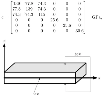
3.1. Piezoelectric bimorph actuator plate The geometry of a piezoelectric bimorph plate is shown in Figure 1.
In this case, an electric potential equal to 50 voltages is applied to the bottom and top faces of the plate, and the intermediate surface is set to zero voltage. The length (L), width (l) and thickness of this rectangular plate are 25 mm, 12.5 mm, and 2.5 mm, respectively. Boundaries are considered to be simply supported. Also, its material constants are [24]:
c = 2 6 6 6 6 6 6 4
139 77:8 74:3 0 0 0
77:8 139 74:3 0 0 0
74:3 74:3 115 0 0 0
0 0 0 25:6 0 0
0 0 0 0 25:6 0
0 0 0 0 0 30:6
3 7 7 7 7 7 7 5
GPa;
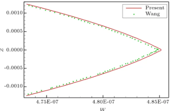
Figure 2. Through-the-thickness variation of the deection, W , at the plate center.
Figure 3. Contour of the through-the-thickness variation of the deection, W , at the center of plate.
e = 2 6 6 6 6 6 6 4
0 0 5:2
0 0 5:2
0 0 15:1
0 12:7 0
12:7 0 0
0 0 0
3 7 7 7 7 7 7 5
C m2;
" = 2
413:06e 90 13:06e 90 00
0 0 15:1e 9
3
5 F
m: In Figure 2, the through-the-thickness variation of deection, W , at the plate center is shown and the results are compared with those of Wang [24]. From this gure, it is clear that in the present analysis, modeling of the piezoelectric material is done properly. Figure 3 shows the contours of deection, W .
3.2. Oscillation of a vertical exible plate in a cavity
The FSI part of the current work is validated by analyzing the oscillations of a vertical exible plate in a cavity lled with uid. The geometry of this case is shown in Figure 4.
Figure 4. The geometry of FSI benchmark problem.
Figure 5. Comparison between the current study and previous results.
The length, thickness and width of the plate are 1.0 m, 0.06 m and 0.4 m, respectively. Young's modulus of elasticity (E) and the density of the plate (s) are
2:5 106 Pa and 2550 kg/m3, respectively.
The uid has the following material properties: uid density, f = 1 kg/m3, and dynamic viscosity of
the uid, f = 0:2 kg/m3. The plate is excited with a
uniformly distributed load of 30 N/m within the rst 0.5 sec. Namkoong et al. [25] and Gluck et al. [26] solved this problem with a time step equal to 0.1 sec.
In Figure 5, the horizontal displacement of the free end of the plate obtained by Namkoong et al. and the current solver are compared. From this gure, it is evident that when the time step is chosen the same as that in the work of Namkoong et al., the results of the current study agree with those obtained by them. But, this time step is very large for this problem. By reducing the time step, the results change and we propose that for later studies, results should be compared with a time step of 0.02 sec or less.
3.3. Oscillation of a vertical piezoelectric plate in a cavity
For investigation of the eect of piezoelectricity on structural deformation and the ow eld, the elastic plate in the previous FSI problem is replaced by a plate
Figure 6. Horizontal displacement of the free end of the piezoelectric plate for dierent voltages.
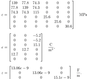
made of piezoelectric material. The problem geometry, length, width and thickness of the piezoelectric plate and the uid parameters are chosen similar to those of the preceding case. The material constants of the piezoelectric plate are considered to be:
c = 2 6 6 6 6 6 6 4
139 77:8 74:3 0 0 0
77:8 139 74:3 0 0 0
74:3 74:3 115 0 0 0
0 0 0 25:6 0 0
0 0 0 0 25:6 0
0 0 0 0 0 30:6
3 7 7 7 7 7 7 5
MPa;
e = 2 6 6 6 6 6 6 4
0 0 5:2
0 0 5:2
0 0 15:1
0 12:7 0
12:7 0 0
0 0 0
3 7 7 7 7 7 7 5
C m2;
" = 2
413:06e 90 13:06e 90 00
0 0 15:1e 9
3
5 F
m: In this problem, the voltage at the right face of the plate is set to zero, but, various voltages are applied at the left face of the plate.
Figure 6 presents the horizontal displacement of the free end of the piezoelectric plate for dierent voltages (0, 100, 200 and 300 volts). By applying these voltages to the piezoelectric plate, the maximum deection of the plate in the positive x direction is reduced, but, no signicant eect on maximum deection in the negative x direction is seen. The reason for this phenomenon is that the applied voltages tend to deform the plate in the negative direction of x. For electric potential equal to 200 V, the deforma-tions of the left face of the plate are shown for dierent times in Figure 7. This gure reveals that this high voltage does not activate the higher mode shapes in the plate.
Figure 7. Deformations of left face of the plate at electric potential equal to 200 V for dierent times.
Figure 8. Velocity contours for electric potential of 200 V and time of 0.6 sec.
Figure 9. Pressure contours for electric potential of 200 V and time of 0.6 sec.
Figures 8 and 9 show the velocity and pressure contours for electric potential of 200 V and time of 0.6 sec, respectively. As shown in Figure 8, at the top of the plate, the induced velocity in the uid domain has its maximum value.
4. Conclusion
In the present work, an FSI benchmark problem was revised to contain the orthotropic piezoelectric mate-rial. In this problem, dierent electric voltages were applied to the piezoelectric material and the vibration of this plate at dierent times was considered. It
was observed that by increasing the electric potential from zero, maximum displacement in the positive x direction is reduced. However, the inuence of the electric potential on the plate deection is decreased by increasing the electric potential. Therefore, the piezoelectric actuator suppresses the vibration of the plate, which is caused by uid ow.
References
1. Blom, F.J. \A monolithical uid-structure interaction algorithm applied to the piston problem", Comput. Methods Appl. Mech. Eng., 167(3-4), pp. 369-391 (1998).
2. Dunne, T., Rannacher, R. and Richter, T. \Numeri-cal simulation of uid-structure interaction based on monolithic variational formulations", Numerical Fluid Structure Interaction, Springer (2010).
3. Piperno, S. and Farhat, C. \Partitioned procedures for the transient solution of coupled aeroelastic problems -Part II: energy transfer analysis and three-dimensional applications", Comput. Methods Appl. Mech. Eng., 190(24-25), pp. 3147-3170 (2001).
4. Piperno, S., Farhat, C. and Larrouturou, B. \Parti-tioned procedures for the transient solution of coupled aroelastic problems. Part I: Model problem, theory and two-dimensional application", Comput. Methods Appl. Mech. Eng., 124(1-2), pp. 79-112 (1995).
5. Dunnmon, J.A., Stanton, S.C., Mann, B.P. and Dow-ell, E.H. \Power extraction from aeroelastic limit cycle oscillations", J Fluids Struct., 27(8), pp. 1182-1198 (2011).
6. Moon, S.H. \Finite element analysis and design of con-trol system with feedback output using piezoelectric sensor/actuator for panel utter suppression", Finite Elements in Analysis and Design, 42(12), pp. 1071-1078 (2006).
7. Kouchakzadeh, M.A., Rasekh, M. and Haddadpour, H. \Panel utter analysis of general laminated com-posite plates", Compos. Struct., 92(12), pp. 2906-2915 (2010).
8. Li, F.-M. \Active aeroelastic utter suppression of a supersonic plate with piezoelectric material", Int. J. Eng. Sci., 51(0), pp. 190-203 (2012).
9. Allik, H. and Hughes, T.J.R. \Finite element method for piezoelectric vibration", Int. J. Numer. Methods Eng., 2(2), pp. 151-157 (1970).
10. Bolzmacher, C., Bauer, K., Schmid, U., Hafez, M. and Seidel, H. \Displacement amplication of piezoelectric microactuators with a micromachined leverage unit", Sensors and Actuators A: Physical, 157(1), pp. 61-67 (2010).
11. Erturk, A., Tarazaga, P.A., Farmer, J.R. and Inman, D.J. \Eect of strain nodes and electrode conguration on piezoelectric energy harvesting from cantilevered beams", Journal of Vibration and Acoustics, 131(1), pp. 011010-011011 (2009).
12. Erturk, A., Tarazaga, P.A., Farmer, J.R. and Inman, D.J. \Eect of strain nodes and electrode conguration on piezoelectric energy harvesting from cantilevered beams", Journal of Vibration and Acoustics, 131(1), p. 011010 (2009).
13. Lee, S. and Youn, B.D. \A design and experimental verication methodology for an energy harvester skin structure", Smart Materials and Structures, 20(5), pp. 057001 (2011).
14. Singh, K., Michelin, S. and de Langre, E. \Energy harvesting from axial uid-elastic instabilities of a cylinder", J. Fluids Struct., 30(0), pp. 159-172 (2012). 15. Soobum, L. and Byeng Dong, Y. \A new energy harvesting design concept: Multimodal energy har-vesting skin", In 13th AIAA/ISSMO Multidisciplinary Analysis Optimization Conference, American Institute of Aeronautics and Astronautics (2010).
16. Soobum, L. and Youn, B.D. \A new piezoelectric energy harvesting design concept: multimodal energy harvesting skin", IEEE Transactions on Ultrasonics, Ferroelectrics and Frequency Control, 58(3), pp. 629-645 (2011).
17. Donea, J., Huerta, A., Ponthot, J.P. and Rodrguez-Ferran, A. \Arbitrary Lagrangian-Eulerian methods", In Encyclopedia of Computational Mechanics, John Wiley & Sons, Ltd (2004).
18. Wang, X.S., Fundamentals of Fluid-Solid Interactions, Elsevier, Amsterdam, London (2008).
19. Donea, J., Giuliani, S. and Halleux, J.P. \An arbi-trary Lagrangian-Eulerian nite element method for transient dynamic uid-structure interactions", Com-put. Methods Appl. Mech. Eng., 33(1-3), pp. 689-723 (1982).
20. Peskin, C.S. \The immersed boundary method", Acta Numerica, 11, pp. 479-517 (2002).
21. Zhu, L. and Peskin, C.S. \Simulation of a apping exible lament in a owing soap lm by the immersed boundary method", Journal of Computational Physics, 179(2), pp. 452-468 (2002).
22. Baaijens, F.P.T. \A ctitious domain/mortar element method for uid-structure interaction", International Journal for Numerical Methods in Fluids, 35(7), pp. 743-761 (2001).
23. Swim, E.W. and Seshaiyer, P. \A nonconforming nite element method for uid-structure interaction prob-lems", Comput. Methods Appl. Mech. Eng., 195(17-18), pp. 2088-2099 (2006).
24. Wang, S.Y. \A nite element model for the static and dynamic analysis of a piezoelectric bimorph", Int. J. Solids Struct., 41(15), pp. 4075-4096 (2004).
25. Namkoong, K., Choi, H.G. and Yoo, J.Y. \Compu-tation of dynamic uid-structure interaction in two-dimensional laminar ows using combined formula-tion", J. Fluids Struct., 20(1), pp. 51-69 (2005). 26. Gluck, M., Breuer, M., Durst, F., Halfmann, A. and
on lightweight structures", Journal of Wind Engineer-ing and Industrial Aerodynamics, 89(14-15), pp. 1351-1368 (2001).
Biographies
Yasser Amini received his BS, MS, and PhD degrees in Mechanical Engineering from Shiraz University, Iran, in 2006, 2009 and 2014, respectively. He is currently Associate Professor in the Department of Mechanical Engineering at the Persian Gulf University, Iran. His research interests include: CFD, mesh-less methods, SPH method, Fluid structure interaction, rareed gas ow dynamics, smart materials and DSMC method.
Homayoun Emdad received his B.S. degree in Aerospace Engineering from Washington University,
USA, in 1982, and his MS and PhD degrees in the same subject from Kansas University, USA in 1984 and 1988, respectively. He is currently Associate Professor in the School of Mechanical Engineering at Shiraz University, Iran. His primary research interests are computational uid dynamics, ow control, uid structure interaction, mesh-less methods, multiphase ow, and aerodynamics.
Mehrdad Farid received BS and MS degrees in Mechanical Engineering from Shiraz University, Iran, in 1985 and 1988, respectively, and his PhD degree in the same subject from the University of Calgary, USA, in 1997. He is currently Associate Professor in the School of Mechanical Engineering at Shiraz University, Iran. His primary research interests are computational mechanics, vibration and control analysis, uid struc-ture interaction and smart materials.