Proceedings of the
10th International Workshop on
Automated Verification of Critical Systems
(AVoCS 2010)
Integrating Formal Methods with
Informal Digital Hardware Development
Neil Evans
16 pages
Guest Editors: Jens Bendisposto, Michael Leuschel, Markus Roggenbach Managing Editors: Tiziana Margaria, Julia Padberg, Gabriele Taentzer
Integrating Formal Methods with
Informal Digital Hardware Development
Neil Evans
AWE, Aldermaston, United Kingdom
Abstract: This paper presents some results from an industrial project to develop high-integrity digital hardware by integrating formal methods with a more tradi-tional informal approach. The ultimate goal of the project team was to produce sythesisable VHDL that could be proven to meet given requirements for an embed-ded controller. The burden was on the formal methods experts to integrate them-selves into the team. This paper describes the formal approach that was developed as a result.
Keywords:Refinement, VHDL, CSP, The B Method, CSPkB
1
Introduction and Background
Integrating formal methods practitioners into teams comprising engineers from other disciplines is a challenge because formal methods tend to demand complete allegiance from their users, which is perhaps unrealistic in such a context. This paper presents firsthand experience of a multi-discipline project to build an embedded controller. Digital hardware experts employed an informal approach to write VHDL and, consequently, the formal methods experts were tasked to verify the resulting code with respect to a set of informal requirements.
Because of the nature of the requirements, CSP [Hoa85] was chosen as the formal language. A translation from VHDL to CSP is developed using the CSPk B approach [ST05], which is a combination of CSP and the B Method [Abr96]. In particular, traditional CSPk B ‘lifting’ techniques [ST05] are employed to produce a CSP representation of the VHDL code via B. The approach is repeatable, scalable and could be automated. Automation minimises the risks involved in adopting such an approach by eliminating the need for a deep understanding of formal methods.
1.1 Very High Speed IC Hardware Description Language (VHDL)
VHDL [IEE02] is a language for describing digital electronic circuits. The language is rich in structure and other syntactic sugar. Elaborationremoves the syntactic sugar to leave a set of concurrentprocessesconnected viasignals. Each process typically includes signal assignment statements that change the value of signals, and is accompanied by asensitivity listof signals which causes the process to react to changes to signals in the sensitivity list.
phase and a signal update phase. The notion of adelta-delaydistinguishes simulation cycles that occur at the same global clock time. A simulation begins by initiating a process execution phase in which every process is active. A process execution phase ends when all active processes have suspended. Signal updates (arising from signal assignments) take place during the subsequent signal update phase. Whenever a signal is updated with a new value, anevent is said to have occurred. A process reacts to such an event if the signal is present in its sensitivity list, and it resumes its execution during the next process execution phase. In this way signal updates drive the execution of processes, and the execution of processes drive the signal updates. Note, it is possible for multiple processes to update the same signal during the same process execution phase. This situation is resolved in VHDL with so-calledresolution functions. Although this does not arise in the example presented below, it is not precluded by the approach taken in this paper.
For illustrative purposes, we shall consider a road junction controlled by traffic lights. The VHDL controller can be in one of eight possible states:
• both red, in which all traffic lights are red.
• major ready, in which the major road traffic is forewarned that it can go.
• major goallows traffic on the major road to proceed.
• major end, in which the major road traffic is forewarned that it must stop.
• swap, in which control transfers from the major road to the minor road.
• minor ready, in which the minor road traffic is forewarned that it can go.
• minor goallows traffic on the minor road to proceed.
• minor end, in which the minor road traffic is forewarned that it must stop.
The processfsm is responsible for assigning values to the light signals. It is defined as a case statement on the signalstate. The (abbreviated) process is:
process fsm(state, ready_delay, grn_delay, end_delay) begin
case (state) IS when both_red =>
red_maj <= ’1’; yel_maj <= ’0’; grn_maj <= ’0’; red_min <= ’1’; yel_min <= ’0’; grn_min <= ’0’;
next_state <= major_ready; when major_ready =>
if (ready_delay = ’1’) then next_state <= major_go; end if;
when major_go => ... when major_end => ... when swap => ...
when minor_ready => ... when minor_go => ... when minor_end => ... end case;
end process;
Thewhenclauses delimit the cases, and signals are assigned using the<=operator. In addition to the light signals,fsmupdates the value of next state. This can depend on the value of one of the delay signals (described below) as well asstate. Consequently, the sensitivity list of the process includes the signalstateand the delay signals. Accompanying the processfsm is the processnew state:
process new_state(clock) begin
if (clock’event and clock = ’1’) then if (reset = ’1’) then
state <= both_red; else
state <= next_state; end if;
end if; end process;
which is sensitive to changes to the signal clock. The process checks for a rising edge of clock(i.e., a change from 0 to 1) and, depending on the synchronousreset, setsstateto both redor the value ofnext state.
The ready delay signal determines how long the controller waits in a ready state, and end delaydetermines how long the controller waits in an end state. The following process increments the signalyel countif one of the yellow signals is 1. The ready delayand end delaysignals are dependent on its value.
process yellow_counter(clock) begin
if (clock’event and clock = ’1’) then if (reset = ’1’) then
yel_count <= "000"; else
yel_count <= unsigned(yel_count) + 1; else
yel_count <= "000"; end if;
end if; end if; end process;
Note thatyel countis defined to be a 3-bit bit vector. Theready delayandend delay signals are assigned by the following (one line) processes:
ready_delay <= yel_count(1);
end_delay <= yel_count(2);
Theready delaysignal is assigned to be the middle bit of the bit vector, andend delay is assigned to be the leftmost bit. The final two processes are defined similarly, in which grn delay(andgrn count) determine how long the controller remains in a green state.
process green_counter(clock) begin
if (clock’event and clock = ’1’) then if (reset = ’1’) then
grn_count <= "0000000"; else
if (grn_maj = ’1’ or grn_min = ’1’) then grn_count <= unsigned(grn_count) + 1; else
grn_count <= "0000000"; end if;
end if; end if; end process;
grn_delay <= grn_count(6);
1.2 Communicating Sequential Processes (CSP)
The language of CSP has its own notion ofprocessandevent. A CSP process is a formal object which interacts with its environment by performing atomic events. A notion of input and output can be introduced by allowing structured events: the processc!v→P outputs the valuev on channelcand then behaves asP, and the processc?x→Px is prepared to input any valuex(of
c’s type) and then behave as the processPx. Both input and output can occur within the same event (as in the eventd?x!y).
on the events in setA. The hiding operator removes events from a process interface: P\A is the process that behaves likePexcept the events inAare no longer visible. Event renaming also changes the visible events of a process. Relational renaming[Sch99] uses a binary relation to transform events: ifPcan perform an eventaandRis binary relation that contains the pair(a,b)
thenP[[R]]can performbinstead.
Many semantic models exist for CSP, but we focus on those associated with CSP’s model checker FDR [For]: the traces model, the failures model and thefailures-divergences model (see [Hoa85]).
1.3 The B Method
The B Method is a formal approach to specifying, designing and implementing software. A specification consists of one or more modular units calledmachines. Each machine comprises a set of local state variables, an invariant which defines the properties of the variables, and a set of operations which modify the variables. AnINITIALISATIONclause gives the variables their initial values.
Various structuring mechanisms are available that allow machines to affect other machines within a specification. ASEESclause gives read access to another machine, whilstINCLUDES also allows a machine to change the values of another machine’s variables, but only via the included machine’s operations.
1.4 CSPkB
In CSP k B the events of a CSP process trigger operation calls of a B machine. Structured events are used to pass values between the controller process and the B machine. An evente!x?y
corresponds to an operation call y←−e(x) that inputs x and outputs a value y. A CSP k B specification can have multiple process/machine pairs [ST02].
CSPkB primarily makes use of FDR for analysis. As we shall see in Section3.3, to do so it is often necessary to ‘lift’ state information from a B machine to a CSP process. In order to mimic the behaviour of a B machine in CSP, we parameterise a processPwith state informationi, to produce an augmented processPi. Then the events ofPiare decorated with assertions that relate
ito their input values. For example, the assertion{x>i}in a decorated evente?x{x>i}ofPi says the value input onemust be greater than i, otherwise the process diverges. The purpose of such assertions is to expose problems in the original CSPkB model by using FDR to find behaviours that violate them.
2
Formalising Requirements
SPEC RR=both red to maj red yel→SPEC MJRY(max rdy)
SPEC MJRY(0) =maj red yel to grn→SPEC MJG(max grn)
SPEC MJRY(n) =tock→SPEC MJRY(n−1)
SPEC MJG(0) =maj grn to yel→SPEC MJE(max end)
SPEC MJG(n) =tock→SPEC MJG(n−1)
SPEC MJE(0) =maj yel to both red→SPEC SWAP SPEC MJE(n) =tock→SPEC MJE(n−1)
SPEC SWAP=both red to min red yel→SPEC MNRY(max rdy)
SPEC MNRY(0) =min red yel to grn→SPEC MNG(max grn)
SPEC MNRY(n) =tock→SPEC MNRY(n−1)
SPEC MNG(0) =min grn to yel→SPEC MNE(max end)
SPEC MNG(n) =tock→SPEC MNG(n−1)
SPEC MNE(0) =min yel to both red→SPEC RR SPEC MNE(n) =tock→SPEC MNE(n−1)
The constantsmax rdy, max grn andmax end represent the delays in the sequence of traffic light signals, andtockrepresents the passage of time [Sch99].
3
Formalising VHDL for Model Checking
By specifying desirable properties in a formal language and translating VHDL code to the same language, we are able to check its behaviour with respect to the properties. Therefore, we would like to translate the VHDL code to CSP so that it can be checked against the specification defined above. To achieve this, we begin by translating the VHDL code to CSPk B. Then we can use traditional CSPkB ‘lifting’ techniques to incorporate the B components into CSP. It should be noted that this intermediate representation is presented here only to justify the resulting CSP process definitions. It is not integral to the approach, and would be unnecessary in an automation of the translation.
3.1 Translating VHDL into CSPkB
B machine ‘next’ state
B machine ‘next’ state
B machine ‘next’ state
B machine ‘next’ state
B machine ‘current’ state
B machine ‘current’ state
B machine ‘current’ state
B machine ‘current’ state Process
CSP controller
Process CSP controller
Process CSP controller
Process CSP controller
B Machine Top−level
Figure 1: CSPkB architecture
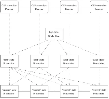
seen by the next state B machines. An example of this structuring is shown in the two rows of B machines at the bottom of Figure1.
CSP is used to model VHDL’s signal update phase. CSP processes determine when all active B operations have completed (i.e., the B operations modelling the active VHDL processes in any given process execution phase). The CSP processes then synchronise to initiate the update of the current state variables with the values held in the next state variables. This requires an additional top-level B machine with write access to the current state B machines, and read access to all of the next state B machines. This structure is shown in Figure1.
3.2 Translating the Traffic Controller
The mapping from user-defined VHDL processes to B operations is straightforward. The op-eration corresponding to the VHDL processfsm is as follows (only one case is shown to save space, but the others are very similar):
fsm=b CASEs.stateOF
EITHERall redTHEN
red maj:=1kyel maj:=0kgrn maj:=0k
red min:=1kyel min:=0kgrn min:=0k
next state:=major ready
ORmajor readyTHEN ..
.
Note, we have prefixed the current state variable state with a unique identifier (s) to distin-guish it from the other (next state) instance of the same variable. The translations of the other VHDL processes follow a similar pattern with one or two subtleties. Consider the VHDL process yellow counter:
yellow counter=b IF (clock event=TRUE∧clock=1 )THEN IF (reset=1 )THEN
yel count:=0 ELSE
IF (yel maj=1∨yel min=1)THEN
yel count:=y.yel count+1 ELSE
yel count:=0 END
END END
Rather than using a bit vector, the variableyel countis declared to be a natural number in the range 0 to 7 in the B model. In order to prove thatyellow counter maintains this typing in-variant, it is necessary to add a precondition to say that the addition can happen only when
y.yel countis less than 7. Otherwise the operation could incrementyel countoutside its range.1 The precondition is generated automatically by taking the conjunction of the conditions that lead to the increment ofyel count.
yellow counter=b
PRE
(clock event=TRUE∧clock=1∧
reset=0∧(yel maj=1∨yel min=1 ) )⇒y.yel count<7 THEN
.. .
It is necessary to add a precondition to the B translation ofgreen counterfor similar reasons but, in this case,grn count’s range is 0 to 127. The two one-line VHDL processes that update ready delayandend delayare translated to (equally succinct) B operations. However, we are obliged to give them names:
set ready delay=b ready delay:=bit(y.yel count, 1 );
set end delay=b end delay:=bit(y.yel count, 2 )
The functionbit(x,y), which returns theyth bit of valuex, is not part of the B language. Hence it is necessary to define it within the B model.
In order to update the current state variables with their next state values, it is necessary to define operations within the current state B machines. These have a uniform structure in which the next state values are passed as input parameters, and the body of the operations are simple assignments of these values to the current state variables. Also, a list of Boolean values are output from the operation to indicate when the values of current state variables have changed. This information can be used to model the sensitivity lists so that the appropriate B operations are called in the next process execution phase. Consider the operationupdate fsm:
dymj,dgmj,dymn,dgmn←− update fsm(rj,yj,gj,rn,yn,gn,ns)=b PRE
rj∈Std Logic∧yj∈Std Logic∧gj∈Std Logic∧
rn∈Std Logic∧yn∈Std Logic∧gn∈Std Logic∧ns∈State
THEN
red maj:=rjkyel maj:=yjkgrn maj:=gjk
red min:=rnkyel min:=ynkgrn min:=gnknext state:=nsk
dymj:=bool(yel maj6=yj)kdgmj:=bool(grn maj6=gj)k
dymn:=bool(yel min6=yn)kdgmn:=bool(grn min6=gn) END
whereStd Logicis a B representation of VHDL’sStd Logictype andStateis the B repre-sentation of the controller state. Note, there are no outputs concerning changes to the red signals because nothing is sensitive to such changes.
The Top-level B machine contains a single B operation called dd which calls all the cur-rent state update operations with the necessary input parameters. It also accumulates all of the Boolean outputs from these individual operations, and uses them as its own output. This sin-gle operation is capable of updating all current state variables simultaneously and provides the necessary information to say which variables have changed. The (abbreviated) definition of the top level B machine is shown below. Note, the operationddcallsupdate fsmwith the actual values of the next state variables inNEXT FSM. (The other operation calls, input parameters, and output parameters are not shown.)
MACHINETop Level
SEESn.NEXT FSM,. . .
INCLUDESCURR FSM,. . .
dymj,dgmj,dymn,dgmn,. . .←−dd=b BEGIN
dymj,dgmj,dymn,dgmn←− update fsm(n.red maj,. . .)k . . .
From Figure1, we see that it is necessary to define CSP processes that control the calling of the various B operations. The idea is to mimic the simulation cycle within the CSP processes. Hence, each controller process begins by calling its associated next state B operation. On com-pletion, the process is ready to call the Top-level B operationdd to update the current state B variables. However, it must wait until all processes are prepared to calldd. When dd occurs, each process can view the outputs from thedd operation to determine which variables’ values have changed and, hence, whether it needs to call its associated next state B operation. If it does not then it waits for the nextddoperation call. Consider the CSP processFSM(other controller processes are similar):
FSM=fsm→FSM0
FSM0 =dd?bb1?...?bbn→if (bbi1or bbi2or · · · or bbim)then FSM else FSM0
3.3 ‘Lifting’ the B Components into CSP
In order to use FDR,liftingis the way important state information is taken from B into CSP. This entails, among other things, parameterising the CSP processes. The effects of the B operations are then modelled as updates to the parameters.
The lifted B operation fsm comprises a choice of guarded processes to represent the case statement(one process for each case):
FSM(st,rdly,gdly,edly,rmj,ymj,gmj,rmn,ymn,gmn,nst) = (st=all red)&
letrmj0=1
ymj0=0
gmj0=0
rmn0=1
ymn0=0
gmn0=0
nst0=major ready
withinFSM0(st,rdly,gdly,edly,rmj0,ymj0,gmj0,rmn0,ymn0,gmn0,nst0)
2(st=major ready)& letymj0=1
nst0=if (rdly=1)then major go else nst
withinFSM0(st,rdly,gdly,edly,rmj,ymj0,gmj,rmn,ymn,gmn,nst0)
2 . . .
ondddiffer from the values held by the process. If so then FSMis called, otherwise control is passed back toFSM0. Note, in the definition ofFSM0below we show the relevant arguments of
ddonly. In this case, the values ofstate,ready delay,grn delayandend delayare relevant because they appear infsm’s sensitivity list.
FSM0(st,rmj,ymj,gmj,rmn,ymn,gmn,nst,rdly,gdly,edly) =
dd. . .?st0. . .?rdly0?gdly0?edly0→
if (st06=st or rdly06=rdly or gdly06=gdly or edly06=edly)then FSM(st0,rdly0,gdly0,edly0,rmj,ymj,gmj,rmn,ymn,gmn,nst)
else FSM0(st,rdly,gdly,edly,rmj,ymj,gmj,rmn,ymn,gmn,nst)
The VHDL process yellow counter is sensitive to changes in the clock signal. Like most processes that are sensitive to the clock signal, the conditional statement within the process checks for a clock edge (in this case a rising edge). Consequently, such conditional statements will never evaluate to true unless they have been preceded by a signal update phase that changed the clock signal. In our formal model, the signal update phase is modelled by the CSP eventdd. Hence, forYELLOW COUNTER(and the formalisation of other clock-sensitive processes) we begin with theddevent.
The definitions of yellow counter and green counterin the B model included precondi-tions that, when evaluated to false, result in unpredictable (divergent) behaviour. It is necessary, therefore, to include these preconditions as diverging assertions in CSP in order to ‘lift’ the B operations completely.
YELLOW COUNTER(yel count) =
dd. . .?yel maj?yel min?. . .
clock event=true∧clock=1∧
reset=0∧(yel maj=1∨yel min=1)
⇒yel count<7
→
if (clock event)then
YELLOW COUNTER0(clock,reset,yel maj,yel min,yel count)
else YELLOW COUNTER(yel count)
YELLOW COUNTER0(clock,reset,yel maj,yel min,yel count) =
let
yel count0=if (clock=1)then if (reset=1)then0
else if (yel maj=1∨yel min=1)then yel count+1
else0
else yel count
within
YELLOW COUNTER(yel count0)
The lifting technique is applied to the other B operations in a similar way.
largely unnecessary because the parallel composition is such that very few of the instances will be exercised during the analysis. Hence, optimisation steps are needed.
3.4 Optimising the CSP for Model Checking
We begin by merging each unprimed/primed process pair into single process definitions. This results in processes with a uniform structure that will make optimisation easier. Consider the lifted CSP processNEW STATE:
NEW STATE(state) =
dd. . .?clock event?clock?reset!state?next state. . .→
if (clock event)then NEW STATE0(clock,reset,state,next state)
else NEW STATE(state)
We can remove the conditional statement by pattern matching onclock event:
NEW STATE(state) =
dd. . .!true?clock?reset!state?next state. . .→NEW STATE0(clock, . . .)
2dd. . .!false?clock?reset!state?next state. . .→NEW STATE(state)
We then incorporate the processNEW STATE0by updating the parameterstatein an appropriate way. This results in an external choice ofddevents:
NEW STATE(state) =
dd. . .!true!1!1!state?next state. . .→NEW STATE(both red)
2dd. . .!true!1!0!state?next state. . .→NEW STATE(next state)
2dd. . .!true!0? !state?next state. . .→NEW STATE(state)
2dd. . .!false? ? !state?next state. . .→NEW STATE(state)
The first dd event handles the case when the clock is 1 and the reset is 1, and results in the
both redstate. The secondddevent handles the case when the clock is 1 and the reset is 0. This replaces the current state with the value bound to thenext stateargument ofdd. The remaining cases keep the current state value.
If we transformYELLOW COUNTERandGREEN COUNTERin a similar manner, we have to somehow incorporate the diverging assertions into the modified process definition. This is done by pattern matching on the processes’ parameters. First recall the lifted definition of
YELLOW COUNTER:
YELLOW COUNTER(yel count) =
dd. . .?yel maj?yel min. . .
clock event=true∧clock=1∧
reset=0∧(yel maj=1∨yel min=1)
⇒yel count<7
→
.. .
YELLOW COUNTER(7) =
dd. . .?yel maj?yel min. . .
clock event=false∨clock=0∨
reset=1∨(yel maj=0∧yel min=0)
→
.. .
Once again, we incorporateYELLOW COUNTER0 to produce a process comprising an external choice of uniqueddevents, but for each case we check whether the diverging assertion is true or false and define the process’s subsequent behaviour accordingly:
YELLOW COUNTER(7) =
dd. . .!true!1!1. . .? ? . . .→ YELLOW COUNTER(0)
2dd. . .!true!1!0. . .!0!0. . . → YELLOW COUNTER(0)
2dd. . .!true!1!0. . .!1!0. . . → DIV
2dd. . .!true!1!0. . .!0!1. . . → DIV
2dd. . .!true!1!0. . .!1!1. . . → DIV
2dd. . .!true!0? . . .? ? . . .→ YELLOW COUNTER(7)
2dd. . .!false? ? . . .? ? . . .→YELLOW COUNTER(7)
The processDIV diverges immediately. Each branch that ends with this process begins with an instance ofddwhose arguments falsify the diverging assertion. There are three cases that cause divergent behaviour, that would otherwise incrementyel countout of bounds. The instance of
YELLOW COUNTERwhen yel countis not 7 is identical except the calls toDIV are replaced by calls toYELLOW COUNTER(yel count+1) (i.e., there is no divergent behaviour). There are corresponding definitions forGREEN COUNTER.
The (abbreviated) definition ofFSMshown below is the result of incorporatingFSM0into the ‘lifted’ definition of FSM. By pattern matching on the current state argument ofdd we once again get a process that is an external choice of unique instances ofdd, each of which is followed by a conditional statement to determine the next course of action. Note that each branch has the same structure as the body ofFSM0.
FSM(st,rmj,ymj,gmj,rmn,ymn,gmn,ns,rdly,gdly,edly) =
dd. . .!both red!rmj!ymj!gmj!rmn!ymn!gmn!ns?rdly0?gdly0?edly0→
(if (st6=both red∨rdly6=rdly0∨gdly6=gdly0∨edly6=edly0)then FSM(both red,1,0,0,1,0,0,major ready,rdly0,gdly0,edly0)
else FSM(st,rmj,ymj,gmj,rmn,ymn,gmn,ns,rdly,gdly,edly))
2dd. . .!major ready!rmj!ymj!gmj!rmn!ymn!gmn!ns!0?gdly0?edly0→
(if (st6=major ready∨rdly6=0∨gdly6=gdly0∨edly6=edly0)then FSM(major ready,rmj,1,gmj,rmn,ymn,gmn,ns,0,gdly0,edly0)
else FSM(st,rmj,ymj,gmj,rmn,ymn,gmn,ns,rdly,gdly,edly))
2. . .
The delay processes (not shown) are transformed in a similar manner.
We illustrate this by merging the NEW STATE process with the counter processes and delay processes because, individually, these process contribute one argument each todd; collectively, they contribute six arguments. When merging processes, the divergent processDIVtakes prece-dence: if any single process diverges in a given state then the entire process diverges. Merging preserves the structure of the processes derived in the previous step (i.e., an external choice of
ddevents), so merging can be repeated as often as necessary. In this instance, we shall call the resulting processNS YC GC DLY. In its most general form, the merged process is:
NS YC GC DLY(0,st,yc,gc,rdly,gdly,edly) =
dd!true!1!1!st? ? ? ? ? ? ? !rdly!gdly!edly→
NS YC GC DLY(1,both red,0,0,bit(yc,1),bit(gc,6),bit(yc,2))
2dd!true!1!0!st? !1!1? ? ? ?ns!rdly!gdly!edly→
NS YC GC DLY(1,ns,yc+1,gc+1,bit(yc,1),bit(gc,6),bit(yc,2))
2dd!true!1!0!st? !0!1? !0? ?ns!rdly!gdly!edly→
NS YC GC DLY(1,ns,0,gc+1,bit(yc,1),bit(gc,6),bit(yc,2))
2dd!true!1!0!st? !1!0? ? !0?ns!rdly!gdly!edly→
NS YC GC DLY(1,ns,yc+1,0,bit(yc,1),bit(gc,6),bit(yc,2))
2. . .
Note that, due to the merging of the counter processes and the delay processes, the count param-eters (ycandgc) are no longer needed outside this process. Hence, they are removed from the arguments ofdd. There are three other (pattern matching) instances of this process that exhibit some divergent behaviour.
4
Model Checking
Our controller can now defined as:
CONTROLLER = FSM(both red,1,0,0,1,0,0,major ready,0,0,0)
|[{|dd|}]|NS YC GC DLY(0,both red,0,0,0,0,0)
The values of the parameters are the same values that would have been assigned by the next state B operations. Hence, the initial state ofCONTROLLER corresponds to the VHDL prior to its first signal update phase.
We renameCONTROLLERso that we can use FDR to check that it refinesSPEC RR. For ex-ample,dd!true!1!0!both red!1!0!0!1!0!0!major ready? is renamed asboth red to maj red yel. IfREN is the entire renaming then by hiding the remainingddevents we can perform a refine-ment check in FDR:
assert SPEC RRvTCONTROLLER[[REN]]\ {|dd|}
that we are not hiding any events, so if the check fails then it is by virtue of aDIVprocess. The livelock-free check succeeds, and we conclude that the controller does not attempt to increment one of its counters out of bounds.
5
Conclusion
The challenge that prompted this work was to combine formal and informal approaches to pro-duce verified hardware. The proposed solution allows the hardware developers to continue to use their informal approaches, but complements this with a method for translating VHDL to formal notations for analysis. Of all the related work, perhaps the most relevant is [ZT05] (in combina-tion with [BGR00]) which translates B specifications and existing VHDL to ACL2 for analysis. However, in our case, the project requirements influenced the choice of formal approach con-siderably. CSP was used because it is a good language to formalise requirements of this form. The B Method was less suitable in this respect because, at its most abstract level, control flow is implicit.
The language of the B Method is, however, very similar to VHDL, and translating from VHDL to B is quite straightforward. CSP can also be used to provide the necessary control, which motivates a CSPkB approach. The ProB [LB03] tool is available to do trace refinement checks, but other kinds of checks (such as those described in Section4) are not available. The approach presented here uses the existing CSPkB techniques to ‘lift’ the B components into CSP in order to use FDR. Another piece of work using CSP in a VHDL context is [CH97], but this focuses on synthesis.
The problem with using FDR lies in its eager approach to building transition graphs. An opti-misation technique has been proposed in this paper to circumvent this problem. In this respect, ProB would be better because it uses a lazy approach. Scalability is always a key issue with for-mal methods. The optimisation can be repeated as necessary, so it works for larger specifications with more processes. Automation of the approach is ongoing work.
A lot of work has been done on the formal semantics of VHDL (including [FM95]). This work provides useful insights into VHDL itself, but cannot be deployed in an industrial context directly.
Acknowledgements: The author is very grateful to the anonymous referees and workshop participants for their useful comments.
Bibliography
[Abr96] J. R. Abrial.The B Book: Assigning Programs to Meaning. CUP, 1996.
[CH97] R. Chapman, D. H. Hwang. A Formally Verified High-Level Synthesis Front-end: Translation of VHDL to Dependence Flow Graphs. InEuroDAC ’97. ACM, 1997.
[FM95] M. Fuchs, M. Mendler. A Functional Semantics for Delta-Delay VHDL Based on Focus. In Kloos and Breuer (eds.), Formal Semantics for VHDL. Kluwer Academic Publishers, 1995.
[For] Formal Systems (Europe) Ltd. Failures-Divergences Refinement: FDR2 Manual.
[Hoa85] C. A. R. Hoare.Communicating Sequential Processes. Prentice Hall, 1985.
[IEE02] IEEE Comp. Society. IEEE Standards: VHDL Language Reference Manual. 2002.
[LB03] M. Leuschel, M. Butler. ProB: A Model Checker for B. In Araki et al. (eds.),
FM’2003: Formal Methods. LNCS 2805. Springer, 2003.
[Sch99] S. Schneider.Concurrent and Real-Time Systems: the CSP Approach. Wiley, 1999.
[ST02] S. Schneider, H. Treharne. Communicating B machines. In ZB2002. LNCS 2272. Springer, 2002.
[ST05] S. Schneider, H. Treharne. CSP Theorems for Communicating B Machines.Formal Aspects of Computing17:390–422, 2005.