Avaya Solution & Interoperability Test Lab
Application Notes for VoIP over PPP and MLPPP Links
using a Foundry Networks AccessIron AR1204 Access
Router, an Avaya G350 Media Gateway with an MM340
WAN Media Module, and an Avaya IP Office - Issue 1.0
Abstract
These Application Notes describe a configuration for supporting Voice over IP (VoIP) over Point-to-Point Protocol (PPP) and Multilink PPP (MLPPP) links with Quality of Service (QoS) on a Foundry Networks AccessIron AR1204 Access Router, an Avaya G350 Media Gateway with an MM340 WAN Media Module, and an Avaya IP Office. QoS, based on Layer 3 Differentiated Services, was implemented across the network to prioritize voice traffic over the WAN. Emphasis was placed on verifying good voice quality in a converged network. Information in these Application Notes has been obtained through compliance testing and additional technical discussions. Testing was conducted via the DeveloperConnection Program at the Avaya Solution and Interoperability Test Lab.
1. Introduction
These Application Notes describe a configuration for supporting Voice over IP (VoIP) over PPP and MLPPP links with Quality of Service (QoS) on a Foundry Networks AccessIron AR1204 Access Router, an Avaya MM340 WAN Media Module installed in an Avaya G350 Media Gateway, and an Avaya IP Office. The WAN was used to exchange voice and data traffic between three sites. To achieve good voice quality across the WAN, QoS based on Layer 3 Differentiated Services (DiffServ) was configured on the WAN interfaces of the Avaya G350 Media Gateway, Avaya IP Office and the Foundry Networks AccessIron AR1204. Before the Avaya and Foundry Networks access routers can enforce QoS, they must be able to distinguish between low and high priority traffic. This required that the Avaya Media Servers and Gateways, and the Avaya IP Telephones mark voice signaling and media packets with a Differentiated Service Code Point (DSCP) value so that the WAN access routers can identify the high priority VoIP packets and prioritize them accordingly.
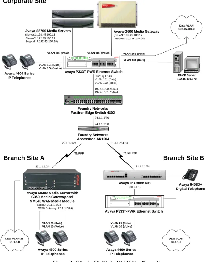
The site-to-multisite configuration shown in Figure 1 illustrates a corporate site connected to two branch office sites over the WAN using PPP and MLPPP links. Each site consists of an Avaya Media Server and Gateway and Avaya IP telephones. The network devices at the corporate site and site B were interconnected via an Avaya P333T Stackable Ethernet Switch and the end-user devices at site A were connected to a Power-over-Ethernet switch (MM314) installed in the G350 Media Gateway. At the corporate site, a FastIron Edge Switch (FES) 4802 was used as a Layer 3 switch for routing within the enterprise. At the branch office sites, the internal routers in the G350 Media Gateway and the IP Office were used to route packets between the voice and data VLANs as well as to the corporate site.
Avaya G600 Media Gateway
(C-LAN: 192.45.100.17 MedPro: 192.45.100.20)
Avaya S8700 Media Servers
(Server1: 192.45.100.11 Server2: 192.45.100.12 Logical IP:192.45.100.10)
Avaya P333T-PWR Ethernet Switch
T1/MLPPP
Corporate Site
Branch Site A
VLAN 100 (Voice) VLAN 100 (Voice)
VLAN 101 (Data) 802.1Q Trunk VLAN 101 (Data) VLAN 100 (Voice) 192.45.100.254/24 192.45.101.254/24 T1/PPP VLAN 101 (Data) VLAN 101 (Data) VLAN 100 (Voice)
FastIron Edge 4802-POE 4 9 F 5 0 F FOUNDRY N E T W O R K S C o n s o le 4 9 C 5 0 C L n k A c t P S 1 P S 2 P o w e r L n k /A c tF D X P o w e r1 2 3 4 5 6 7 8 9 10 11 12 123 456789101112 13 14 15 16 17 18 19 20 21 22 23 24 13141516171819 2021 222324 25 26 27 28 29 30 31 32 33 34 35 36 25262728293031 3233343536 37 38 39 40 41 42 43 44 45 46 47 48 37383940414243 4445 464748 WA N S T A T U S E T H E R N E T 0 LIN K /A C T H SD U P E T H E R N E T 1 LIN K /A C T H SD U P AccessIr on AR1204 FOUNDRY N E T WO R K S 4 3 2 1 Foundry Networks AccessIron AR1204 Foundry Networks FastIron Edge Switch 4802
VLAN 21 (Data) VLAN 20 (Voice) Avaya IP Office 403 (30.1.1.1) DHCP Server 192.45.101.170 Data VLAN 192.45.101.0
Avaya P333T-PWR Ethernet Switch
Avaya 4600 Series IP Telephones Data VLAN 21 21.1.1.0 VLAN 21 (Data) VLAN 20 (Voice) Avaya 4600 Series IP Telephones Avaya 4600 Series IP Telephones
Branch Site B
Avaya 6408D+ Digital Telephone Data VLAN 31.1.1.0 24.1.1.1/30 24.1.1.2/30 22.1.1.2/24 31.1.1.254/24 31.1.1.1/24 22.1.1.1/24Avaya S8300 Media Server with
(S8300: 20.1.1.1/24 G350 Gateway: 20.1.1.2/24)
G350 Media Gateway and MM340 WAN Media Module
2. Equipment and Software Validated
The following equipment and software were used for the sample configurations provided:
Equipment Software
Avaya S8700 Media Server with Avaya G600 Media Gateway
Avaya Communication Manager 2.1
(R012x.01.0.411.7)
Avaya TN799DP C-LAN HW01 FW012
Avaya TN2302AP IP Media Processor HW03 FW093 Avaya S8300 Media Server with Avaya G350 Media
Gateway
Communication Manager 2.1.1 (R012x.01.1.414.1)
Avaya MM340 WAN Media Module HW53 FW000
Avaya IP Office 2.1(15)
Avaya P333T-PWR Stackable Switch 3.12.1
Avaya 4600 Series IP Telephone 2.1
Avaya 6408D Digital Phones --
Foundry Networks AccessIron AR1204 WAN Access Router
8.0.1 Foundry Networks FastIron Edge Switch 4802 in Layer
3 Mode
3.2.0a
3. Configure the Avaya Media Servers
These Application Notes describe a QoS solution based on DSCP markings to classify traffic in the network for QoS handling. This requires that the Avaya Media Servers and Gateways as well as the Avaya IP Telephones mark outgoing VoIP media and signaling packets with DSCP values. For the configuration described herein, VoIP media and signaling packets were tagged with DSCP values 46 and 34, respectively. VoIP media packets are sent by the VoIP resource in the G350 Media Gateway, the IP Media Processor in the G600 Media Gateway, and the Avaya IP Telephones. VoIP signaling packets are sent by the S8300 Media Server, the C-LAN in the G600 Media Gateway, and the Avaya IP Telephones. All of these components derive the DSCP values from the IP network region to which they belong. The C-LAN and IP Media Processor are assigned to the IP Network Region specified in the IP Interface form, and the G350 Media Gateway is assigned to the IP network region specified in the Media Gateway form. The IP network region for the IP telephones is either specified in the IP Network Map form or inherited from their C-LAN or S8300 Processor. The IP telephones acquire the appropriate DSCP values during H.323 registration with their respective media server.
IP network region ‘2’ and IP codec set ‘1’ were used on the Avaya Media Servers at the corporate site and site A. The ip-network-region, ip-codec-set, and ip-network-map forms are configured the same way for each media server. The configuration shown below is associated with the S8700 Media Server and G600 Media Gateway, but may be applied to the S8300 Media Servers and G350 Media Gateway, except where specified. Note that the H.323 signaling group,
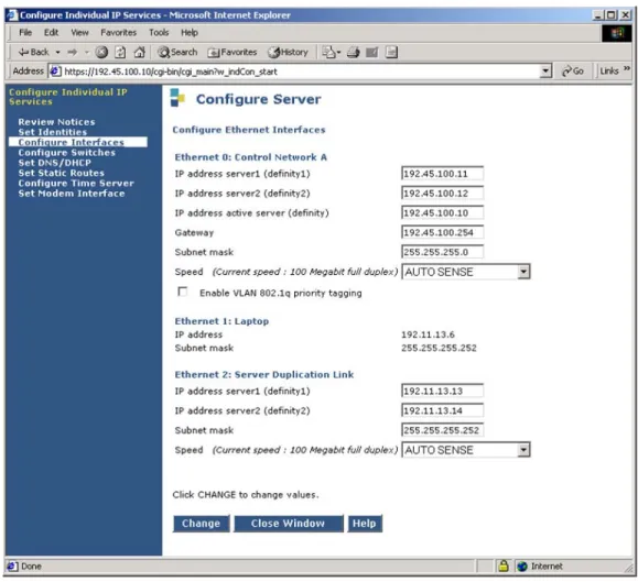
The Avaya S8700 Media Server is configured using a web interface. Enter the media server’s IP address as the URL in a web browser to access the web interface. Follow the prompts and then log in. Select the configure server option, to access the server configuration page and set the IP address and default gateway of the S8700 Media Server. The default gateway of the S8700 Media Server is the FES 4802 at the Corporate Site. The Gateway field should be set to the IP address of the FES 4802 corresponding to the voice VLAN (i.e., VLAN ID 100 and IP address 192.45.100.254) since the media server belongs to the voice VLAN in this configuration. This ensures that the S8700 Media Server is accessible throughout the network for system management purposes only. VoIP media and H.323 signaling traffic flows to/from the IP Media Processor, C-LAN, and IP telephones at the corporate site, not the S8700 Media Server. Repeat this configuration for the S8300 Media Server using the appropriate IP configuration.
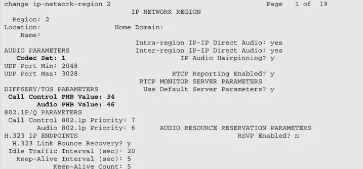
From the System Access Terminal (SAT), enter the change ip-network-region 2 command to configure the DiffServ values for the C-LAN and IP Media Processor. IP network region ‘2’ is assigned to the C-LAN and IP Media Processor in the ip-interfaces forms shown in Figures 6
and 7. The IP telephones are programmed with these DiffServ values automatically when they register via the C-LAN. The default settings of the ip-network-region form were used. Repeat this configuration on the S8300 Media Server.
change ip-network-region 2 Page 1 of 19 IP NETWORK REGION
Region: 2
Location: Home Domain: Name:
Intra-region IP-IP Direct Audio: yes AUDIO PARAMETERS Inter-region IP-IP Direct Audio: yes Codec Set: 1 IP Audio Hairpinning? y UDP Port Min: 2048
UDP Port Max: 3028 RTCP Reporting Enabled? y RTCP MONITOR SERVER PARAMETERS DIFFSERV/TOS PARAMETERS Use Default Server Parameters? y
Call Control PHB Value: 34
Audio PHB Value: 46
802.1P/Q PARAMETERS
Call Control 802.1p Priority: 7
Audio 802.1p Priority: 6 AUDIO RESOURCE RESERVATION PARAMETERS H.323 IP ENDPOINTS RSVP Enabled? n H.323 Link Bounce Recovery? y
Idle Traffic Interval (sec): 20 Keep-Alive Interval (sec): 5 Keep-Alive Count: 5
Figure 3: IP Network Region Form
On the ip-codec-set form, select the audio codec type to be used by the media processors and IP telephones in IP network region ‘2’. Note that IP codec set ‘1’ was specified in IP network region ‘2’ in Figure 3. The form is accessed via the change ip-codec-set 1 command. The default settings of the ip-codec-set form are shown below. However, the Audio Codec field may be set to G.729 to conserve bandwidth on the WAN interface. Repeat this configuration on the S8300 Media Server.
change ip-codec-set 1 Page 1 of 1 IP Codec Set
Codec Set: 1
Audio Silence Frames Packet Codec Suppression Per Pkt Size(ms) 1: G.711MU n 2 20 2: 3: 4: 5: 6:
On the ip-network-map form, assign IP network region ‘2’ to the Avaya IP Telephones whose IP addresses are in the specified IP address range. The IP telephones inherit the IP network region of the C-LAN or S8300 Processor if the ip-network-map form is not used.
change ip-network-map Page 1 of 32 IP ADDRESS MAPPING
Emergency Subnet Location From IP Address (To IP Address or Mask) Region VLAN Extension
192.45 .100.0 192.45 .100.255 24 2 100
. . . . . . n . . . . . . n
Figure 5: IP Network Map
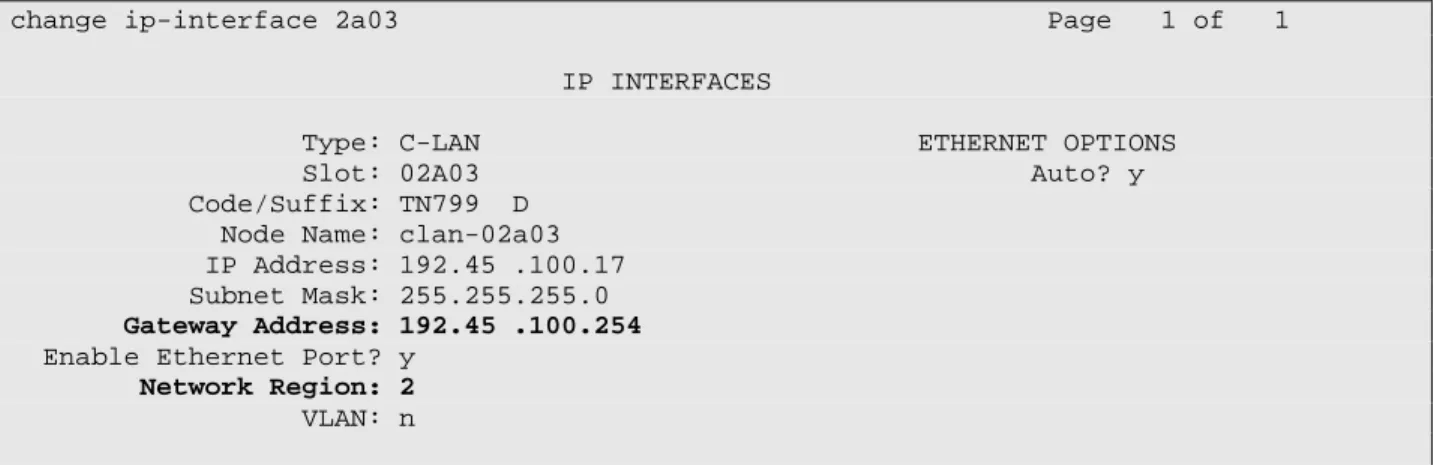
Assign a default gateway and IP network region to the C-LAN via the change ip-interface 2a03
form. The default gateway is the FES 4802 (192.45.100.254) at the corporate site. The C-LAN was assigned to IP network region ‘2’. The C-LAN accepts registration and call setup requests from the IP telephones, and exchanges call setup messages with the Avaya Media Servers at the other sites to establish VoIP calls. There is an H.323 trunk group and signaling group configured between the Avaya Media Servers not described in these Application Notes.
change ip-interface 2a03 Page 1 of 1 IP INTERFACES
Type: C-LAN ETHERNET OPTIONS Slot: 02A03 Auto? y Code/Suffix: TN799 D
Node Name: clan-02a03 IP Address: 192.45 .100.17 Subnet Mask: 255.255.255.0
Gateway Address: 192.45 .100.254
Enable Ethernet Port? y
Network Region: 2
VLAN: n
Number of CLAN Sockets Before Warning: 400
Lastly, assign a default gateway and IP network region to the IP Media Processor via the change ip-interface 2a04 form. The default gateway is the FES 4802 (192.45.100.254) at the corporate site. The IP Media Processor was assigned to IP network region ‘2’.
change ip-interface 2a04 Page 1 of 1 IP INTERFACES
Type: MEDPRO ETHERNET OPTIONS Slot: 02A04 Auto? y Code/Suffix: TN2302
Node Name: medpro-02a04 IP Address: 192.45 .100.20 Subnet Mask: 255.255.255.0
Gateway Address: 192.45 .100.254
Enable Ethernet Port? y
Network Region: 2
VLAN: n
Figure 7: Avaya S8700 Media Server – IP Interfaces Form (IP Media Processor) Figure 8 shows the configuration of the Avaya G350 Media Gateway and applies to site A only. When adding the G350 Media Gateway, set the Type field to g350, specify the serial number of the media gateway in the Serial No field, and assign the appropriate network region. The following screen displays the media-gateway form after it was added and the gateway has registered.
change media-gateway 1 Page 1 of 1 MEDIA GATEWAY
Number: 1 IP Address: 20 .1 .1 .254
Type: g350 FW Version/HW Vintage: 22 .16 .0 /1
Name: G350 Media Gateway MAC Address: 00:04:0d:29:d2:c5
Serial No: 03IS69612698 Encrypt Link? y
Network Region: 2 Location: 1
Registered? y Controller IP Address: 20 .1 .1 .1 Site Data:
Slot Module Type Name V1: S8300 ICC MM V2: MM340 DS1 WAN MM V3: MM712 DCP MM V4: V5: MM710 DS1 MM V6: MM314 ETH 24P MM V7: virtual-analog ANA VMM V8: V9:
4. Configure the Avaya G350 Media Gateway
This section describes the steps for configuring the G350 Media Gateway, including the MM340 WAN Media Module. The WAN media module provides WAN connectivity for the G350 Media Gateway and the IP telephones located at Branch Site A. The WAN Media Module is configured for PPP encapsulation with DiffServ-based QoS. For a description of the QoS implementation of the MM340 WAN Media Module see reference [3].
Step Description
1 Connect a PC or laptop to the G350 Media Gateway via the console port and use a terminal emulation program to configure the system using the CLI interface. Log in to the G350 Media Gateway using the appropriate credentials.
Note: The 001 in the command prompt shown below refers to the G350 Media Gateway number configured on the media server via the add media-gateway command. It is displayed in the command prompt when the G350 Media Gateway has successfully registered with the S8300 Media Server. Prior to registration, ??? is displayed instead of the media gateway number.
2 Create two VLANs on the G350 Media Gateway, one for voice and the other for data. Assign the voice and data VLANs to Ethernet ports 6/1 and 6/2, which are connected to IP telephones. VLAN 21 is assigned to Ethernet port 6/7 and 6/8 which are connected to data devices, such as PCs.
G350-001# set vlan 20 name SiteA-Voice
G350-001# set vlan 21 name SiteA-Data
G350-001# set port vlan 21 6/1-2
G350-001# set port vlan 21 6/7-8
G350-001# set port static-vlan 6/1-2 20
3 Configure the interface associated with voice VLAN 20 on the G350 Media Gateway. Specify the IP address of the G350 Media Gateway, configure the ICC (i.e., S8300 Media Server) on the voice VLAN, designate the voice VLAN interface as the Primary Management Interface (PMI), and specify the IP address of the DHCP server. The PMI interface is the one that is used to register with the S8300 Media Server. In this configuration, the DHCP server is at the corporate site. Use the show ip interfaces
command to check the status of the interface.
G350-001# interface Vlan 20
G350-001(if:Vlan 20)# ip address 20.1.1.254 255.255.255.0
G350-001(if:Vlan 20)# icc-vlan
G350-001(if:Vlan 20)# pmi
G350-001(if:Vlan 20)# ip bootp-dhcp server 192.45.101.170
Step Description
4 Configure the interface associated with data VLAN 21 on the G350 Media Gateway. Specify the IP address for the data VLAN interface on the G350 Media Gateway and specify the IP address of the DHCP server. Use the show ip interfaces command to check the status of the interface.
G350-001# interface Vlan 21
G350-001(if:Vlan 21)# ip address 21.1.1.254 255.255.255.0
G350-001(if:Vlan 21)# ip bootp-dhcp server 192.45.101.170
G350-001(if:Vlan 21)# exit
5 Enable the DHCP relay agent function on the G350 Media Gateway to allow DHCP broadcast requests from one VLAN to be sent to the DHCP server on a different VLAN or network.
G350-001# ip bootp-dhcp relay
6 Configure the G350 controller IP address using the set mgc list command. The Media Gateway Controller (MGC) is set to the IP address of the S8300 Media Server.
G350-001# set mgc list 20.1.1.1
7 Set the mode of the WAN media module to T1 or E1. By default, the controller is set to T1.
G350-001# ds-mode t1
8 By default, the G350 Media Gateway is pre-configured with a QoS list that prioritizes VoIP traffic marked with DSCP values 34 and 46. The pre-configured QoS list is 400. The show ip active-lists command can be used to view the QoS lists applied to the interfaces on the G350. Therefore, no further configuration is required to enable QoS. However, a user may choose to override the default QoS list. For illustrative purposes, an example is shown below where a new QoS list is defined. The example below creates QoS list 401 that matches signaling packets with DSCP value 34 and assigns it Class of Service (CoS) priority 7, and matches media packets with DSCP value 46 and assigns it CoS 6. Finally, this example applies maximum trust to 802.1p priority and DSCP. Note that this QoS list was not applied to any interfaces and is only being shown as an example.
G350-001# ip qos-list 401
G350-001(QoS 401)# dscp-table 34
G350-001(QoS 401/dscp 34)# composite-operation CoS7
G350-001(QoS 401/dscp 34)# exit
G350-001(QoS 401)# dscp-table 46
G350-001(QoS 401/dscp 46)# composite-operation CoS6
G350-001(QoS 401/dscp 46)# exit
G350-001(QoS 401)# pre-classification trust-cos-dscp
Step Description
9 Link fragmentation and interleaving (LFI) is enabled on the G350 by default. LFI allows the G350 to fragment large packets on PPP links to reduce the serialization delay of large packets being transmitted over low-speed WAN links. The maximum number of fragments per packet is configured using the fragment chain command. By default, it is set to 64. No additional configuration is required to enable LFI. Use the show fragment command to display fragmented IP packets information.
10 Configure the T1 controller with a linecode of b8zs, framing of esf, and to derive timing from the network. Create a channel group and specify the timeslots to map to it. In this example, all 24 channels of the T1 interface are mapped to channel group ‘1’ with a DS0 speed of 64kbps.
G350-001# controller t1 2/1
G350-001(controller:2/1)# linecode b8zs
G350-001(controller:2/1)# framing esf
G350-001(controller:2/1)# clock source line
G350-001(controller:2/1)# channel-group 1 timeslots 1-24 speed 64
G350-001(controller:2/1)# exit
11 Configure the serial interface. In this example, serial interface 2/1:1 refers to the media module in slot 2, port number 1, and channel group 1. Configure the serial interface for PPP encapsulation and assign an IP address to the interface. Set the bandwidth of the serial interface to 1.536Mbps and enable VoIP mode to select custom queuing and queue sizes for VoIP traffic.
G350-001# interface serial 2/1:1
G350-001(if:Serial 2/1:1)# description "PPP Link to Corporate Site"
G350-001(if:Serial 2/1:1)# encapsulation ppp
G350-001(if:Serial 2/1:1)# ip address 22.1.1.1 255.255.255.0
G350-001(if:Serial 2/1:1)# bandwidth 1536
G350-001(if:Serial 2/1:1)# voip-queue
G350-001(if:Serial 2/1:1)# exit
12 Define a default gateway for the G350 Media Gateway for connecting to the corporate site.
G350-001# ip default-gateway 22.1.1.2
13 Use the copy command to save changes to the startup configuration of the G350 Media Gateway.
5. Configure the Avaya IP Office
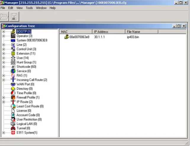
This section describes the steps required to configure the IP Office with DSCP values for VoIP traffic, IP trunks to the corporate site, shortcodes for routing VoIP calls, and an MLPPP link over a T1 interface. The IP Office was configured using the Avaya IP Office Manager application. To configure the Avaya IP Office, open the Manager application from a PC connected to the IP Office via IP. Initially, the IP Office is assigned IP address 192.168.42.1 with a subnet mask of 255.255.255.0. The Manager main window in Figure 9 is displayed. All of the configuration options are selected from the tree view of the Manager window.
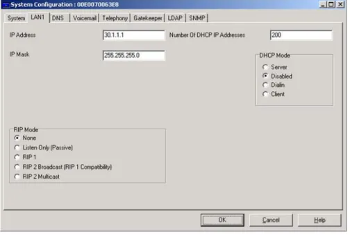
To configure an IP address on the IP Office, select the System option. In the LAN1 tab, set the
IP Address and IP Mask as shown in Figure 10. At a customer site, specify the IP configuration that corresponds to the customer’s network.
Figure 10: System Configuration – LAN1 Tab
In the Gatekeeper tab, verify that the DSCP values for VoIP media and signaling traffic are set to 46 and 34, respectively, as depicted in Figure 11. The Avaya IP Telephones that register with the IP Office will inherit these DSCP values during H.323 registration. These are the DSCP values used in the configuration described in these Application Notes.
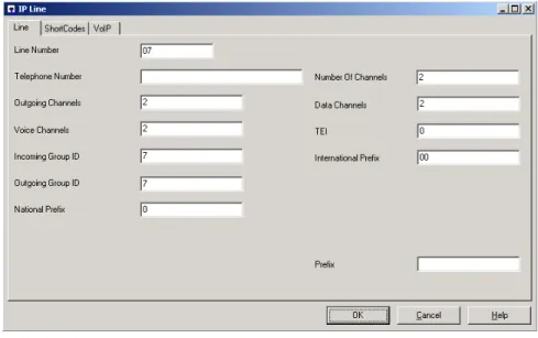
Next, create an IP trunk to the Avaya Media Server and Gateway at the corporate site. Select the
Line option from the Manager tree view and add an IP Line. Specify the Line Number, the number of Outgoing Channels and Voice Channels in this IP line, and the Incoming and
Outgoing Group ID. The Outgoing Group ID is specified in the shortcode that routes outgoing calls to the corporate site. Figure 12 displays the IP Line configuration used for the sample configuration.
Figure 12: IP Line – Line Tab
Under the VoIP tab of the IP Line form, set the Gateway IP Address to the IP address of the C-LAN in the G600 Media Gateway at the corporate site. The Compression Mode was set to
Automatic Selection so that the codec type used for the call would be negotiated during call setup. The Allow Direct Media Path feature was disabled in the sample configuration. This configuration corresponds to the H.323 signaling group on the S8700 Media Server (not shown).
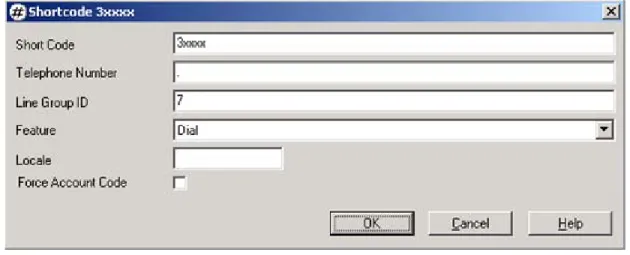
To route calls to IP telephones at the corporate site, create a shortcode by selecting the
Shortcode option from the Manager tree view shown in Figure 9. The extensions at the corporate site begin with the digit ‘3’ and are 5-digits in length. In this example, the shortcode specifies that calls with dialed digits in the format 3xxxx, where ‘x’ denotes a wildcard, are routed over Line Group ID ‘7’ which was configured in Figure 12. The Telephone Number
field was set to ‘.’ which means that all of the dialed digits are sent over the IP trunk.
Figure 14: Shortcode
Add IP Extensions and Users for the IP telephones that will register with the IP Office. The reader should consult the Avaya IP Office documentation listed in Section 13 for instructions on adding IP stations.
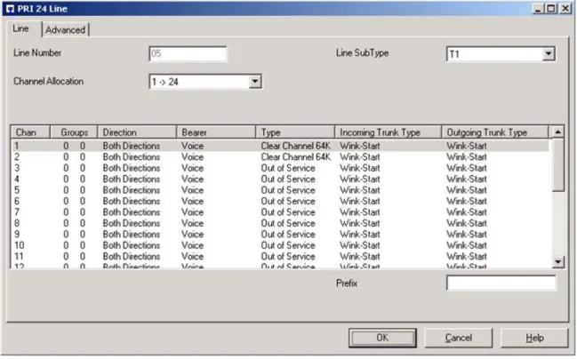
To configure the MLPPP link over a T1 connection, the following screens should be configured as described. Begin by configuring the T1 interface for the WAN link. Select the Link option on the Manager tree view and then right mouse click on the right pane to display the pop-up menu. The PRI 24 Line screen is displayed in Figure 15. In this example, the WAN link was configured with a bandwidth of 128kbps (i.e., two T1 channels). To configure each channel, highlight a channel or group of channels and right mouse click to display the pop-up menu. From the menu, select the edit option. The screen in Figure 16 is displayed.
Note: Avaya IP Office 403 supports up to 10 data channels for its WAN link, which provides a maximum bandwidth of 640 kbps. Avaya IP Office 406 and 412 support up to 20 and 30 data channels, respectively. Exceeding the maximum data channels per platform will prevent the WAN link from being established successfully.
Figure 15: PRI 24 Line – Line Tab
Configure each T1 channel as shown in the Figure 16 and then click OK.
The default T1 settings on the Advanced tab are appropriate for this configuration. No modifications are required.
Figure 17: PRI 24 Line – Advanced Tab
Configure the WAN link by selecting the Service option on the Manager tree view and then right mouse click on the right pane to display the pop-up menu. From the menu, select New. The WAN Service window in Figure 18 is displayed. In the Service tab, specify a name for the WAN link.
In the IP tab, specify an IP address and mask for the WAN interface.
Figure 19: WAN Service – IP Tab
Configure the PPP tab as shown in Figure 20. Enable MultiLink / QoS and disable the
Compression Mode and Callback Mode. Note that IPHC Header Compression Mode is disabled. Click OK.
Next, select the WAN Port option in the Manager tree view and right mouse click on the right pane to display the pop-up menu. From the menu, select New. The WAN Port window is displayed as shown in Figure 21. For this configuration, set the Speed to 128000, the Mode to
SyncPPP, and the RAS Name to wan_link. Click OK.
Figure 21: WAN Port
Finally, select the IP Route option from the Manager tree view to configure a default route
Figure 22: IP Route
6. Configure the Foundry Networks FastIron Edge Switch
4802
This section provides the configuration for the FastIron Edge Switch 4802 in the corporate site.
Step Description
1 The followings commands access the configuration level and set the system name.
4802> en
4802# config t
4802(config)# hostname CorpCore
2 Create two VLANs on the FES 4802. VLAN 100 is associated with the voice VLAN and VLAN 101 is associated with the data VLAN. The following configuration assigns VLANs 100 and 101 to port 1, which connects to the Avaya P333T, and enables 802.1q tagging. In addition, a router interface is added to allow routing between the VLANs. Configure port-based VLAN 100, add virtual interface 100 as the routing interface for the VLAN, and enable 802.1q tagging on Ethernet port 1.
CorpCore(config)# vlan 100 by port
CorpCore(config-vlan-100)# tagged ethernet 1 CorpCore(config-vlan-100)# router-interface ve 100
CorpCore(config-vlan-100)# exit
Configure port-based VLAN 101, add virtual interface 101 as the routing interface for the VLAN, and enable 802.1q tagging on Ethernet port 1.
CorpCore(config)# vlan 101 by port
CorpCore(config-vlan-101)# tagged ethernet 1 CorpCore(config-vlan-101)# router-interface ve 101
CorpCore(config-vlan-101)# exit
3 Create access-list 101 that marks packets from the C-LAN in the G600 Media Gateway (192.45.100.17) with DSCP value 34. The C-LAN in the G600 Media Gateway sends keep-alive messages to the far-end media server to maintain the IP trunk in-service. The following access list is required so that the keep-alive messages are marked with a DSCP value and prioritized downstream by the AR1204. This will allow the keep-alive messages to arrive at the other end in spite of competing low priority traffic in the network. The access list is applied to an interface in Step 4.
CorpCore(config)# access-list 101 permit ip host 192.45.100.17 any
tos-marking 34
Step Description
4 Configure virtual interface 100 and 101. Assign access list 101 to interface 100 in the incoming direction since that is the interface on the same network as the C-LAN card. Packets received by the C-LAN card will be marked with DSCP 34 and prioritized by the AR1204. Furthermore, assign an IP address to each interface.
CorpCore(config)# interface ve 100 CorpCore(config-vif-100)# ip access-group 101 in CorpCore(config-vif-100)# ip address 192.45.100.254 255.255.255.0 CorpCore(config-vif-101)# ip helper-address 1 192.45.101.170 CorpCore(config-vif-100)# exit CorpCore(config)# interface ve 101 CorpCore(config-vif-101)# ip address 192.45.101.254 255.255.255.0 CorpCore(config)# exit
5 Configure a default static route for routing traffic to the AR1204.
CorpCore(config)# ip route 0.0.0.0 0.0.0.0 24.1.1.2
6 Configure OSPF routing between the FES 4802 and the AR1204.
CorpCore(config)# router ospf
CorpCore(config-ospf-router)# area 0
CorpCore(config-ospf-router)# redistribution connected CorpCore(config-ospf-router)# exit
7 Configure Ethernet port 2, which connects to the AR1204. Assign an IP address and subnet mask to the interface and enable OSPF routing.
CorpCore(config)# interface ethernet 2
CorpCore(config-if-e100-2)# ip address 24.1.1.1 255.255.255.252
CorpCore(config-if-e100-2)# ip ospf area 0
CorpCore(config-if-e100-2)# exit
8 Use the following command to save the configuration.
7. Configure the Foundry Networks AccessIron AR1204
The AccessIron AR1204 provides WAN connectivity for the corporate site using PPP and MLPPP links. The AR1204 supports four T1 interfaces. The first T1 interface on the AR1204 is configured as a PPP link to site A and the third T1 interface is configured as an MLPPP link to site B.
Step Description
1 The following commands access the configuration level and set the system name. AR1204# config t
2 Configure the Ethernet interface connected to the FES 4802. AR1204/configure# interface ethernet 0
AR1204/configure/interface/ethernet 0# ip address 24.1.1.2 255.255.255.252
AR1204/configure/interface/ethernet 0# exit
3 Configure the T1 interfaces. By default, the T1 interfaces on the AR1204 are configured with framing set to esf, linecode set to b8zs, and clock source set to internal. The default settings are appropriate for the configuration described herein. No additional configuration is required for the physical T1 interfaces.
4 The PPP link between the AR1204 and the MM340 WAN Media Module in the G350 Media gateway is configured under interface bundle wan1. In this example, the WAN interface is configured as PPP with a bandwidth of 1.536Mbps. An IP address is also assigned to the interface.
AR1204/configure# interface bundle wan1
AR1204/configure/interface/bundle wan1# link t1 1
AR1204/configure/interface/bundle wan1# encapsulation ppp
AR1204/configure/interface/bundle wan1# ip address 22.1.1.2 255.255.255.0
Configure the QoS policy for the WAN interface. Three traffic classes are defined,
control which prioritizes call signaling packets, voice which prioritizes audio or RTP packets, and default which is used to categorize all other traffic classes. The default
traffic class is assigned the lowest priority (8) by default. Each traffic class is given a committed rate (cr), a burst rate (br) and a priority. If a traffic class is not transmitting at its committed rate, the other traffic classes may use the remaining bandwidth with the higher priority traffic given precedence.
AR1204/configure/interface/bundle wan1# qos
AR1204/configure/interface/bundle wan1/qos# add_class control root-out cr 20 br 1536 priority 2
Step Description 1536 priority 1
AR1204/configure/interface/bundle wan1/qos# add_class default root-out cr 1 br 1536
Packets with DSCP marking of 34 are classified as control traffic. Note that DSCP 34 is displayed as af41 in the system configuration.
AR1204/configure/interface/bundle wan1/qos# class control
AR1204/configure/interface/bundle wan1/qos/class control# add_dscp af41
AR1204/configure/interface/bundle wan1/qos/class control# exit
Packets with DSCP marking of 46 are classified as voice traffic. Note that DSCP 46 is displayed as ef in the system configuration.
AR1204/configure/interface/bundle wan1/qos# class voice
AR1204/configure/interface/bundle wan1/qos/class voice# add_dscp ef
AR1204/configure/interface/bundle wan1/qos/class voice# exit
All other DSCP values are classified as default (non-prioritized) traffic and given the lowest priority as configured above.
AR1204/configure/interface/bundle wan1/qos# class default
AR1204/configure/interface/bundle wan1/qos/class default# add_dscp default
AR1204/configure/interface/bundle wan1/qos/class default# exit Enable the QoS policy in the outgoing direction.
AR1204/configure/interface/bundle wan1/qos# enable cbq outbound
AR1204/configure/interface/bundle wan1/qos# exit AR1204/configure/interface/bundle wan1# exit
5 The MLPPP link between the AR1204 and the IP Office is configured under interface bundle wan2. In this example, the WAN interface is configured as MLPPP with a bandwidth of 128kbps. Packet fragmentation is enabled so that large packets are fragmented into 64 byte packets. An IP address is also assigned to the interface.
In order to configure a WAN link as MLPPP on the AccessIron AR1204, channels from more than one T1 interface must be specified under the WAN interface. In this example, two channels from the third T1 interface and a single channel from the fourth T1 interface were bundled into the WAN link. Note that only the two channels from the third T1 interface were actually terminated by the IP Office. For administration purposes, since the three channels were used for the MLPPP link, the QoS policy configured below needed to take into account a bandwidth of 192kbps instead of 128kbps.
Step Description
AR1204/configure# interface bundle wan2
AR1204/configure/interface/bundle wan2# link t1 3:1-2
AR1204/configure/interface/bundle wan2# link t1 4:1
AR1204/configure/interface/bundle wan2# encapsulation ppp
AR1204/configure/interface/bundle wan2# mlppp sequence short seg_threshold 64
AR1204/configure/interface/bundle wan2# ip address 31.1.1.254 255.255.255.0
Configure the QoS policy for the WAN interface. Three traffic classes are defined,
control which prioritizes call signaling packets, voice which prioritizes audio or RTP packets, and default which is used to categorize all other traffic classes. The default
traffic class is assigned the lowest priority (8) by default. Each traffic class is given a committed rate, a burst rate and a priority. If a traffic class is not transmitting at its full committed rate, the other traffic classes may use the remaining bandwidth with the higher priority traffic given precedence.
AR1204/configure/interface/bundle wan2# qos
AR1204/configure/interface/bundle wan2/qos# add_class control root-out cr 6 br 128 priority 2
AR1204/configure/interface/bundle wan2/qos# add_class audio root-out cr 184 br 192 priority 1
AR1204/configure/interface/bundle wan2/qos# add_class default root-out cr 2 br 128
Packets with DSCP marking of 34 are classified as control traffic. Note that DSCP 34 is displayed as af41 in the system configuration.
AR1204/configure/interface/bundle wan2/qos# class control
AR1204/configure/interface/bundle wan2/qos/class control# add_dscp af41
AR1204/configure/interface/bundle wan2/qos/class control# exit
Packets with DSCP marking of 46 are classified as voice traffic. Note that DSCP 46 is displayed as ef in the system configuration.
AR1204/configure/interface/bundle wan2/qos# class voice
AR1204/configure/interface/bundle wan2/qos/class voice# add_dscp ef
AR1204/configure/interface/bundle wan2/qos/class voice# exit
All other DSCP values are classified as default (non-prioritized) traffic and given the lowest priority as configured above.
AR1204/configure/interface/bundle wan2/qos# class default
AR1204/configure/interface/bundle wan2/qos/class default# add_dscp default
Step Description
Enable the QoS policy in the outgoing direction.
AR1204/configure/interface/bundle wan2/qos# enable cbq outbound
AR1204/configure/interface/bundle wan2/qos# exit AR1204/configure/interface/bundle wan2# exit
6 Configure IP static routes for routing traffic over the WAN links. AR1204/configure# ip
AR1204/configure/ip# route 20.1.1.0 255.255.255.0 22.1.1.1 1
AR1204/configure/ip# route 21.1.1.0 255.255.255.0 22.1.1.1 1
AR1204/configure/ip# route 30.1.1.0 255.255.255.0 31.1.1.1 1
AR1204/configure/ip# exit
7 Configure OSPF routing on the Ethernet interface to the FES 4802. AR1204/configure# router routerid 24.1.1.2
AR1204/configure# router ospf
AR1204/configure/router/ospf# area 0
AR1204/configure/router/ospf/area 0# exit
AR1204/configure/router/ospf# interface ethernet0 area_id 0
AR1204/configure/router/ospf/interface ethernet0# exit AR1204/configure/router/ospf# redistribute connected
AR1204/configure/router/ospf# redistribute static
8. Configure the Avaya P333T-PWR Ethernet Switch
This section provides the VLAN configuration for the Avaya P333T-PWR Ethernet Switches at the corporate site and branch site B. The native and static VLANs of the Ethernet ports of the Avaya IP Telephones were bound to the data VLAN and voice VLAN, respectively. The Ethernet ports that connected to the data devices, including the DHCP server, were bound to the data VLAN only. The Ethernet port that connected to the IP Office was bound to voice VLAN only.
The IP telephones at the corporate site were connected to ports 1 and 2, the data devices and DHCP server were connected to ports 5-8, and the FES 4802 was connected to port 24. 802.1Q trunking was configured on port 24 to the FES 4802. At the corporate site, the voice VLAN was assigned VLAN 100 and the data VLAN was assigned VLAN 101. The configuration below illustrates the VLAN configuration of the P333T at the corporate site. The configuration was performed with a terminal emulator program connected to the console port of the P333T.
P330-1# set port vlan 101 1/1-2,5-8,24
P330-1# set port static-vlan 1/1-2,24 100
P330-1# set trunk 1/24 dot1q
P330-1# set port vlan-binding-mode static-vlan 1/24
The IP telephones at the branch site B were connected to ports 1 and 2, a data device was connected to port 5, and the Avaya IP Office was connected to port 24. At site B, the voice VLAN was assigned VLAN ID 30 and the data VLAN was assigned VLAN ID 31. The configuration below illustrates the VLAN configuration of the P333T at the branch office site. The configuration was performed with a terminal emulator program connected to the console port of the P333T.
P330-1# set port vlan 31 1/1-2,5
P330-1# set port vlan 30 1/24
9. Interoperability Compliance Testing
Interoperability compliance testing covered feature functionality, serviceability, and performance testing. Feature functionality testing focused on the QoS implementation in the Avaya/Foundry Networks configuration. Specifically, compliance testing verified that VoIP media and signaling traffic could be carried together with low priority data traffic on a WAN link while still achieving good voice quality. Prioritization of voice traffic was achieved by implementing DiffServ-based QoS on PPP and MLPPP links. Voice and data traffic were segmented in the enterprise network using VLANs.
The serviceability testing verified that the Foundry Networks and Avaya products recovered from basic adverse conditions, such as rebooting a router and disconnecting cables.
Performance testing was conducted by generating voice calls with a bulk call generator and data traffic with a data traffic generator to simulate a converged network for a prolonged period of time. The bulk call generator was also used to quantify the speech quality of the VoIP calls. At the end of the performance test, it was verified that the network devices continued to operate successfully.
9.1. General Test Approach
All feature functionality test cases were performed manually. The general test approach entailed verifying the following:
LAN/WAN connectivity between the Avaya and Foundry Networks products Registration of Avaya IP Telephones with the Avaya Media Servers and IP Office
VoIP calls between the corporate site and the branch office sites using H.323 signaling groups and IP trunks between the sites
Inter-office calls using G.711mu-law and G.729, shuffling (i.e. direct IP-IP audio between the IP telephones), and conferencing
Oversubscribing the WAN links with low priority data traffic and verifying that QoS directed the voice signaling and voice media to the higher priority egress queues based on the packets’ DSCP value
Verification of packet fragmentation on low-speed MLPPP links while carrying VoIP packets together with 1500 byte data packets
The performance tests were performed with a bulk call generator and data traffic generator running simultaneously. The most important verification step was checking voice quality while transmitting low priority data traffic at the full access rate of the WAN links.
9.2. Test Results
All feature functionality, serviceability, and performance test cases passed. The AccessIron QoS implementation over PPP and MLPPP links yielded good voice quality. The stability of the Avaya/Foundry Networks solution was successfully verified through serviceability and performance tests.
10. Verification
Steps
This section provides the steps for verifying end-to-end network connectivity and QoS in the field from the perspective of the AccessIron AR1204 and the Avaya MM340 WAN Media Module. In general, the verification steps include:
1. Check the status of the WAN link on the G350 Media Gateway by entering the show interface serial command.
G350-001(super)# show interface serial 2/1:1
Serial 2/1:1 is up, line protocol is up
Description: PPP Link to Corporate Site
Internet address is 22.1.1.1, mask is 255.255.255.0 (advertised IPCP) MTU 1500 bytes, Bandwidth 1536 kbit
Reliability 255/255 txLoad 206/255 rxLoad 176/255 Encapsulation PPP
Link status trap enabled Keepalive set (10 sec) LCP Opened
IPCP Opened
VoIP queueing mode
Last input 00:00:00, Last output 00:00:00
Last clearing of 'show interface' counters never 5 minute input rate 1061390 bits/sec, 510 packets/sec 5 minute output rate 1242798 bits/sec, 551 packets/sec 0 input drops, 87509 output drops, 0 unknown protocols 379335 packets input, 127597767 bytes
0 broadcasts received, 0 giants 0 input errors, 0 CRC, 0 abort
423106 packets output, 175294782 bytes 0 output errors, 0 collisions
2. Check the status of the WAN links on the AR1204 by entering the show interface bundle
command. Repeat for each WAN link on the AR1204.
AR1204# show interface bundle wan1
bundle wan1 ---
status up
number of links 1
total bandwidth 1536 kbps
link speed bw inverted status diffdelay(msec) ---- --- -- --- --- --- t1 1 64 1536 no up - encapsulation ppp mtu 64-1500-4500 mru 64-1500-4500 magic_check enable Negotiated ppp bundle values
negotiated mru 1500 negotiated mtu 1500
ip info
ipaddr 22.1.1.2 netmask 255.255.255.0
counters since last boot/clear
Bytes Rx 245373682 Bytes Tx 197478695
Packets Rx 870569 Packets Tx 1620612
Err Packets Rx 16802
Up/Down States 1
counters for the last five minutes Bytes Rx 50518138 Bytes Tx 49280523 Packets Rx 308872 Packets Tx 606330 Err Packets Rx 0 Up/Down States 0 RED Configuration --- Status: Enabled Minimum Threshold: 7 Maximum Threshold: 21 Wq Bias Factor : 5 Current Queue Size = 11, Maximum Queue Size = 16 Current Average Queue Size = 21, Maximum Average Queue Size = 22 RED Statistics --- Threshold Below Min Betn Min-Max Above Max Q Overflows Allowed 1476 17134 0 -
Dropped 0 6 7684 0
3. Verify IP communication from the WAN router to the following network devices and interfaces by using the ping command.
Ping the Avaya Media Servers.
Ping the Avaya IP telephones registered with the Avaya Media Servers. Ping the C-LAN and IP Media Processor in the Avaya Media Gateways.
4. If a WAN router is unable to communicate with any of the aforementioned IP devices and interfaces, check the routing table and status of the Ethernet and WAN interfaces using the
show ip routes and show interface commands.
5. Check that the Avaya IP Telephones have successfully registered using the list registered-station command on the SAT of the Avaya Media Servers.
6. Place inter-site calls between the IP telephones. If the call cannot be established, check the status of the signaling groups and IP trunks on the media servers.
7. Verify that the AR1204 is prioritizing voice traffic and dropping data packets when the WAN link becomes saturated. Use the show qos bundle command to verify that data packets are dropped, and not voice packets, when the link is congested. Repeat for each WAN link on the AR1204.
AR1204# show qos bundle wan1
Interface: Bundle wan1 (Bandwidth = 1536Kbps) Interface Outbound Configuration & Statistics --- CBQ: on Policing: off MON: off
+---+---+---+---+---+---+---+--- Traffic Class CBQ-CR CBQ-BR Police Avg Out Avg In Packets Packets (kbps) (kbps) (kbps) (kbps) (kbps) Fwded Dropped +---+---+---+---+---+---+---+---
audio 1515 1536 - 1190.6 1191.7 658613 0
default 1 1536 - 282.6 1672.8 116846 808284
control 20 1536 - 6.6 6.6 4741 0
Interface Inbound Configuration & Statistics --- Policing: off MON: off
11. Support
For technical support on Foundry Networks products, contact the Technical Support Center using any of the following options:
Toll-free: 1-877-TURBOCALL (1-877-887-2622) Direct: 408-586-1881
Email: [email protected]
12. Conclusion
These Application Notes describe the configuration steps required for integrating the Foundry Networks FastIron Edge Switch 4802 and AccessIron AR1204 into an Avaya IP Telephony infrastructure. The AccessIron AR1204, the MM340 WAN Media Module, and the IP Office were responsible for enforcing QoS using DiffServ and achieving good voice quality over the WAN.
13. References
This section references the Avaya and Foundry Networks product documentation that are relevant to these Application Notes. The following Avaya product documentation can be found
at http://support.avaya.com.
[1] Administration for Network Connectivity for Avaya Communication Manager, Issue 8, June 2004; Document Number 555-233-504.
[3] Administration of the Avaya G350 Media Gateway, Issue 2, June 2004; Document Number 555-245-501.
[4] Avaya G350 Media Gateway CLI Reference, Issue 2, June 2004; Document Number 555-245-502.
[5] IP Office 2.1 Manager Application, Issue 15c, May 2004, Document Number 40DHB0002USAU.
The following Foundry Networks product documentation can be found at
http://www.foundrynet.com
[6] Foundry AR-Series Router Configurations Guide, June 2004. [7] Foundry AR-Series Router Command Reference Guide, June 2004. [8] Foundry Enterprise Configuration and Management Guide, July 2004.
©2005 Avaya Inc. All Rights Reserved.
Avaya and the Avaya Logo are trademarks of Avaya Inc. All trademarks identified by ® and ™ are registered trademarks or trademarks, respectively, of Avaya Inc. All other trademarks are the property of their respective owners. The information provided in these Application Notes is subject to change without notice. The configurations, technical data, and recommendations provided in these Application Notes are believed to be accurate and dependable, but are presented without express or implied warranty. Users are responsible for their application of any products specified in these Application Notes.
Please e-mail any questions or comments pertaining to these Application Notes along with the full title name and filename, located in the lower right corner, directly to the Avaya DeveloperConnection Program at [email protected].