1 Corresponding Author. Mail. [email protected]
Innovative Research in Engineering Sciences Vol 2(3), 1-6 (2016)
Journal of Innovative research in engineering sciences
Journal homepage :
www.joires.com
Design and optimization of mechanical properties of reduced-graphene oxide- loaded cement
High-frequency relays and down to simulate digital frequency synchronous generator and its
performance against fluctuations in network.
Fatemeh Fallahzadeh
Department of Electrical Engineering management, college of Electrical Engineering, Bafgh branch, Islamic Azad University, Bafgh ,Iran
Abstract: Modeling is one of the best ways to industrialists and researchers. Modeling tool for simulation systems engineers. This article is designed to provide high-frequency and low-frequency relays and become digital. High-frequency and low-frequency fundamental role in protection relays and systems for power generators and frequency change in the entry, causing the generator protection. Digital frequency relays with superior accuracy and speed is over electromechanical relays. The frequency relay is important for researchers and industrialists. In this paper, the performance of high-frequency and low-frequency relay digital synchronous generator in the software MATLAB / SIMULINK will be observed.
Kay words: frequency relays, digital relay protection of generators, relays modeling.
1. Introduction
Mechanical energy generators with high power and average, by steam turbines, gas and water supply and power generators as low as a few hundred kVA, normally by internal combustion engines (as primary drivers) are energy. Turbo-generator set may have excessive power of a few hundred MVA and by a transformer connected to the transmission grid In this series, between generator and transformer breaker is not installed, so the protection as one unit (generator - transformer) be considered..
Modern power plant units, including generators, main transformer, power transformer inside the powerhouse and transformer excitation system that has even set specific safeguards with regard to coordination, responsible
Turbine generator should be coordinated with optimal protection and security systems to increase confidence between the built interlocking appropriate.
2. High-frequency and low-frequency relay
The frequency of one of the bottom meter relay equipment for use in protection of generators and other equipment used alternating current And to deal with increasing frequency or reduce the frequency and relay
function can be designed to protect large motors synchronous network automatically applied And in any event when the engine of the network and out-of-sync separate out hazardous Back Contact. Some of these relays are also common power load, in which power is beyond the capacity be matched Network And when you start prevent network frequencies are less unstable situation. The relay function can be set frequency value is increased when the nominal frequency and if the frequency falls fast network, this feature allows for quick disconnect to the different loads. Another task is to give some indication of the location and type of defect .Such information not only to carry out repair, Speeds, But compared with the result of the visit and swing automatically logs can provide it possible Relays that its effectiveness in preventing disadvantage and reduce the scope of damages to be assessed.
3. The procedure and simulate digital frequency relay
2
Figure 1. Measuring the frequency of a signal
Relay digital frequency up and down the two parts, The unit of measurement frequency and high-frequency and low-frequency relay detection unit. The frequency measurement unit for measuring the frequency of a voltage transformer In this way, a sample is taken and when the blocks of measured voltage transformer, Zero Punctuation goes on and the block number becomes a pulse that is readable for the next block. In MATLAB does not have a numerical advantage elsewhere? However, to measure the length of a full waveform, the difference between T1 and T2 in second factor is Multiplied by the following equation.
2 1
T 2 (T T )
(1)
2 1
1 1
Frequency
TimePeriod(T) 2(T T )
(2)
4. Simulations and Results
To simulate and test this relay we use a network of 132 kV double bass. Single-line network diagram is shown in Figure 7.
Figure 2. Diagram a single line of a bus system
Relay simulated load conditions, in this paper, simulation and modeling 1, 2, 3 and 4 to add frequency to low frequency.
4.1 Case1
In the first stage of the two modes of network load
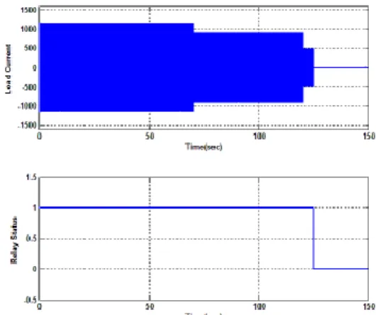
is removed In the first phase 190 MW to 150 MW load is reduced In 70 seconds and 70 MW in the second phase is done in 120 seconds and Relay behavior is observed. Figure 3 shows the current and the relay under different load conditions show.
3
In this simulation add and reduce the load on the graph for the current time is displayed, In the first stage relay does not trip because the recovery time is 5seconds However, substantial reduction in handling time by as much as 70 megawatts, the relay will trip Figure 4 shows the behavior of the output frequency.
Figure 4. Output frequency behavior 4.2 Case2
In the second, the relay behavior under transient conditions to be observed, One of the stops once again and then comes in 5 seconds. In this case, the system in
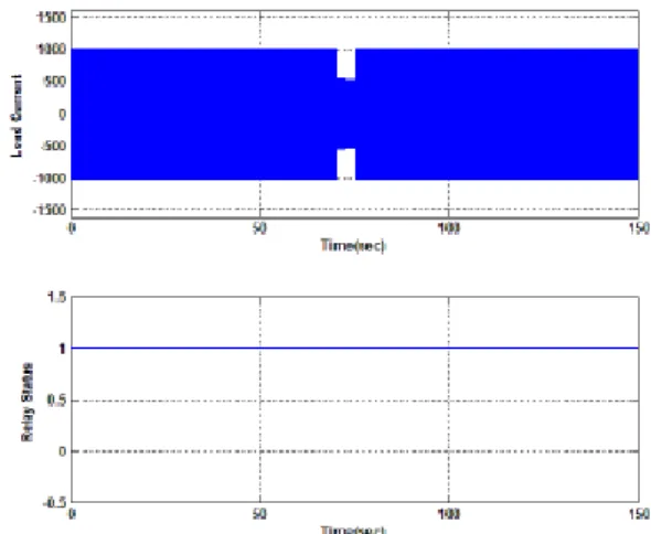
seconds from 169 MW to 80 MW reduced 70. However, in 75 seconds, 80 MW load on the Figure 5 shows the current and the relay under different load conditions show.
Figure 5. Relay Function (a) current (b) Status relay
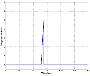
Here it can be seen that the integrator tries to reach the threshold of 5 However, due to transient conditions,
4
Figure 6. Shows integrator
4.3 Case 3
In this case, 40 MW per second, 70 times in addition to the 150 MW added then, in the second 120, the cutting load of 50 megawatts done Figure 7 shows the current and the relay under different load conditions show.
Figure 7. Relay Function (a) current (b) Status relay
In the first stage relay does not trip. However, the 50-megawatt heavy load increase relay will be handling the arrangements. Figure 8 shows the electrical frequency
behavior.
Figure 8. Output frequency
5
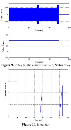
In this case, the relay behavior under transient conditions to be observed. In this case, the ground state of the system load of 150 MW with an increase of 80 MW in 70 seconds, change. But in the second 74, the 80-megawatt returns. In the second phase, 80 times persecond, 120 MW will be added to infinite time. Figure9 shows the current and the relay under different conditions.
Figure 9. Relay (a) the current status (b) Status relay
Figure 10. integrator
Figure 10 shows integrator, Here can be seen that the integrator tries to reach the threshold of 5.
However, due to transient conditions, integrator cannot be more than 5, so the relay does not trip. However, in the second stage integrator 5 and reaches the threshold value so his trip relays.
Conclusion
As this study found that high-frequency relay vital role in protecting and down frequency generators and power systems, and by changing the frequency of the variation in the arrival times and will also protect the generator. And note that the digital relays, electromechanical relay is superior in terms of accuracy and speed. High frequency changes can lead to a complete shutdown and power system blackouts due to the frequency instability due to an imbalance of supply and demand or N-1 is possible. After distributed generation and island issues, relaying frequency may again be important for researchers and industrialists.
References
[1]. ABB. Solid State Under Frequency Relay. Avaialble from: http:// www 05. abb. com/ global/ scot/scot229.nsf/veritydisplay/294c23 5c 3e 25 ca 9bc 1256e d9 0047 c1a1/$file/sdf-1_ib41-504b.pdf Access on: 10 Sept 2012, 2010.
[2]. Aman, M. M., et al. Digital Directional and Non-Directional Over Current Relays: Modell and Performance Analysis, NED University Journal of Research, 2011.
[3]. Aman, M. M. et al. Modeling and Simulation of Reverse Power Relay for Generator Protection. In 2012 IEEE International Power Engineering and Optimization Conference (PEOCO2012), Melaka, Malaysia: 6-7, 2012.
5
digital negative sequence relay for unbalanced protection of generator, in Power Engineering and Optimization Conference (PEDCO) Melaka, Malaysia, Ieee International, 2012.[5]. Areva, MiCOMP921/P922/P923Voltageand Frequency Relays (Technical Guide) Availablefrom:ftp://ftp.areva-
td.com/P92x_EN_T_F22.pdf.
[6]. Bright, C. G. COROCOF: comparison of rate of change of frequency protection. A solution to the detection of loss of mains," in Developments in Power System Protection, 2010.
Sevent International Conference on (IEEE).
[7]. Bright, C. G. COROCOF: comparison of rate of change of frequency protection. Asolution to the detection of loss of mains, in Developments in Power System Protection, Seventh International Conference on(IEE), 2001.
[8]. Butler, S. UK Electricity Networks The nature of UK electricity transmission and distribution networks in an intermittent renewable and embedded electricity generation future, 2009.
[9]. Girgis, A., Ham, F.M. A new FFT-baseddig it alfrequency relay for loads hedding, Power Apparatus and Systems, IEEE Transactions on, 1982.
[10]. Kundur, P., et al. Power systemstability and control vol. 4: McGraw-hill New York, 1994.
[11]. Lobos, T. and Rezmer, J. Real-time determination of power system frequency, Instrumentation and Measurement, IEEE Transactions on, 2009.
[12]. Lobos, T., Rezmer, J. Real-time determination of power system frequency, Instrumentation and Measurement, IEEE Transactions on ,1997.
[13]. MATLAB File Exchange. Author: Muhammad Mohsin Aman. Available from:
[14]. Standard for interconnecting distribute dresources with electric power systems. IEEE Standards Coordinating Committee 21, 2003.