An Energy Based Fuzzy Logic Dc-Link Voltage Controller For Three Phase
DSTATCOM To Compensate AC Loads
A.Ranganadh
1,V.Hari babu
2Email:
1[email protected],
2[email protected]
1
PG Student, Department of EEE, Prakasam Engineering College, kandukur,India
2
Associate Professor, Prakasam Engineering College, kandukur,India
Abstract--- it is very important to compensate the transient response of DSTATCOM for unbalanced and nonlinear loads. Majorly the dc link voltage will be varied, when any small change in the load side. The proper operation of DSTATCOM is achieved with the help of the proportional integral controller (PI) is used. But the transient response of this controller is slow, Because the multiplication of the gains are more In this paper implement the energy based fuzzy logic controller with fast reference voltage generation to regulate Unbalance voltage in three-phase system. Also improves the Power Quality of the 3-phase unbalanced and nonlinear loads. One of the main advantages of Fuzzy control over conventional controller is the inaccuracies of the sensors on the system performance can be reduced by adding additional rules, this reduces the need for costly sensors and cost of the control system is reduced without a compromise in performance. The simulation results show a very good performance
Index Terms—DC-link voltage controller, distribution static compensator(DSTATCOM), harmonics, power quality (PQ), fuzzy logic, power factor
I.INTRODUCTION
In general the power system network consists of unbalanced and nonlinear loads. These loads are creates majorly power quality problems in the network. Power
to these currents causes a overheating of the machine. and they causes poor power factor, voltage interference and more harmonic distortion .to overcome those problems in power system network we are implementing the custom power devices they are UPFC,SSSC, DSTATCOM. Generally DSTATCOM device is used because it should have shunt controlling technique. The flexible ac transmission system allows a greater control of power flow and a secure loading of transmission lines to levels nearer to their thermal limits, among other benefits.
To mitigate the PQ problems in the load conventional DSTATCOM is prefered.and to supply the dc loads from its dc link as well. The rating and design of the VSI decides the sharing if the ac and dc bus. The DC link with this DSTACOM supports instantaneous compensation along with it supplies dc loads also.
However, when the dc link of the DSTATCOM supplies the dc load as well, the corresponding dc power is comparable to the average load power and, hence, plays a major role in the transient response of the compensator. Hence, there are two important issues. The first one is the regulation of the dc-link voltage with in prescribed limits under transient load conditions. The second one is the settling time of the dc–link voltage controller. Conventionally, a PI controller is used to maintain the dc-link voltage
experimental verifications are given to prove the efficacy of this energy based fuzzy logic controller.
II. COMPENSATION OF AC AND DC LOADS BY
USING DSTATCOM
Due to the simplicity, the absence of unbalance in the dc-link voltage and independent current tracking with respect to other phases, a 3-phase H-bridge VSI topology is shown in Fig. 1
The above figure shows a three-phase, four-wire compensated system using an H-bridge VSI topology-based DSTATCOM compensating unbalanced and nonlinear ac load. In addition to this, a dc load is connected across the dc link. The DSTATCOM consists of 12 insulated-gate biploar transistor (IGBT) switches each with an antiparallel diode, dc storage capacitor, three isolation transformers, and three interface inductors. The star point of the isolation transformers is connected to the neutral of load and source. The Fig.1 Three-phase, four-wire compensated system using the bridge VSI topology-based DSTATCOM. H-bridge VSIs are connected to the PCC through interface inductors. The isolation transformers prevent a short circuit of the dc capacitor for various combinations of the switching states of the VSI. The inductance and resistance of the isolation transformers are also included in and the source voltages are assumed to be balanced and sinusoidal. While compensating, the DSTATCOM maintains the balanced sinusoidal source currents with unity power factor and supplies the dc load through its dc bus.
During normal condition the source is going to generate balanced and sinusoidal voltage. If there is a sudden decrease/increase of the unbalanced and nonlinear load in this type of system, it causes unbalance and harmonics in the load current [4], [5]. These currents are going to be injected at the PCC with the help of DSTATCOM. The operation of the compensator is supported with the help of the dc capacitor and this supplies the required dc load [6] [7].
III.MODELINGOFTHEDSTATCOM
To calculate the system actual currents,with the help of the proposed DSTATCOM current controllers is as shown bellow.
In order to keep the dc-link voltage of the inverter in the DSTATCOM at an assigned level during operation, the DSTATCOM needs to absorb active power from the power source to supply the power losses and charge the dc-link capacitor in the DSTATCOM. Hence, use of a Proportional-Integral type feedback controller in the
DSTATCOM controller regulates the active current
of the DSTATCOM [13].and three phase currents are required to comparison of base currents. The resultant will beefed to the controllers in the form of voltages .These currents are achieved with the help of following diagram as shown in fig.3
The design of Mamdani type Fuzzy PD controller using Fuzzy Logic tool box in MATLAB is demonstrated [8]. The membership functions of input (error and rate of change of error) and output variables (control action) and rule base are defined in the tool box. The PI controller block in the control scheme of the DSTATCOM was replaced by the designed Fuzzy Inference System (FIS). The DSTATCOM was then simulated for the same load with all other parameters maintaining the same.
A. Fuzzy Control Scheme For D-Statcom
Fuzzy logic (FL) controller is the heart of fuzzy set
rather than numerical variables. This control technique relies on human capability to understand the systems behavior and is based on quality control rules. Fuzzy Logic provides a simple way to arrive at a definite conclusion based upon vague, imprecise, noisy, ambiguous, or missing input information.
The structure of an FLC is represented in Fig.4 and comprises of four principal components
The Fuzzification interface will converts input data into suitable linguistic values.
The Knowledge Base is consists of a data base with the necessary linguistic definitions and control rule set.
A Decision Making Logic will, simulating a human decision process, and interface the fuzzy control action from the knowledge of the control rules and the linguistic variable definitions. Defuzzification interface is yields a non-fuzzy
control action from an inferred fuzzy control action.
B .MEMBERSHIP FUNCTIONS
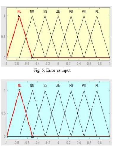
Fig. 5: Error as input
Fig. 6: Change in error as output
In this fuzzy logic controller rules are designed based on the membership functions. Those rules are represented with following notations and rules are arranged in Table.1 as shown in bellow
The two inputs were represented by sets of seven membership functions and expressed in linguistic values as negative large (NL), negative medium (NM), negative small (NS), zero (ZE), positive small (PS), positive medium (PM), and positive large (PB). The range for the “error” input was set and that for “change of error” was set.The AND method used during interpretation of the IF-THEN rules was “min” and the OR method used was “max.” Also, “min” was used as the implication method whereas the “max” method was used for aggregation [9], [10]. The 49 fuzzy IF-THEN weighted rule base was designed to maintain the capacitor voltage constant by providing the required reference current amplitude.
V.SIMULATION STUDIES
To analyze the performance of system we have designed a Matlab/Simulink model as shown in the fig. Here a three phase source is connected to the unbalanced load and non-linear load, the dstatcom is connected in shunt at the point of common coupling. The main intention here is to control the dc-link voltage. Whenever if there is any change in load, this causes the variation in the dc-link voltage from its reference value. In order to bring back the dc-link voltage to its reference value here we are considering three cases (i) DC-link voltage control with conventional PI controller (ii) DC-link voltage control with Energy based PI controller (iii) DC-link voltage control with Energy based Fuzzy Logic controller. On these three conditions we are getting the variation of dc-link voltage at t=0.4 sec and at t=0.8 sec. The explanation of control circuit and the simulation results are as follows.
Fig. 7 Simulink diagram of the system with
A. DC-Link voltage control with conventional PI controller:
The controlling circuit with conventional PI controller is shown in the fig below.
Here we are going to consider two cases (i) when there is sudden load reduction and (ii) when there is sudden increase in load to full load condition. In the first case if there is a sudden reduction in the load then the dc-link capacitor will absorb the extra power from the source. Fig shows the increase in the voltage of DC-Link capacitor above the reference value.
Then the PI controller comes into action and brings the dc-link capacitor voltage to its reference value in 0.04 sec. In the second case if the load comes back to its full load condition then the capacitor has to supply the required voltage. Hence there will be a reduction in the voltage from reference value. This will again bring back to its reference value with the help of conventional PI controller.
B. DC-Link voltage control with Fuzzy controller:
The controlling circuit with Fuzzy controller is shown below.
C.DC-Link voltage control with Energy based Fuzzy controller:
Here we are taking the square of the dc voltage and its reference and the resultant after comparing these two is passed through the fuzzy controller. Then the dc load power is calculated. Here also we will consider the same two cases as above. By using the energy based fuzzy controller here we are bringing the voltage to its reference value in 0.002 sec after the changes in load.
VI COMPARISION
The bellow fig.14 shows that comparison between dc link voltages for compensating variation of loads. In above, graph1 (refer fig.9) represents the settling time is 0.42sec.graph 2 (refer fig.11) represents the settling time is 0.402sec. Graph 3 (refer fig.13) represents the settling time is 0.4002sec. The conclusion of the above graph is energy based fuzzy control is better one and it has improvement of power factor is 0.98 that is shown in bellow
bellow
Fig. 17, 18, 19 shows the FFT analysis of the load voltage for conventional PI, Energy based PI and with Fuzzy Logic controllers. The comparison table between different controllers is shown below.
VII. CONCLUSION
REFERENCES
[1] N. Hingorani, “Introducing custom power,” IEEE Spectrum., vol. 32, no. 6, pp. 41–48, Jun. 1995.
[2] W. M. Grady and S. Santoso, Proc. IEEE Power Eng. Rev. Understanding Power System Harmonics, vol. 21, no. 11, pp. 8–11, 2001.
[3] A. Ghosh and G. Ledwich, Power Quality Enhancement Using Custom Power Devices. Norwell, MA: Kluwer, 2002.
[4] A. Dell ‘Aquila, M. Liserre, V. G. Monopoli, and P. Rotondo, “An energy-based control for an n-H-bridges multilevel activerectifier,” IEEE Trans. Ind. Electron., vol. 52, no. 3, pp. 670–678, Jun. 2005.
[5] M.K.Mishra, A.Ghosh, and A.Joshi, “A new STATCOM topology to compensate loads containing ac and dc components,” in Proc. IEEE Power Eng. Soc. Winter Meeting, Singapore, Jan. 23–27, 2000, vol. 4, pp. 2636–2641.
[6] Alireza Nami Hoda Ghoreishy, Department of Power, Mazandaran University, Babol, Mazandaran, Iran “A Novel Random Hysteresis Current Control for a Single-Phase Inverter.”
http://itee.uq.edu.au/~aupec/aupec06/htdocs/content/pdf [7] Mahesh K. Mishra, Member, IEEE, and K. Karthikeyan ,A Fast-Acting DC-Link Voltage Controller for Three-Phase DSTATCOM to Compensate AC and DC Loads, IEEE Transactions On Power Delivery, Vol. 24, No. 4, October 2009.
[8] Jon C. Ervin, Sema E. Alptekin and Dianne J. DeTurris, “Optimization of the Fuzzy Logic Controller for an Autonomous UAV,” (EUSFLAT) Conference: Barcelona, Spain (2005).
[9] “Neuro-Fuzzy based power quality improvement in a three phase four wire distribution system using D-STATCOM” by E.Babu,R.Subramanyam in International Electrical Engineering Journal(IEEJ) Vol. 4 (2013) No. 1, pp. 953-961 ISSN 2078-2365.
[10] Sheroz Khan, Salami Femi Abdulazeez, Lawal Wahab Adetunji, AHM Zahirul Alam,Momoh Jimoh E. Salami, Shihab Ahmed Hameed, Aisha Hasan Abdalla and Mohd Rafiqul Islam , “Design and Implementation of an Optimal Fuzzy Logic Controller Using Genetic Algorithm,” in Journal of Computer Science 4 (10):2008.