329
DESIGN AND IMPLEMENTATION OF COMMAND SCHEMES TO
AUTOMATE WATER SUPPLY INSTALLATIONS IN THE FOOD INDUSTRY
GLODEANU MIHNEA, ALEXANDRU TUDOR, VASILE CRISTIAN
University of Craiova, Faculty of Agriculture
Keywords:water supply installations, food industryd, command schemes
ABSTRACT
Water is an indispensable element of life, being an important factor in almost all industrial manufacturing processes.
In the food industry water has multiple uses, during the technological process as: raw and auxiliary material; water for washing; sorting water; water cooling and transport of various materials etc.
The water needs of various sub-sectors of the food industry is determined by production processes, as well as according to the diversity of manufacturing technologies (for example: bakery products - approx. 0.9 m3/t; slaughterhouses - approx. 3.5 m3 per
animal slaughtered; potato alcohol - approx. 5 m3/t; etc.).
Storing water in tanks is projected to water supply installations of the units with high water consumption, as well as with fluctuations of consumer flows.
Storage tanks can be open tanks which communicates with the atmosphere and pressure tanks. In their turn, open tanks can be buried, semi-underground or aerial. In order to dimension the water supply installations it will determine the necessary water.
The role of storage tanks is:achieving offsetting changes of the water flow;ensuring service pressure water to consumersand the stock water in case of damage to the capture and treatment installations; ensuring the water reserve for fire fighting etc.
INTRODUCTION
Due to quite large interruptions in the operation of the pumping installations the water level in the storage tanks varies in large limits and the water reserve (in the case of hazard warning of the installation) is not ensured. To avoid these situations it is necessary to use large capacity tanks, or increasing the number of start-up of the pumping installation (Banu C. and collab., 2002; Iordache G., 2004).
In the food industry the automation of pumping installations has favorable consequences on the specific working parameters of these installations and also on the working regime of the actuating electric motor. The normal functioning of a pumping installation can be ensured only by equipping the storage tanks with auto-level systems.
Automating pumping installations allow placing in service of the installation when the water in the tank reaches a certain level, or when water pressure in the tank falls below a certain value (Iordache G., 2004; http://www.ac.tuiasi.ro/~lmastacan/wp-content/uploads/L13-Studiul-sistemelor-de-reglare-a-nivelului.pdf).
By means of an automation system functioning of lifting pump water to the tank is commanded depending on the water level in the tank.
One such type of automation system comprises the following main components: contactor for remote operation in order to start and stop the electric motor for driving the pump; level transducers with electrodes, floating system or membrane; microswitch (Bianchi C. and collab., 1976; Fink D., Wayne Beaty, 2006; Popescu Lizeta, 2008, Vlad C. and collab., 2009). The pump that will feed the tank work in intermittent regime and require a adequately flow to ensure maximum daily water demand (for an operating time of 14 to 20 hours/day).
330
MATERIAL AND METHODS
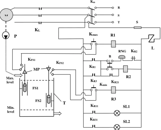
Figure 1 presents the automatic control scheme for a supply installation equipped with open tank.
Fig. 1. Automatic control scheme for a supply installation equipped with open tank.
To indicate the maximum and minimum level, the tank is provided with two float systems (FS1 and FS2). These actuate the rods (monted on the float systems), which by means of metal pieces (MP) achieve closing or opening the contacts KFS1 and KFS2 (and thus the contacts Kmax or Kmin) (
www.rasfoiesc.com/inginerie/electronica/Instalatii-pentru-semnalizarea18.php;
http://www.creeaza.com/tehnologie/constructii/instalatii/INSTALATII-PENTRU ALIMENTAREA-212.php).
The scheme must be designed such that, the signaling lamps SL1 and SL2 indicate permanently the presence of one of the two states (maximum level, respectively minimum level) (
http://www.ac.tuiasi.ro/~lmastacan/wp-content/uploads/L13-Studiul-sistemelor-de-reglare-a-nivelului.pdf).
The installation operates in the following way:
- it is closing the power switch from power supply (Km); in this way the installation is ready to enter into operation;
- when the water level from the tank rises above the maximum admissible level, the float system FS1 can close the contact Kmax; in this way it excites the relay R1, which by means of contact KR1 supply power to the ringer RNG; at the same time the contact KR11 closes and the signaling lamp SL1 light (signaling this situation); to silence the alarm sound is necessary to actuated the button B (the relay R2 being excited and the contact KR21 closes); closing the contact Kmax will determine the opening of contacts L (from the circuit of the contactor L), so the electric engine (M) and pump (P) will not work (Glodeanu M. and collab., 2014);
- the minimum level is indicated in the same way, by means of contact Kmin, which when closing excites the relay R3 (which is acting through the contact KR3 on the same ringer); the ringer is similarly disconnected, using the button B; the signaling lamp SL2 is turned
S
L
R3
SL2 SL1
KR11
KR31
B
KR1
T
Max. level
Min. level
FS1
FS2
RNG
R2
Kmin
KR3
KR2
KR21
KFS1
KFS2
R1 KL
Kmax
R
S
T
Km
M
P
331
on; alsoin this case closing the contact Kmin will determine the opening of contacts L (from the circuit of the contactor L), so the engine and pump will not operate;
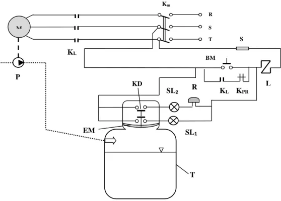
Figure 2 presents the automatic control scheme for a supply installation equipped with closed tank.
Fig. 2. Automatic control scheme for a supply installation equipped with closed tank.
The installation is provided with a pressure relay, which is mounted at the upper of the tank. The elastic membrane of the pressure relay is coupled to a double contact A (which is mounted in the circuit of the contactor L) ((Bianchi C. and collab., 1976; Vlad C. and collab., 2009).
As long as the tank pressure is below the prescribed maximum value, the double contact KD close the coil circuit of the contactor L. In this situation the electric engine (M) is functioning and the pump (P) will supply with water the tank (the signaling lamp SL1 light, but the ringer (R) is turned off).
When water in the tank reaches a certain level, the value of the pressure increase, the elastic membrane (EM) pushed up and the contact KD which determines the opening of the coil circuit of the contactor L (and thus the interruption of pumping water into the tank). In the same time the contact KD will close the circuit in which are integrated the signaling lamp SL2 and the ringer (these becoming active) (Bianchi C. and collab., 1976; Fink D., Wayne Beaty, 2006; Popescu Lizeta, 2008).
The installation is provided with a manual command achieved with the start button BM. The normally closed contact KPR of the presuure relay (mounted in parallel with BM contact) does not allow the functioning of the installation when the pressure in the tank has reached the maximum value (Bianchi C. and collab., 1976; Glodeanu M. and collab., 2014;
www.rasfoiesc.com/inginerie/electronica/Instalatii-pentru-semnalizarea18.php);
RESULTS AND DISCUSIONS
To verify the correct operation of the command schemes (to ensure the starting and stopping of the electric engine that acts the pump, in order to avoid the states maximum
KL
SL2
BM
L
EM
R
S
R
S
T
Km
M
T
KPR
KL
SL1
P
332
level, respectively minimum level) there were mounted acoustic devices and signaling
lamps. These lamps were mounted in the coil circuit of the contactor for coupling - decoupling the electric motor (controlled by this circuit).
The results of the tests concerning the operation of the automatic control systems are shown in table 1.
The advantage of stopping – starting of the electric motor, to avoid the two states consists in providing good conditions for conducting different technological processes and also in preventing abnormal situations (that can cause accidents or damage).
Table 1
Results of the tests concerning the operation of the designed control systems Automatic control scheme for a supply installation equipped with open tank
Stages State level Signalling lamp
status (for maximum level)
SL1
Signalling lamp status (for minimum level)
SL2
Ring state Status of electric
motor
1 maximulm
level
ON OFF Connected STOP
2 Intermediate
level
OFF OFF Not
connected
STOP
3 minimum
level
OFF ON Connected START
Automatic control scheme for a supply installation equipped with closed tank
Stages State level Signalling lamp
status (for maximum level)
SL2
Signalling lamp status (for intermediate
level) SL1
Ring state Status of electric
motor
1 Intermediate
level
OFF ON Not
connected
START
2 maximulm
level
ON OFF Connected STOP
CONCLUSIONS
- Automation of pumping installations has favorable consequences on the specific working parameters of these installations and also on the working regime of the actuating electric motor;
- This requirement imposed to design and implementation of automatic control schemes, to ensure the starting and stopping of the electric engine that acts the pump, in order to avoid the following states: maximum level, respectively minimum level;
- Checking the work process of the command scheme for a supply installation equipped with open tank has indicated that it is ensured the starting and stoping of the electric engine, in accordance with the water level in the tank;
- Checking the work process of the command scheme for a supply installation equipped with closed tank has indicated that water supply is ensured as long as the tank pressure isbelow the prescribed maximum value;
- for both the command schemes the functioning of signaling - warning devices was adequate, indicating correctly the working states.
BIBLIOGRAPHY
1. Banu C. and collab., 2002, Food engineer manual, DIDACTIC AND PEDAGOGICAL Publishing House, Bucharest.
333
3. Fink D., Wayne Beaty, 2006, Electrical Engineering, MCGRAW-HILL EDUCATION-EUROPE Publishing House.
4. Glodeanu M. and collab., 2014, The design and realization of a control scheme for a transport system with trailers used in the food industry, Annals of University of Craiova, series Agriculture, Montanology.
5. Glodeanu M. and collab., 2014, The design and realization of a control scheme of a three-section conveyor belts used in the food industry, Annals of University of Craiova, series Agriculture, Montanology.
6. Iordache G., 2004, Machinery for the food industry, MATRIX ROM Publishing House, Bucharest.
7. Popescu Lizeta, 2008, Electrical Equipments, ALMA MATER Publishing House, Sibiu.
8. Vlad C. and collab., 2009, Elements of Electrical Engineering, Laboratory Guide, GALAȚI UNIVERSITY PRESS Publishing House, Galați.
9. ***
http://www.creeaza.com/tehnologie/constructii/instalatii/INSTALATII-PENTRU-ALIMENTAREA-212.php
10. *** www.rasfoiesc.com/inginerie/electronica/Instalatii-pentru-semnalizarea18.php.