DOI: 10.14810/ijscmc.2015.4404 39
OPTIMAL
PID
CONTROLLER
DESIGN
FOR
SPEED
CONTROL
OF
A
SEPARATELY
EXCITED
DC
MOTOR:
A
FIREFLY
BASED
OPTIMIZATION
APPROACH
Pikaso Pal
1, Rajeeb Dey
2, Raj Kumar Biswas
2, Shubhashish Bhakta
21 Department of Electronics and Instrumentation Engineering, National Institute of Technology Agartala, Tripura-799046, India
2 Department of Electrical Engineering, National Institute of Technology Silchar, Assam-788010, India
ABSTRACT
This paper presents a new approach to determine the optimal proportional-integral-derivative controller parameters for the speed control of a separately excited DC motor using firefly optimization technique. Firefly algorithm is one of the recent evolutionary methods which are inspired by the Firefly’s behavior in nature. The firefly optimization technique is successfully implemented using MATLAB software. A comparison is drawn from the results obtained between the linear quadratic regulator and firefly optimization techniques. Simulation results are presented to illustrate the performance and validity of the design method.
KEYWORDS
Separately excited DC motor; Linear Quadratic Regulator; Optimal control; Firefly Algorithm; PID controller Tuning component
1.
INTRODUCTION
40
which is illustrated in this literature. The steps for obtaining the optimized PID gains using the LQR technique are presented in [2]. In this note, an attempt is made to implement the similar procedure for a separately excited dc motor.
Several researchers have implemented heuristic optimization techniques till date. Yadav et al. [3] presented the Genetic algorithm (GA) based PID control for DC motor. GA is inspired by natural selection and evolutionary genetics but degradation is noticed in GA performance when applied to highly epistatic objective functions [4]. Nasri et al. [5] presented the optimal designing of PID control for a linear brushless DC motor using PSO algorithm. Particle swarm optimization (PSO) is a population based search. The major advantages of PSO is its easy implementation and computational efficiency. It is an effective search algorithm which needs to optimise a very few parameters. But major drawback of PSO is its very weak local search ability which results in a fast and premature converge in mid-optimum points [6]. Pal et al. [7] concluded that both the PSO and Firefly algorithm (FFA) performs almost similar in approaching the optimum, provided the process is free of noise. But FFA proves effective and takes less time to reach optimum value in solving non-linear optimization problems and functions in presence of noise. The comparison in performance of FFA with bees algorithm has been investigated in literature [2]. Given a noisy unconstrained mathematical models with continuous design variables the task is to find the optimal solution. A result proves that the efficacy of FFA lies in its unique behavior of attractiveness.
The main objective of this paper is to present an effectiveness of FFA in designing an optimal PID controller for speed control of separately excited DC motor. The remainder of this paper is organized as follows: Section 2 gives a detailed description of the system. Section 3 presents an overview of the optimal tuning rules. MATLAB simulation results are discussed in Section 4. Section 5 finally concludes the paper.
2.
SYSTEM
DESCRIPTION
41
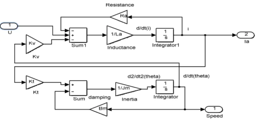
Fig.1 shows the DC motor simulink model. The DC motor specification is given in Table 1. By using the electrical equation and the mechanical equation, the armature current and the angular velocity can be measured which describes the DC motor system.
1
a a v
a a
a a a
di R K
i
dt = L − L ω + L U (1)
a t m
a a
m m
d K B
i external
dt J J disturbances
ω
ω
= − + (2)
where iais the armature current and ωa is angular velocity.
In this paper, the external disturbance is considered to be equal to zero. Assumingia =X1and
2
a X
ω = and converting these equations into states space form, we get
1 1
2 2
1
0
a v
a a
t m
m m
a
R K
L L
X X
d
X K B X
dt
J J
L U external disturbances −
= +
−
+
(3)
And the output equation can be written as,
[
]
12
0 0 1
0
X
y U
X
= +
(4)
Table1. Separately excited DC motor specification
DC motor parameter Value Motor Rating 3 HP Dc Supply Voltage 220 V Motor Rated Current 4.3 A Armature Resistance,Ra 0.6 Ω
Armature Inductance,La 0.008 H Inertia Constant, J 0.011 Nm^2 Damping Constant, B 0.004Nm/rad/sec
Torque Constant,Kt 0.55 Back Emf Constant,Kb 0.55
42
The matrices A B C and D, , , are obtained by considering the specification of separately excited DC motor presented in Table 1 and using equations (3) and (4) as follows
[
]
75 68.75 125 0
50 0.3636 0 90.9
0 0
0 1
0 0
A B
C D
− −
= =
− −
= =
(5)
The system transfer function for the separately excited DC motor is then given by
( )
( )
26250 75.36 3465
Y s
U s =s + s+ (6)
3.
TUNING
RULES
3.1. LQR based PID Tuning
This section presents the LQR based tuning of PID parameters for a separately excited dc motor [8]. Fig. 2 shows the LQR based PID tuning of second order system.
Figure 2. LQR based PID tuning of second order system [8].
The reference input r(t) is considered to be zero as the external set point does not affect the controller design in the state feedback regulator design. With no change in the set point, the relation y t
( )
= −e t( )
is valid for a standard regulator problem. Hence the equation (6) corresponds to( )
( )
( )
( )
26250 75.36 3465
Y s E s
U s s s U s
−
= =
+ + (7)
LQR formulation considers the quadratic cost function given below to be minimized.
1 s
s
k s2+ 2ξoω
n os + ω
43
( )
( )
( )
( )
0
T T
J X t QX t u t Ru t dt
∞
=
∫
+ (8)The minimization of above cost function results in an optimal control input given by
( )
1( )
(t)
T
u t = −R B PX t− = −FX (9)
whereP is a symmetric positive definite solution of continuous algebraic Ricatti equation. The algebraic Ricatti equation is given by,
1
0
T T
A P+PA−PBR B P− +Q= (10)
Equation (7) can be rewritten as
( )
( )
( )
( )
2
75.36 3465 6250
s E s + sE s + E s = − U s (11)
75.36 3465 6250
e+ e+ e= − u
&& & (12)
Let the state variables be
( )
( )
( )
1 , 2 , 3
de t
x e t dt x e t x
dt
=
∫
= = (13)Hence equation (12) reduces to
3 75.36 2 3456 2 6250
x& + x& + x = − u (14)
Writing equation (14) in states space form
1 1
2 2
3 3
0 1 0 0
0 0 1 0
0 3465 75.36 6250
x x
x x u
x x
= +
− − −
&
& &
(15)
[
]
11 12 13
1 1
21 22 23
31 32 33 0 0 6250
T
P P P
F R B P R P P P
P P P
− −
= = −
(16)
[
]
1
13 23 33
6250R− P P P
44
Weighting matrix Q is symmetric positive definite and the weighting factor R is a positive constant. In general, Q is varied, keeping R fixed to obtain an optimal control signal from the linear quadratic regulator.
( )
( )
[
]
1
1
13 23 33 2
3
6250
x
u t Fx t R P P P x
x − = − = (18)
For the closed loop system the characteristic polynomial is given by [8]
( )
23 1 2 2 1 2 1 2
33 23 13
2 n 0
s ξο R k P− s ωο R k P− s R k P−
+ + + + + = (19)
In terms of desired damping ratio and natural frequency, the characteristic polynomial for a closed loop system is given by [8]
(
)
( )
2( ) ( )
2 2( )
33 2
2 c c c 2 c c c c 0
n n n n
s + +m ξ ω s + ω + m ξ ω s+mξ ω = (20)
Comparing the equations, we get
( )
3c c n i m k k ξ ω
= (21)
( )
2( ) ( )
2 22 c c n n p m k k ο
ω + ξ − ω
= (22)
(
2)
c 2 nd
m k
k
ο ο
ξ ξ ω
+ −
= (23)
where, 1 13
i
k =R KP− , 1
23
p
k =R KP− , and 1 33
d
k =R KP− . The Linear Quadratic regulator (LQR) method considers m=9, ξc =1 and ωnc=30 to determine the optimal values of kp, ki and kd.
3.2. Firefly Algorithm
The firefly algorithm (FA) is a nature-inspired metaheuristic algorithm. The formulation of this algorithm is inspired by the flashing behaviour of fireflies [7]. In 2007 Xin-She Yang formulated this firefly algorithm assuming
1. All fireflies are unisexual, so the flash of firefly’s act as a signal system to attract other fireflies.
45
The attractivenessβ of a firefly is inversely related to the distance r and is given by, r2
eγ
ο
β β −
=
where βοis the attractiveness at r=0. The distance r or rij between any two fireflies i and j at
positions xiand xj respectively is be given by rij = ||xi- xj||, i.e the difference between the positions
of two fireflies. The movement of a firely i with respect to another brighter firefly j is determined by,
(
)
2
1 rij
t t t t t
i i j i t i
x x βοe γ x x α ε
−
+ = + − +
where the first term denotes the present position of the firefly, the second term is due to the attraction and the third term introduces the randomization in the movement. αt is the randomization parameter which can be tuned to vary with the iteration
counter t during iterations as given by t
t ο
α =α δ , where 0 <
δ
<1, and εit is a vector of random numbers drawn from a gaussian distribution or uniform distribution at time t. The movement of the firefly will become a simple random walk ifβο=0. γ =0 corresponds to no variation and reduces to a variant of particle swarm optimization.3.2.1 Implementation of Firefly optimized PID controller
In PID controller design method, the most common performance criteria are the integral of absolute error (IAE), the integral of time weighted absolute error (ITAE), the integral of squared error (ISE) and the integral of time weighted square error (ITSE). In this paper, the integral of absolute error (IAE) is the fitness function to be minimized.
The IAE criterion is given by | | , where e is the difference between the reference speed and the actual speed.
The following section describes the pseudo code [7].
Step1: Initialize the algorithm parameters
Step2: Define the integral absolute error as the objective function. Step3: Generate an initial population of fireflies x ii
(
=1, 2,....,n)
Step4: Determine light intensity for xi by calculating f x
( )
iStep5: Define light absorption coefficient γ
While t<Maximum generation
Make a copy of the generated Firefly For i=1:n for all n fireflies For j=1:n for all n fireflies
If
(
Ij >Ii)
Move fireflies iand jaccording to their attractiveness.
Evaluating new solutions and updating the light intensity for the next iteration
End if
End for j
End for i
Sorting the fireflies to find the present best End while
46
4.
RESULTS
AND
DISCUSSION
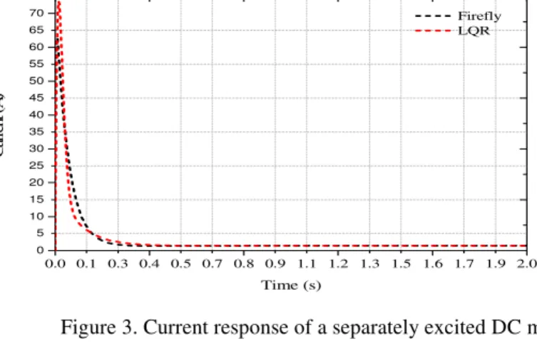
Figure 3. Current response of a separately excited DC motor.
Figure 4. Speed response of a separately excited DC motor.
The optimal value of the gainkp, kiand kd and the time domain response obtained using linear
quadratic regulator and firefly algorithm is tabulated below in table 2 and table 3 respectively. The current and speed response of seperataly excited DC motor are shown in Fig. 3 and Fig. 4 repectively. It is comprehended from the study that the FFA provides a better and fast response in terms of time domain specifications like rise time, settling time, peak time as compared to the LQR technique.
Table 2. Optimized PID Parameter
p
k ki kd
LQR 2.181604721 38.88 0.040744652
Firefly 4.6650 44.4648 0.2070
0.0 0.1 0.3 0.4 0.5 0.7 0.8 0.9 1.1 1.2 1.3 1.5 1.6 1.7 1.9 2.0
0 5 10 15 20 25 30 35 40 45 50 55 60 65 70 75
C
u
rr
en
t
(A
)
Time (s)
Firefly LQR
0.0 0.1 0.3 0.4 0.5 0.7 0.8 0.9 1.1 1.2 1.3 1.5 1.6 1.7 1.9 2.0
0 100 200 300 400 500 600 700 800 900 1000 1100 1200 1300 1400 1500 1600 1700 1800 1900
S
p
ee
d
(
rp
m
)
Time (s)
47 Table 3. Time Domain Parameter
Rise Time Settling Time
Peak Time
Over- shoot
Under- shoot
Steady state error LQR 0.1412 0.2986 1.5 1.2009e-06 0 0
Firefly 0.1233 0.2387 1.2 8.5653e-05 0 0
The Firefly algorithm determines the optimal PID parameters with an upper bound forkp, ki and d
k as 10, 100 and 1 respectively and the lower bound forkp, ki and kd as 0, 0 and 0.01 respectively. The parameters for the Firefly algorithm are presented in Table 4.
Table 4. Parameter of Firefly Algorithm
Number of Fireflies (n) 5
Maximum Generation 100
Alpha (randomness) 0.5
Beta min (initial attractiveness) 0.2
Gamma (absorption co-efficient) 0.5
No. of iterations 500
5.
CONCLUSIONS
In this paper Firefly optimization technique is implemented to determine the optimal PID controller parameters for a separately excited dc motor. The objective function considered for PID controller design is integral of absolute error. The MATLAB simulation results shows that the proposed algorithm improves the transient performance of the system as compared to the LQR technique with a reduced rise time, settling time, peak time. Moreover, the LQR technique needs time consuming mathematical calculations. In this paper, the external disturbance is set to zero. Our future scope of work will be to carry out the simulation of the above system in presence of external disturbances.
REFERENCES
[1] Soni, Ritu. Singh, D.B.V. Pandey, Pramod. & Sharma, Priyanka (2013) “Simulation of optimal speed control for a DC motor using conventional PID controller and Fuzzy logic controller”, International Journal of information and computation Technology, Vol. 3, No. 3 , pp 181-188.
[2] Anderson, B.D.O. & Moore, J.B (1989) “Optimal control: Linear quadratic methods”, Prentice –Hall International, Inc., Englewood Cliffs, NJ.
48 [4] He, Jian-Bo., Wang, Qing-Guo., Lee, Tong-Heng.: (2000) “PI/PID controller tuning via LQR
approach”, Chemical Engineering Science, Vol. 55, No. 13, pp 2429-2439.
[5] Nasri, M. Nezamabadi-pour, H. & Maghfoori, M (2007) “A PSO based optimum design of PID controller for a linear brushless DC motor”, International Journal of Electrical, Robotics, Electronics and Communications Engineering, Vol. 1, No. 2, pp 171-175.
[6] Pinto, A. Elvis, H. Domingues, I. Rocha, L. & Cruz, S (2010-2011) “The Particle swarm optimization algorithm”
[7] Pal, S.K. Rai, C.S. & Singh, A.P (2012) “Comparative study of Firefly Algorithm and Particle swarm optimization for noisy non-linear optimization problems”, International Journal of intelligent systems and applications, Vol. 10, pp 50-57.
![Figure 2. LQR based PID tuning of second order system [8].](https://thumb-us.123doks.com/thumbv2/123dok_us/8039873.2128852/4.918.130.723.583.787/figure-lqr-based-pid-tuning-second-order.webp)