Jurnal Teknologi, 35(D) Dis. 2001: 55–64 © Universiti Teknologi Malaysia
DESIGNING POWER SYSTEM STABILIZER FOR MULTIMACHINE POWER SYSTEM USING NEURO-FUZZY
ALGORITHM
M. F. OTHMAN1, M. MAHFOUF2 & D. A. LINKENS3
Abstract. This paper describes a design procedure for a fuzzy logic based power system stabi-lizer (FLPSS) and adaptive neuro-fuzzy inference system (ANFIS) and investigates their robustness for a multi-machine power system. Speed deviation of a machine and its derivative are chosen as the input signals to the FLPSS. A four-machine and a two-area power system is used as the case study. Computer simulations for the test system subjected to transient disturbances i.e. a three phase fault, were carried out and the results showed that the proposed controller is able to prove its effectiveness and improve the system damping when compared to a conventional lead-lag based power system stabilizer controller.
1.0 INTRODUCTION
Low frequency oscillations occur in power systems due to disturbances. If no adequate damping is available, such oscillations can increase and cause system separation. Power system stabilizers (PSS) are installed in power systems generators to enhance damping [6] and provide supplementary feedback stabilizing signals which extend the power stability limits.
Under the conventional PSSs, the proposed eigenvalue assignment technique is iterative and leads to heavy computations, which give rise to time-consuming com-puter codes [1]. Furthermore, the initialization step is crucial and affects the final dynamic response of the controlled system. From a given set of eigenvalues, different designs can be obtained by simply altering the parameters involved in the initialisation step.
Mathematical programming techniques have been applied to assist in the final criteria of these conventional PSSs [4], however, they disregard conservativeness and cause the number of constraints to increase considerably. The optimization process requires the computations of sensitivity factors and eigen-factors at each iteration. This results in heavy computational tasks and slow convergence. The search process will somehow be trapped in local minima and the solution obtained will not be optimal.
1, 2 & 3
As far as modern control theory is concerned, several approaches have been proposed to improve the PSS design problem; these include optimal control, adap-tive control, variable structure control and intelligent control [2, 4]. The present paper introduces a power stabilizer based on fuzzy logic and ANFIS design control-lers. The influence of the proposed FLPSS design on the dynamic characteristics of the controlled system is investigated. Simulation results to illustrate the effectiveness of the proposed controller are presented. These results have been obtained from a simulation study on a four-machine power network. In this study, the system has been subjected to a severe type of disturbance, i.e. a sudden three-phase short cir-cuit fault at the end of one of the system busbars. This test demonstrates the en-hancement of the transient stability of the system.
In this Fuzzy logic based design, a rule was extracted from a conventional control-ler to give an initial solution. A speed deviation and its derivative are used as an input to the PSS controller. The Neuro-fuzzy technique is used as a second design method. Training data are taken from the output of a conventional controller and are fed to ANFIS for training. The proposed design approaches are applied to a 4 machine two-area power system. Different size of an input/output membership func-tion and defuzzificafunc-tion methods are used to assess the effectiveness of the proposed controller in terms of damping out the electromechanical modes of oscillation.
2.0 FUZZY LOGIC POWER SYSTEM STABILIZER
Τhe initial step in designing the FLPSS is the determination of the state variables which represent the performance of the system. The input signals to the FLPSS are to be chosen from these variables. The input values are normalized and converted into fuzzy variables. Rules are executed to produce a consequent fuzzy region for each variable. The expected value for each variable is found by defuzzifying the fuzzy regions. The Speed Deviation (ω) of the synchronous machine and its deriva-tive (w) are chosen as inputs to the FLPSS and the output is the stabilizing signal Upss. This signal is fed as one of the inputs to the excitation system.
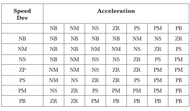
The proposed controller also uses 7 linguistic variables such as: Positive Big (PB), Positive Medium (PM), Positive Small (PS), Zero (ZR), Negative Small (NS), Nega-tive Medium (NM) and NegaNega-tive Big (NB)
The membership functions are chosen to be trapezoidal if the input signal is “PB” or “NB” and triangular or gaussian for the others. The defuzzification of the fuzzy variables into crisp outputs is tested by using the center of gravity (COG) and the Mean of Maxima (MOM) methods.
2.1 Training the Controller
For the rule-base, the relationship between the fuzzy controller inputs and its output can be extracted from the following algorithm:
1. simulate the conventional controller.
2. Save each sample value of (∆ω , change in ∆ω, and Upss) 3. At each sample time t:
∆ω ∈ the class with max membership among (NB,NM,NS,ZR,PS,PM,PB) so at sample time ∆ω is ω_1 ... (a)
change in ∆ω ∈ the class with max membership among (NB,NM,NS, ZR,PS,PM,PB )
so at sample time t , ∆ω is ω_1 ... (b)
This will form the contents of the rule-antecedent (If-part of a rule)
Upss ∈ the class with max membership among (NB,NM,NS,ZR,PS,PM,PB) so at sample time t , Upss is? u_1 ... (c)
The contents of the rule-consequent (then-part of the rule) And a total rule can be formed as:
From (a), (b) and (c): the rule “If ∆ω is ω_1 and change in ∆ω is dω_1 then Upss is u_1”
After generating the rules, the tuning procedures are carried out manually by observation of the control surface relating to the controller. A sample of these rules is shown in Table 1.
Table 1 Rule Extracted from the conventional controller
Speed Acceleration Dev
NB NM NS ZR PS PM PB
NB NB NB NB NB NM NS ZR
NM NB NB NM NM NS ZR PS
NS NB NM NS NS ZR PS PM
ZP NM NM NS ZR ZR PM PM
PS NM NS ZR ZR PS PM PB
PM NS ZR PS PM PM PM PB
PB ZR ZR PM PB PB PB PB
2.2 ANFIS Controller
inference system (FIS) whose membershi p function parameters are adjusted using either a backpropagation algorithm alone, or in a combination with a least squares type of method. This allows the fuzzy systems to learn from the data they are modeling.
For the backpropagation-based NF approach, it includes the Sugeno’s model with the following format:
Ri : if speed deviation error is w and the acceleration is w, then Upss
fx = piw + qi w + ri (1)
where i = (1, n * m) refers to the rule number,
j = (1, n) refers to the Speed Deviation Error terms in the xe fuzzy set, n, mrefers to the number of terms generated,
k = (1, m) refers to the acceleration terms in the fuzzy set, n, m pi, qiri is the ith consequent (PSS output) parameters.
In the ANFIS Editor, the fuzzy inference is generated using two partition methods; grid partitioning and subtractive clustering. For grid partitioning, it uses the Fuzzy C-means clustering (FCM) data clustering technique. FCM is a data clustering algorithm in which each data point belongs to a cluster with a degree specified by a membershi p grade.
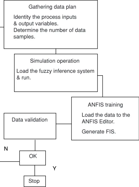
After generating the fuzzy inference, the generated information describing the model’s structure and parameters of both the input and output variables are used in the ANFIS training phase. This information will be fine-tuned by applying the hybrid learning or the backpropagation schemes. The generated model is of a first-order Sugeno’s form and the generated rules in the form described in equation (1). After this stage, the MFs will be adjusted to optimise the controller action (see Figure 1).
The input signals to the ANFIS controller for the PSS are ω and w. The ANFIS controller parameters generated by the ANFIS Editor, based on two inputs and 331 training data points, are as follows:
3.0 SIMULATION RESULTS
The single-line diagram of the two-area, 4-machine test system, as shown in Figure 2, is used to examine both local and inter-area oscillations control problems. This system is created especially for the analysis and study of the inter-area oscillation problem [6].
Figure 1 Anfis Design Procedure for PSS
Figure 2 4 Machine-Two Area System
N
Y Gathering data plan
Identity the process inputs & output variables.
Determine the number of data samples.
Simulation operation
Load the fuzzy inference system & run.
ANFIS training
Load the data to the ANFIS Editor.
Generate FIS. Data validation
OK
Stop
GEN11
GEN2 GEN12
GEN1
967 MW 1767 MW
10 20 3 101 13 120 110
As shown in the above single-line diagram there are four generators, GEN1 and GEN2 for area #1, GEN11 and GEN12 for area #2, and four 20/230 kV step-up transformers. There are two loads in the system at buses 3 and 13. This system exhibits three electromechanical modes of oscillations where one inter-area mode of the generating units in one area oscillates against those in the other area. The fre-quency of this mode varies from 0.35 to 0.75 Hz depending on the operating condi-tions. Two local modes represent oscillations between the generating units within each area. The frequency of the local modes is around 1.3 Hz and the loads are modeled as constant impedances. One set of FLPSS controllers is used for generator number one and one conventional-PSS for generator number two.
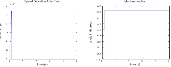
In order to test the robustness of the proposed design procedure of FLPSS, an experiment was carried-out for a three-phase to ground fault at the middle of one transmission line between busses 3 and 13, which is cleared after 0.05 seconds by tri pping the fault-line. A comparison between the results of a lead-lag and fuzzy controllers in the face of different disturbances is presented. The results of the simu-lations can be divided into three parts depending on which controller is used:
(a) For the Conventional Controller. (b) For the Fuzzy Logic Controller. (c) For the ANFIS Controller.
For the conventional controller, a double lead-lag compensator taken from Power System Toolbox (PST 1997) is used.
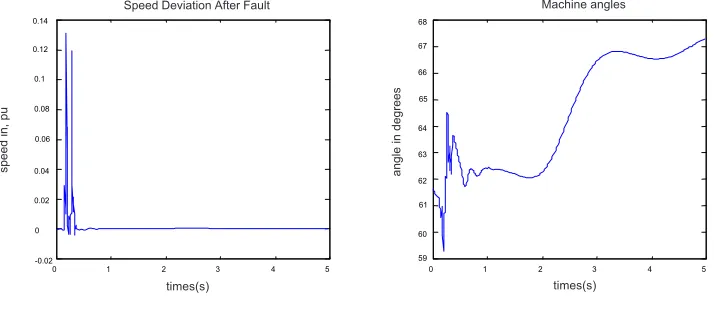
For designing the FLPSS, a Mamdani Type FL is used for both inputs and output with 3 Membership Functions(MF’s), 5 MF’s and 7MF’s and COG and MOM defuzzification methods. The results show that the oscillations are damped more effectively when the FLPSS and the ANFIS are used. From all the results shown in
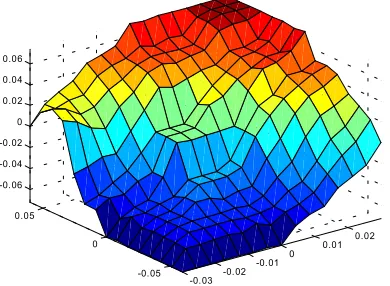
Figure 3 Membershi p Function Control Surface
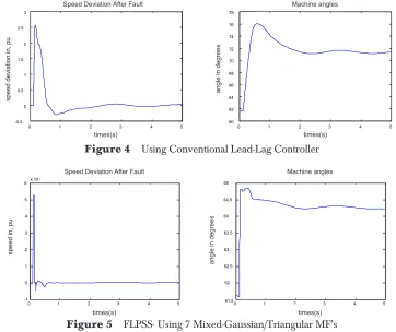
Figure 3 to Figure 9, it can be seen that the mixed-Gaussian/ Triangular MF gives the best results compared with the others. Here best means reaching the steady state condition in the shortest time and with a minimum deviation. By using the MOM defuzzification method, (see in Figure 6), the controller settles at zero as the rules move abruptly from each cell to cell. This is expected since the MOM is more suited for decision making problems.
The control surface for the Mixed-MF is shown in Figure 3. There is a small flat region in the origin to guarantee equilibrium. The small flat region in the origin is followed by sharp slopes in all direction to reflect non-linearity and to provide a quick response from the controller to even small deviations in the speed or accelera-tion of the rotor.
4.0 CONCLUSION
The work in this research involves a fuzzy logic and ANFIS controller, which is built based on the data generated by the conventional controller. The generation of fuzzy rule-based and input-output domain ranges has been investigated. It has been found that the FLPSS provides more robust control against severes disturbances with quicker settling-times when compared with a conventional lead-lag stabilizer.
Figure 4 Using Conventional Lead-Lag Controller
! " # $ $ $ $ $# %&' ! ' '
Figure 5 FLPSS- Using 7 Mixed-Gaussian/Triangular MF’s
speed in, pu
angle in degrees
Speed Deviation After Fault Machine angles
times(s) times(s)
Machine angles Speed Deviation After Fault
angle in degrees
speed deviation in, pu
Figure 6 FLPSS- Using 7 Triangular MF’s with MOM defuzzification
Figure 7 FLPSS- Using 5 Gaussian MF’s
Figure 8 ANFIS - Using 3 MF’s
speed
in,
pu
angle in degrees
Speed Deviation After Fault Machine angles
times(s) times(s)
speed
in,
pu
angle in degrees
Speed Deviation After Fault Machine angles
times(s) times(s) $ # $ # + $ $ # # speed in, pu
angle in degrees
Speed Deviation After Fault Machine angles
ACKNOWLEDGEMENTS
The first author acknowledges financial support for this study from UTM-SLAB, Malaysia.
REFERENCE
[1] Abido, M. A. (1999). ‘A novel Approach to conventional power system stabilizer design using tabu search’, Int. Journal of Eec Power and Energy System. 21(6): 443–454.
[2] Barreiros, JL, Silva A. S., A. J. Simoes Costa (1998) ‘A self-tuning generalized predictive power system stabilizer’ Electric Power & Energy Systems. 20(3): 213–219.
[3] PST. (1997) 'Power System Toolbox for Matlab’ Cherry Tree Scientific Software, Canada.
[4] Hsu, K. Y., C. H. Cheng. (1990) ‘Design of Fuzzy Power System Stabilizer for multimachie power sys-tems', IEE Pt C, May.
[5] Hsu, Y. Y., C. R. Chen. (1991). ‘Tuning of Power System Stabilizer using Artificial Neural Network’
IEEETrans. Energy Convers. 6(4): 616–619.
[6] Kundur, P. (1994) Power System Stability and Control. Mc Graw-Hill Press. [7] Mathwork, Co (1999) Matlab V5.3.
Figure 9 ANFIS- Using 5 MF’s
#
!
"
+ $ #
%&'
! '
'
speed
in,
pu
angle in degrees
Speed Deviation After Fault Machine angles