NIC Controller & Web Interface
24 x7 Installation and Technical Support
1-866-240-6614
Table of Contents
1 OVERVIEW... 3
2 INSTALLATION AND TURN-UP ... 3
3 MINIMUM REQUIREMENTS... 7
3.1 WEBPAGE,TELNET, AND SNMP... 7
3.2 RS232 ... 7 4 INITIAL SETTINGS ... 8 5 IPSETUP... 8 5.1 DIRECT CONNECTION... 9 5.2 LANCONNECTION... 10 5.3 AUTO IPUPDATE... 12 5.4 UPDATE SOFTWARE... 12 6 WEB INTERFACE ... 15 6.1 LOGIN... 15 6.2 HOME PAGE... 16 6.3 MODULES PAGE... 17
6.4 SYSTEM CONFIGURATION PAGE (SYS.CONFIG.) ... 18
6.5 BATTERY MGT... 34 7 TELNET/RS232 ... 35 8 SNMP... 35 8.1 MIBELEMENTS... 35 8.2 SNMPTRAPS... 36 8.3 SNMPTRAP MONITORING... 37
1 Overview
The NIC provides a web (GUI) interface for additional control of the Valere J-series and H-J-series (Mini) power systems. The purpose of this manual is to cover the web interface, Telnet, RS232, and SNMP. This controller will work with 12V, 24V, or 48V output systems.
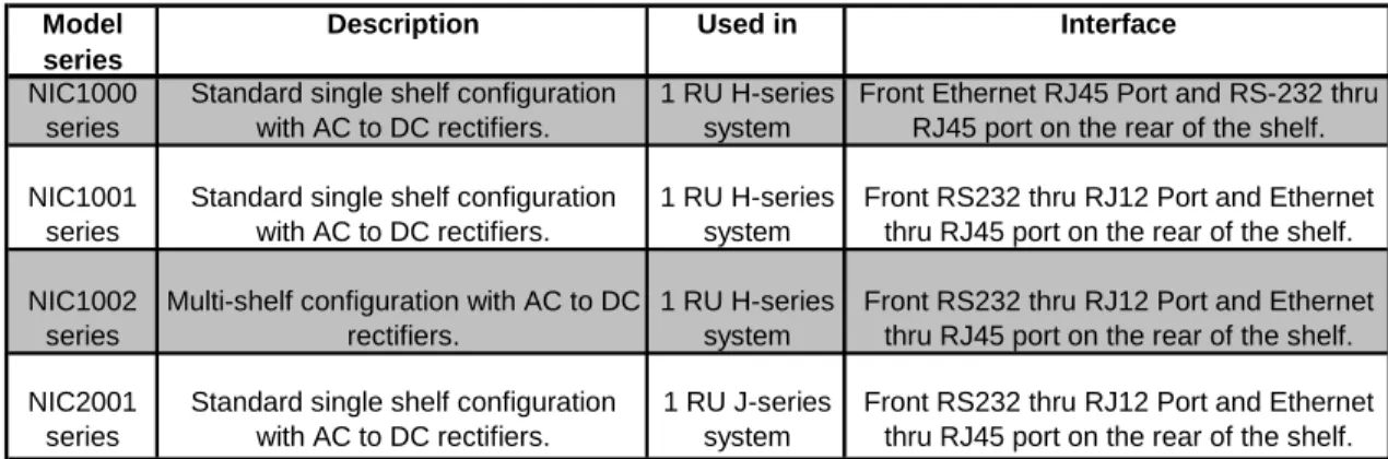
Table 1 provides a list of products that are covered in this manual. In addition, the table provides a description of the products and their uses.
Model series
Description Used in Interface NIC1000
series
Standard single shelf configuration with AC to DC rectifiers.
1 RU H-series system
Front Ethernet RJ45 Port and RS-232 thru RJ45 port on the rear of the shelf.
NIC1001 series
Standard single shelf configuration with AC to DC rectifiers.
1 RU H-series system
Front RS232 thru RJ12 Port and Ethernet thru RJ45 port on the rear of the shelf.
NIC1002 series
Multi-shelf configuration with AC to DC rectifiers.
1 RU H-series system
Front RS232 thru RJ12 Port and Ethernet thru RJ45 port on the rear of the shelf.
NIC2001 series
Standard single shelf configuration with AC to DC rectifiers.
1 RU J-series system
Front RS232 thru RJ12 Port and Ethernet thru RJ45 port on the rear of the shelf.
Table 1 - Available Controllers
2 Installation and Turn-up
See the respective shelf installation & maintenance manual for controller slot location. The controller is hot-swappable, therefore the controller can be removed or installed while the system is operating without any interruption. In the event of a controller removal, the system will remain at the last known settings until a new controller is installed.
The controller will arrive already setup with the default settings based on the profile number. No setup is required. The values in Table 2 are based on the Valere default controller with profile number 01 (PN 01). Your profile number may be different and can be determined from the part number of the NIC. For example, using the part number NIC1000-A01-10, the second and third digits in the second section (in case 01) is the controller profile number. Contact Valere tech support at 1-866-240-6614 for a copy of your company’s controller settings if different from profile # 01.
NOTE: The rectifiers will change to the new controller settings upon installation. Any settings changed from the defaults will have to be reset.
System Parameters Description 12 Volt Nominal 24 Volt Nominal 48 Volt Nominal Plant Settings Float Voltage
The voltage to which the rectifiers will regulate the plant voltage during float
mode (Volts) 12 Vdc 27 Vdc 54 Vdc
High Voltage Shutdown
The NIC will shut down the rectifiers if the plant voltage exceeds this set point.
(Volts) 14 Vdc 29 Vdc 58 Vdc
System Current Limit Enables the system current limit feature Disabled Disabled Disabled
Current per Rectifier
The NIC will limit the current of the
rectifiers to this value (Amps) 220 A 220 A 220 A
Language The language the webpage is displayed. English English English
Alarm Settings
High Voltage Alarm
The NIC will issue a High Voltage Alarm if the plant voltage exceeds this set point
(Volts) 13 Vdc 28.25 Vdc 57 Vdc
Battery on Discharge
The NIC will issue a Battery-On-Discharge alarm if the plant voltage falls below this
set point (Volts) 11 Vdc 24 Vdc 48 Vdc
Low Voltage Alarm
The controller will issue a Low Voltage Alarm if the plant voltage falls below this
set point (Volts) 10 Vdc 22 Vdc 44 Vdc
Battery Boost Settings Boost Voltage
The voltage at which the equalize / boost
charge will begin (Volts) 13 Vdc 28 Vdc 56.5 Vdc
Boost Duration
Duration of time the equalize/boost charge
is active (H:M:S) 12:00:00 12:00:00 12:00:00
Boost Stop Current
The lower limit at which the boost test will stop. 0 = disabled. Requires battery
shunt (Amps) 0 A 0 A 0 A
Battery Boost Start Modes Manual Mode
Enables or disables the manual boost
mode feature Disabled Disabled Disabled
Periodic Mode
Enables or disables automatic boost mode that runs a boost test every x number of
days Disabled Disabled Disabled
Period
The number of days in between periodic
boost tests 30 days 30 days 30 days
Time of Day
The time of day the periodic boost mode
will start (H:M:S). 24 hour format 8:00:00 8:00:00 8:00:00
Auto Current Mode
Enables or disables the current based autoboost test. When enabled the boost feature will automatically start if the start
current value is exceeded Disabled Disabled Disabled
Current Delay
The amount of time the start current must be exceeded before the test will start.
(Minutes) 5 minutes 5 minutes 5 minutes
Start Current
The value at which the current autoboost
test will start. (Amps) 100 Amps 100 Amps 100 Amps
AC Fail Mode
Enables or disables the AC fail based autoboost test. When enabled the boost feature will automatically start if an AC failure lasted longer than the AC fail
duration Disabled Disabled Disabled
AC Fail Duration
The length of time (H:M:S) the AC failure
System Parameters Description 12 Volt Nominal 24 Volt Nominal 48 Volt Nominal DC Drop Voltage
The voltage the batteries must drop below during the AC failure to trigger the
autoboost feature (Volts) 10 Vdc 22 Vdc 44 Vdc
Battery Recharge Current
Limit*
Batt. Recharge I Limit*
Enables or disables the battery current
limit feature. Disabled Disabled Disabled
Current Limit*
The maximum current the system will
allow through the battery shunt 600 amps 600 amps 600 amps
Battery Discharge Test Duration
Sets the length of time (H:M:S) that the
battery discharge test will run. 1:00:00 1:00:00 0:30:00
Alarm Voltage
Sets the voltage at which an alarm will be generated if the battery voltage falls below
it during the Battery Discharge Test. 10.5 Vdc 21.5 V 42 V
Abort Voltage
The voltage at which the battery discharge test will abort at when the system voltage
drop below this point. 10.5 Vdc 21.5V 42 V
Thermal Comp Adjust
Enabling this value will take thermal compensation effects into account during the test. Disabling this value will disable Thermal Compensation effects during the test. Both Thermal Compensation, and T Comp BDT have to be Enabled for thermal comp. effects to take place during
BDT. Disabled Disabled Disabled
BDT Start Modes
Manual Mode
Enables or disables the manual battery
discharge mode feature Disabled Disabled Disabled
Schedule Enable
Enables or disables the schedule battery
discharge mode feature Disabled Disabled Disabled
Temperature Compensation
Thermal Compensation
Enables thermal compensation. Thermal compensation adjusts the float voltage of the rectifiers to increase or decrease the
temperature of the batteries. Disabled Disabled Disabled
Thermal Comp Sense
Selects temperature sensing device to use for battery temperature compensation; Internal sensor or External temp probes. The controller will autosense when external probe is attached and
automatically adjusts value to external. External External External
Temperature Units
Selects the units the temperature readings
are given in. Either Celsius or Fahrenheit Celsius Celsius Celsius
T Comp Boost
The feature will allow the controller to activate the boost feature during a thermal
compensation Disabled Disabled Disabled
High Start Temp
The high temperature at which the
controller activates thermal compensation 35 °C 35 °C 35 °C
High Slope
The slope value at which the controller will reduce the float voltage per degree if
System Parameters Description 12 Volt Nominal 24 Volt Nominal 48 Volt Nominal
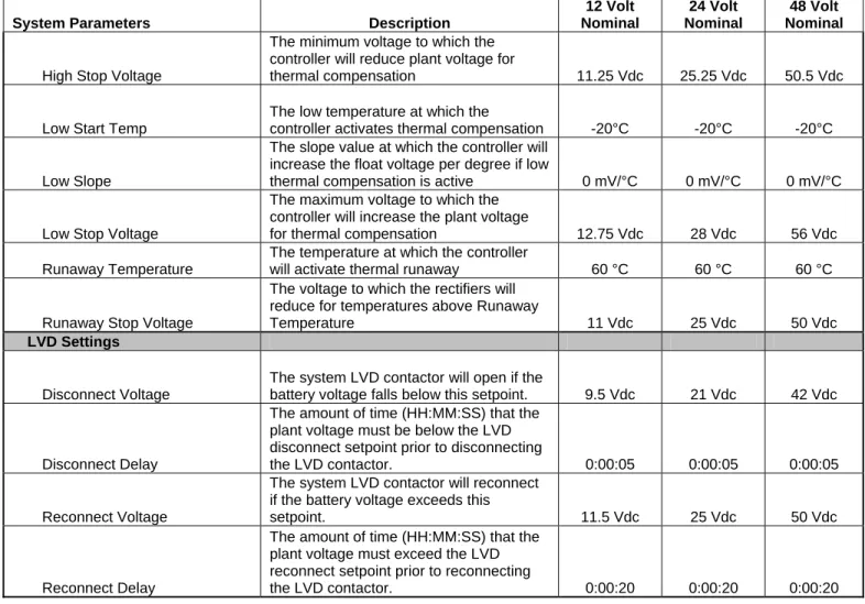
High Stop Voltage
The minimum voltage to which the controller will reduce plant voltage for
thermal compensation 11.25 Vdc 25.25 Vdc 50.5 Vdc
Low Start Temp
The low temperature at which the
controller activates thermal compensation -20°C -20°C -20°C
Low Slope
The slope value at which the controller will increase the float voltage per degree if low
thermal compensation is active 0 mV/°C 0 mV/°C 0 mV/°C
Low Stop Voltage
The maximum voltage to which the controller will increase the plant voltage
for thermal compensation 12.75 Vdc 28 Vdc 56 Vdc
Runaway Temperature
The temperature at which the controller
will activate thermal runaway 60 °C 60 °C 60 °C
Runaway Stop Voltage
The voltage to which the rectifiers will reduce for temperatures above Runaway
Temperature 11 Vdc 25 Vdc 50 Vdc
LVD Settings
Disconnect Voltage
The system LVD contactor will open if the
battery voltage falls below this setpoint. 9.5 Vdc 21 Vdc 42 Vdc
Disconnect Delay
The amount of time (HH:MM:SS) that the plant voltage must be below the LVD disconnect setpoint prior to disconnecting
the LVD contactor. 0:00:05 0:00:05 0:00:05
Reconnect Voltage
The system LVD contactor will reconnect if the battery voltage exceeds this
setpoint. 11.5 Vdc 25 Vdc 50 Vdc
Reconnect Delay
The amount of time (HH:MM:SS) that the plant voltage must exceed the LVD reconnect setpoint prior to reconnecting
the LVD contactor. 0:00:20 0:00:20 0:00:20
3 Minimum Requirements
3.1 Webpage, Telnet, and SNMP
• An Ethernet, Cat-5 crossover patch cord (not provided) with RJ-45 connectors is required for a direct connection between a computer and the Valere Power LAN port.
• An Ethernet, Cat-5 straight through patch cord (not provided) with RJ-45 connectors is required for the LAN connection.
3.2 RS232
• Cable CA210042487 (sold separately) is required to connect to the RJ12 connection on the front of the NIC1001 and NIC2001. The pin out for this connection is shown below.
1 6
Figure 1 – Front communication port
Pin Description 1 GND 2 RX 3 NC 4 NC 5 TX 6 GND
Table 3 – Front RS232 Pin Out • The pin out for the RS232 connection for the NIC1000 on the rear
RJ45 connection is shown below.
1 8
Figure 2 - Rear communication port
Pin Description 1 TX 2 GND 3 RX 4 NC 5 NC 6 GND 7 NC 8 NC
4 Initial Settings
Ensure that any firewall programs or pop up blockers are set to allow traffic from the program IPSetup.exe via UDP packets (uses port # 20034). Also, disable any wireless networks being used as they interfere with the communication with the controller.
The default LAN setting on the Valere Power system is DHCP enabled. The IP address will have a default value of 0.0.0.0.
Every NIC controller is shipped from Valere Power with its own unique MAC address. This unique identifier is a hardware address that uniquely identifies each node (Valere Power System) of a network.
5 IPSetup
There is an application (IPSetup.exe) that comes with every LAN enabled Valere Power system on the CD provided with the NIC.
Figure 3 – IPSetup
The IPSetup application gives access to the network management settings for the LAN Port and access to the web interface. The web interface feature displays the power plant status and many other remote features shown in the web interface section (section 6).
Running IPSetup will interrogate the LAN (Local Area Network) or direct connection between a PC and the Valere Power LAN Port and only identify Valere Power Systems that are LAN enabled.
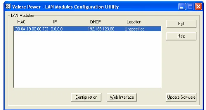
The first dialog box that will appear when IPSetup is executed is the LAN
Modules Configuration Utility window as seen in Figure 4. From this window you will find the MAC address, IP address, DHCP address, Location and network management tools for the Valere Power Systems.
Note: Before using IPSetup make sure that all firewalls are set to accept the IPSetup.exe program and UDP packets on port # 20034.
Note: IPSetup is a self executable file and does not require any installation. The program can be run from the CD or copied to a hard drive and an run from there.
Figure 4 – LAN Modules Configuration Utility 5.1 Direct Connection
If you are establishing a direct connection between the Valere Power System and a PC, be sure you are using a crossover patch cord. Keep in mind the IP address will always have a default address of zero when first shipped from factory.
Selecting a MAC address & clicking on the Web Interface button will
establish a direct connection between that Valere Power System and the PC. For the default IP address of zero, the power system will initiate an automatic IP update in order to establish a connection.
By selecting the “Yes” button in the message as seen in Figure 5, you will initiate the automatic IP update. This will establish an IP address with the Valere Power System and begin the process of launching the Web Interface application. Once a connection is established, move to section 6.
Figure 5 – Auto IP Update
Note: If the power system has already been assigned an IP address from a previous session or installation then the automatic IP update will
not run (since it is not needed) and a direct connection will be establish through the web. If this is the case, then you can move forward to section 6.
Note: Once you have terminated a direct connection and you are going to be installing the power system onto a DHCP configured network or a network using static IP address, you will need to go back to the LAN Modules Configuration Utility window and enabled DHCP or assign an IP address to the LAN card. See section 5.2 for details.
5.2 LAN Connection
If the Valere Power System is being installed directly onto a LAN, then you will need to determine if the LAN is a DHCP configured network or if a static IP address is required.
If this is a new installation that is being placed on a DHCP configured network, then the Valere Power System is ready for installation since it is already DHCP enabled. If a Static IP address is required then please proceed to section 5.2.2 for enabling a static IP address.
Referencing Figure 4, the LAN Modules Configuration Utility:
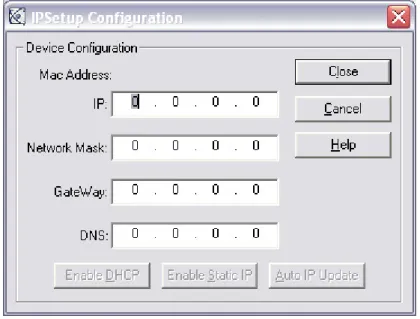
Select the appropriate Valere Power System (by identifying the MAC address or LAN Port IP address) and click the “Configuration” button. This will open the LAN Interface network settings window as seen in Figure 6.
From this window you will be able to choose the following options:
• Enabled DHCP – allows the controller to work on a DHCP network
• Enabled Static IP – allows the controller to work on a static IP network
• Auto IP Update – automatically updates the IP address for a direct connection
Figure 6 – IPSetup Configuration
5.2.1 Enabling DHCP
Enabling DHCP allows you to set the power system to dynamically obtain an IP address via DHCP instead of using a static IP address. Enable DHCP is only available if you have previously assigned the LAN card an IP address through Static IP Enable or Auto IP Update.
Once selected, DHCP will be enabled and an address of 0.0.0.0 will be assigned. When executed properly you will be returned to the LAN Modules Configuration Utility window and an IP address of 0.0.0.0 will be returned as seen in the image above Figure 6. The dynamically assigned IP address will also be displayed under the DHCP heading. This will ready the Valere Power System for installation onto DHCP configured network.
5.2.2 Enabling Static IP
Networks that require a static IP address can be assigned using the Enable Static IP button as shown in Figure 7.
Enable Static IP is only available if you have previously assigned the LAN card an IP address through DHCP (default).
Note: IP address used in Figure 6 is for example only, your system administrator will provide you with a proper IP address.
Figure 7 – Assigned IP Address
Move the cursor over the IP address field for editing. Enter the desired IP address, Network Mark, Gateway, and DNS and click the Enabled Static IP button as shown in Figure 7. After enabling the Static IP address, the update window will appear asking you to confirm the IP configuration change. When the Static IP address has been assigned properly you will be returned to the LAN Modules Configuration Utility window and the Static IP address that was assigned to the LAN card will be displayed under the IP heading as seen in Figure 4.
5.3 Auto IP Update
This option is only used when a direct connection between a PC and the Valere Power System is to be established. Auto IP Update will assign an IP address that is compatible with the PC that is establishing the direct
connection. You will not be able to run this option when the Valere Power System is already connected to an existing LAN with more than one LAN module present.
When the IP address has been assigned properly you will be returned to the LAN Modules Configuration Utility window and the IP address that was assigned to the Power System will be displayed under the IP heading.
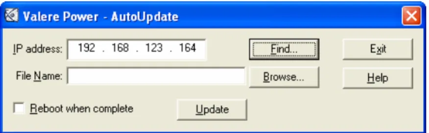
5.4 Update Software
The update software button allows you to remotely upgrade the LAN software so that you may update to the most recent software version available for the Valere Power System.
The update software screen will use the IP address selected when pressing the option.
Figure 8 – Auto Update
Select the appropriate file to load. Please note the only valid file types are “.s19”. Use the “Browse” button to locate the correct update file. Updates are available from Valere Power technical support.
Select whether or not an immediate reboot of the LAN module is desired. The new software load will only take affect after a LAN module reboot so if it is desired to leave the system running “as is” until a later time when the controller can be reset, leave this box unchecked. Press “Update”. A password is needed for the update process to be complete.
• User Name – Admin
• Password – 5001 (unless the password has been changed)
Enter authentication information in the appropriate dialog as shown in Figure 9.
Figure 9 - Authentication
Monitor the progress through the Update Status dialog window shown in Figure 10. Once the upload is complete you will receive a confirmation notice as seen in Figure 11.
Figure 11 – Confirmation Notice
IMPORTANT! If you want the new firmware to be immediately invoked after uploading, be sure to check the “Reboot when complete” button.
The error messages shown in Figure 12 and Figure 13 may appear during the upload procedure if communication is lost or other problems occur. If these problems reoccur please call Valere Power Tech Support.
Figure 12 – Timeout Failed
6 Web Interface
6.1 Login
Once you access the system you will be challenged for authentication as seen in Figure 14. Web communication uses port # 22096 by default.
Figure 14 – Authentication Process
The factory default settings for the authentication process are as follows:
• Administrator privileges, this allows the user to access and change all system settings.
User name: Admin Password: 5001
• User privileges, this allows the user to view system settings and review the system performance only. No changes to the system settings can be made.
User name: User Password: 1001
Passwords are changed from the System Configuration page. Refer to section 6.4.4 for details.
Note: Once you have established Administrator privileges, it is recommended that you change the Admin password for security purposes. Please note that the username and password are case sensitive.
6.2 Home Page
After a successful authentication, the web interface Main Page, as seen in Figure 15, will report the immediate system status of the power plant.
Figure 15 – Home Page
6.2.1 System Status
This area contains the current system status. It includes:
• System Location – User defined name for the controller. The default name is Unspecified
• System Type – 12V, 24V, or 48V Plant depending on the rectifiers/converters installed
• System Voltage – the DC output voltage of the system
• System Current – the DC output current, not including the current through the battery shunt if one is installed (not all system are available with a shunt)
• Battery Current – the amount of current flowing through the battery shunt if one is installed (will not be visible if shunt is not installed)
6.2.2 Thermal Probes/Enclosure Inputs
• Controller Temperature – the temperature value measured by the temperature sensor located inside the controller
• TComp Temperature – the temperature value being used to determine thermal compensation status
• Probe 1, 2, 3, or 4 Status – The battery temperature probe readings. Valid readings include disabled, a temperature value, or removed if a thermal probe has been inserted and removed from the temperature port.
6.2.3 Alarms
The system state has three different states that can be displayed. Factors such as the refresh rate, delays caused by cable lengths, or communication functions may not capture change of state. For example, if you pull out a rectifier and put it back in the shelf faster than the refresh rate, you will not see a “Change” in the system state using the Web Interface.
• Normal: No faults or alarms
• Change: Active when a shelf component such as a rectifier has been removed
• Alarm: Active when an alarm condition exists. See section 6.4.5 for information on alarms
6.2.4 Eventlog
Click on the eventlog button to open the event history in a separate webpage. The eventlog will show the time, date, and the event.
6.3 Modules Page
The modules page, shown in Figure 16, will display the current state of each rectifier and Enclosure1 (if applicable). Enclosure1 can consist of a combination of an LVD and/or TRIO board.
Figure 16 – Modules Page 6.4 System Configuration Page ( Sys. Config.)
The system configuration page, Figure 17, provides access to all system settings.
If the system user has entered the web interface as an “Admin”, then all system settings can be reviewed and modified from this page. If the user has entered as a “User”, then the system configuration may only be reviewed.
6.4.1 Making Changes
To change the system configuration, edit the appropriate fields and click the “Apply” button.
6.4.2 System
The system page allows an administrative user to change system settings from the webpage.
Figure 17 – System Page 6.4.2.1 Plant Setting
The plant configuration tab contains most of the major system settings for the power system including the following.
• Float Voltage – DC voltage which the rectifiers will output
• High Voltage Shutdown – the DC voltage at which the rectifier(s) will shutdown if exceeded.
• System Current Limit status – Enables or disables the rectifier current limit feature
• Current per Rectifier – allows the user to set a limit, below the maximum capacity of the rectifier, on the amount of current each rectifier will output
• Language – Language the webpage is displayed (English, Francais, Espanol, Deutsch). You must logout and log back in for language to change. Currently only Spanish is available.
6.4.2.2 Alarm Settings
The alarm settings tab contains all the major alarm settings for the power system including the following.
• High Voltage Alarm – The voltage at which the controller will trigger an alarm if the system voltage exceeds it
• Battery on Discharge – The voltage at which the battery on discharge alarm will trigger. This is your first warning that the batteries voltage is dropping to low levels
• Low Voltage Alarm – The voltage at which the controller will trigger a low voltage warning. This is your final warning that the battery voltage is at a dangerously low level
6.4.2.3 Hardware Test
• Lamptest – Click to light all LED’s on rectifiers
6.4.2.4 Presets
The three Presets are nonadjustable values from the factory. For profile number 01 (Valere default) all presets are the same. Select the desired preset in the drop down menu and press the Set Preset button.
6.4.2.5 LVD Settings
This section is only visible if an LVD is installed in the system. Not all systems are available with an LVD. See your respective shelf installation and operation manual for identifying a system with an LVD.
• Selected Contactor – the contactor being setup with the set points below. Contactors available include battery, load 1, load 2, and load 3. See shelf installation and maintenance manual for LVD type.
• Disconnect Voltage – the voltage at which the LVD contactor will open and disconnect the batteries
• Disconnect Delay – the amount of time (H:M:S) the system battery voltage must be below the disconnect voltage to open the contactor
• Reconnect Voltage – the voltage at which the LVD contactor will close and reconnect the batteries
• Reconnect Delay – the amount of time (H:M:S) the system battery voltage must be above the reconnect voltage to close the contactor
6.4.2.6 Temperature Control
This section is only visible if a TRIO is installed in the system. Not all systems are available with a TRIO. See your respective shelf installation and operation manual for identifying a TRIO card.
The purpose of the temperature control is to allow the user to activate and deactivate a form-C relay based on a temperature value. For example, an exhaust fan could be activated when the temperature exceeded a
specified value; once the temperature falls below the recover temperature the relay would de-energize and turn off the fan.
Note: This feature gives the user advanced functionality of the alarm output relays. The alarm relay chosen for temperature control will lose normal alarm functionality when chosen as the output relay. Therefore Valere recommends using caution when using this feature.
• Select Configuration – Allows the user to setup 12 control configurations.
• Input Module – specifies the TRIO used for input probe (Enclosure: 1, Module: 1)
• Input Probe – specifies which temperature probe is used for the input temperature
• Trigger Temperature – the temperature value at which the selected output relay energizes
• Recover Temperature – temperature value at which the selected output relay de-energizes
• Output Module – specifies the TRIO used for the output relay
6.4.3 Batteries
The batteries page allows an administrative user to change battery management settings.
6.4.3.1 Battery Boost Settings
Boost test is a feature that will increase the output voltage of the
rectifier(s) to boost charge your batteries or equalize your battery’s cell voltages. The battery boost settings section contains all the variables to setup, adjust and a run battery boost test. The battery boost settings include the following.
• Boost Voltage – the voltage to which the output voltage will increase when the feature is activated
• Boost Duration – the length of time the boost charge will last
• Boost Stop Current – the value, that if exceeded, the boost charge will abort and the system will return to it normal output voltage. This is a safety measure to prevent the batteries from drawing too much current
• Boost Status – current status of battery boost test (active or inactive)
• Result – outcome of the most recent test (stopped, aborted, complete)
• Runtime – the actual length of time the most recent test lasted (HH:MM:SS)
• Start/Stop – Click to start or stop a manual boost. Manual mode must be enabled.
6.4.3.2 Battery Boost Start Modes
This feature allows the battery boost test to start manually or automatically. The battery boost start modes are as follows.
• Manual Mode – enables or disables the user started boost mode
• Periodic Mode – enables or disables the periodic boost mode. Allows the user to automatically run a test every certain number of days at a specified time of the day. For example, every 30 days at 8:00:00 (on a 24 hour clock)
• Auto Current Mode – enables or disables the current (amps) based boost mode. Allows the user to set a battery current value at which the boost charge will begin. For example, if the battery current were to exceed a start current value of 40 amps the boost charge would begin. A battery shunt is required to activate this feature
• Current Delay – a user defined delay in minutes that the battery current must exceed the start current value before beginning the boost charge. For example, if the battery current were to exceed the start current value of 40 amps for more than 10 minutes the auto current boost charge would activate
• Start Current – the current value (amps) at which the auto current boost charge will activate
• AC Fail Mode – enables or disables the feature to start a boost charge after an AC failure. For example, if the battery voltage falls below the DC drop voltage value of 44 volts for more than the duration value of 15 minutes the boost charge will activate
• Duration – the length of time the battery voltage must be below the DC drop voltage value for the AC fail boost charge to activate
(HH:MM:SS)
• DC Drop Voltage – the value the battery voltage must fall below during an AC failure for the AC fail boost charge to activate
6.4.3.3 Battery Recharge Current Limit
This feature sets a maximum amount of current allowed to pass through the battery shunt. This feature requires a battery shunt to be installed in the system to be visible.
• Batt. Recharge I Limit – enables or disables the battery recharge current limit
• Current Limit – the maximum amount of current allowed to pass through the battery shunt
6.4.3.4 Battery Discharge Test
This feature allows the user to test the health of their batteries while
keeping the rectifiers in a “suspended” state as a backup in case of battery failure. The test can be started manually or automatically based on a scheduled time.
• Duration – the length of time of the test (HH:MM:SS)
• Alarm Voltage – the user set voltage that the batteries should not fall below for the duration of the test. If the batteries do fall below this value the test will fail but continue to run the duration of the test. A battery discharge test failure alarm will be created.
• Abort Voltage – the user set voltage that the test will stop running, even if not complete.
• Thermal Comp Adjust – this feature, when enabled, will
automatically adjust the Alarm Voltage to prevent an invalid alarm do to thermal compensation. (enabled or disabled)
• Status – the current state of the test. (active or inactive)
• Result – the results of the most recent test (cleared, pass, failed, stopped, aborted, or in progress)
• Runtime – the duration of the test (HH:MM:SS)
• Start/Stop – Click to start or stop a manual battery test. Manual mode must be enabled.
6.4.3.5 BDT Start Modes
This feature allows the battery discharge test to start manually or automatically. The battery discharge test start modes are as follows.
• Manual Mode – enables or disables the user started test mode
• Schedules – Allows the user to setup 12 different time schedules to run automatic battery discharge tests
• Enable – allows the user to enable or disable the “Scheduled” battery discharge test(s)
• Month – the month the test will be automatically started
• Day – the day of the month the test will be automatically started
• Time of Day – the time of the day the test will be automatically started (HH:MM on a 24hr clock)
6.4.3.6 Thermal Compensation
This feature will increase (Low thermal compensation) or decrease (high thermal compensation) the float voltage of the rectifier if your battery temperature exceeds a set limit. This feature is an automatically executed feature that will also automatically turn off once a satisfactory temperature has been reached.
• Thermal Compensation – enables or disables thermal compensation
• Thermal Comp Sense – determines which thermal sensor will be used to activate thermal compensation (internal or external).
• Temperature Units – the unit of measurement used (°F or °C)
• T Comp Boost – if enabled, allows the Boost feature to activate during an active thermal compensation state
• High Start Temp – the temperature value which, if exceeded, will activate thermal compensation
• High Slope – the voltage the controller will reduce the plant voltage by every degree over the High Start Temp value
• High Stop Voltage – the lowest voltage value the controller will allow while thermal compensation is active
• Low Start Temp – the temperature value which, if the temperature falls below, will activate low thermal compensation
• Low Slope – the voltage the controller will increase the plant voltage by every degree under the Low Start Temp value
• Low Stop Voltage – the highest voltage value the controller will allow while low thermal compensation is active
• Runaway Temperature – the temperature value which, if exceeded, will drop the rectifier output voltage to the Runaway Stop Voltage
• Runaway Stop Voltage – the voltage value that the rectifier output will fall to when the Runaway Temperature value is exceeded
6.4.4 Network
This section allows the user to setup password protections and adjust SNMP settings for network communication.
Figure 19 – Network 6.4.4.1 SNMP Settings
This section allows the user to change SNMP addresses and webpage passwords.
• Trap Address 1 – the user defined IP address to which SNMP traps are sent
• Trap Address 2 – the user defined second IP address to which SNMP traps are sent
• Trap Address 3 – the user defined third IP address to which SNMP traps are sent
• Trap Address 4 – the fourth IP address to which SNMP traps are sent
• SNMP Read Password – enter password required for user’s SNMP program to be able to read SNMP traps (up to 8 characters)
• SNMP Write Password – enter password required for user’s SNMP program to be able to write SNMP traps (up to 8 characters)
• SNMP Trap Password – enter password required for user’s SNMP program to be able to send SNMP traps (up to 8 characters)
• SNMP Heartbeat – enables or disables the SNMP heartbeat feature. This feature will send a “heartbeat” at the set interval to notify the user that the NIC is still operating
• Heartbeat Interval – the time value between SNMP heartbeats (seconds)
6.4.4.2 Ethernet Settings
This section allows the user to provide a name for the NIC and set the web socket port number.
• System Identification – a 20 character ID that the user can use to identify controllers on a network
• Web Socket Port # - the port number the controller uses for Web interface communication. Default port number is 22096.
6.4.4.3 Security
This section allows the user to change the security passwords required to log onto the NIC.
Note: For the NIC2001-series controller passwords can consist of all characters except semi-colon (‘;’), comma (‘,’), and period (‘.’).
Note: For the NIC100x-series controller passwords can consist of only alpha-numeric characters.
• Admin Password – the password for the Admin (administrator) login (up to 8 characters)
• User Password – the password for the User login (up to 8 characters)
• Admin Front Panel PIN – not applicable for systems without a display
6.4.5 Office Alarms
This section allows the user to set the severity (major or minor) of all alarms for the Valere Power system. The audible alarm will not work with the NIC controller.
Below is a list of potential system alarms:
• Select Configuration - allows the user to select the (Enclosure 1 TRIO) and map the four form-C relays accordingly. If left at System Mask Set or if no “TRIO” is installed this section allows the user to set the severity of the system alarms
• Major Alarm – allows the user to enable the audible alarm for major alarms
• Minor Alarm – allows the user to enable the audible alarm for minor alarms
• AC Fail Alarm – loss of commercial AC power
• High Voltage Warning Alarm – the system voltage has exceeded the high voltage setting
• High Voltage Shutdown Alarm – the controller has shut the
rectifiers down because the rectifier voltage has exceeded the HVSD setting
• Battery On Discharge Alarm – the battery voltage has dropped below the battery on discharge setting
• Low Voltage Warning Alarm – the battery voltage has dropped below the LVD Warning setting. This value will be less than the battery on discharge setting
• LVD Open Alarm (Requires LVD to be installed) – the low voltage disconnect has opened because the battery voltage has dropped below the LVD Open setting
• Distribution Alarm – a fuse or circuit breaker is in the open state
• Enclosure Alarm – an alarm has triggered on one of the auxiliary input alarm ports. Requires probe input to be set to Enclosure
• System Redundant Capacity Alarm – the system current has extended N+1 redundancy
• Rectifier Current Share Alarm – one or more rectifiers is not sharing the system current within tolerances
• Single Rectifier Fail Alarm – one rectifier has stopped outputting power
• Multiple Rectifier Fail Alarm – more than one rectifier has stopped outputting power
• System Communication Alarm – the controller has lost communication with a rectifier or converter
• System Over Temperature Alarm – the maximum temperature setting has been exceeded. See section 6.4.2.1.
• Thermal Runaway - the batteries have exceeded the thermal runaway setting. See section 6.4.3.6.
• Battery Discharge Test Fail – the battery voltage has dropped below the BD alarm setting during a battery discharge test. See section 6.4.3.3.
• Ringer B Alarm – Ringer B has failed (not applicable to this system)
• Single Ringer Fail Alarm – one ringer has stopped outputting power (not applicable to this system)
• Multiple Ringer Fail Alarm – more than on ringer has stopped outputting power (not applicable to this system)
• Temperature Probe Alarm – one of the temperature probes has been removed (requires TRIO)
• Ringer Comm. Fail Alarm (Requires ringer to be installed) – lost communication with ringer (not applicable to this system)
• Distribution Comm. Fail Alarm – the controller has lost
communication with LVD or distribution card (not applicable to this system)
• Single Converter Fail Alarm – a single converter has stopped outputting power
• Multiple Converter Fail Alarm – more than one converter has stopped outputting power
• Unmapped Address Alarm – a rectifier, converter, LVD or distribution card did not get mapped
• Configuration Error Alarm – If a hardware configuration has been changed
• Display Needs Firmware Alarm – display needs firmware load
• Converter Input Fail Alarm – converter has failed or dc input power is not present
• Batt. Recharge Current Limit Fail – battery recharge current limit has been exceeded.
6.4.6 Alarm Configuration
This menu is only visible if a TRIO is installed. See installation, operation manual of the shelf for physical connection. Not all systems are available with the optional TRIO. This feature is also not available with the controller in Autonomous mode (section 6.4.7.3).
This section allows the user to map any alarm to an alarm relay output. Alarm Configuration can be accessed by clicking on Alarm Mask Set 1 under Select Configuration and Enclosure:1, Module: 1 under Select TRIO. To associate one of the alarms above with a form-C output relay, click on the desired relay for each alarm. Multiple alarms can be associated with a single relay and a single alarm can be associated with multiple relays. Figure 21 shows the default (for profile # 01) alarm configuration for a system with a NIC and a TRIO. For alarm configuration of a system running in autonomous (section 6.4.7.3 on page 33) mode see the corresponding shelf installation, operation manual.
6.4.7 I/O Setup
This section allows the user to setup temperature probes and output alarms for a TRIO if installed. This menu is only visible if a TRIO is installed. See installation, operation manual of the shelf for physical connection. Not all systems are available with the optional TRIO.
Figure 22 – I/O Setup 6.4.7.1 TRIO Configuration
You can select which enclosure and module you would like to configure in this setup
• Select Module – select which enclosure and module you would like to configure. For instance, Enclosure:1 Module: 1 which corresponds to the TRIO.
6.4.7.2 Temperature Probe Configuration
This section allows the user to set the name (10 character limit) and type of input desired for the temperature probe inputs of the TRIO.
• Disabled – probe input is turned off. If a temperature probe is installed the NIC will automatically readjust the setpoint to work as a temperature probe.
• Temperature probe – the probe input is set to operate as a temperature input. If a Valere temperature probe is inserted this setting will be automatically set.
• Enclosure NO – enclosure refers to an external bay alarm that does not apply for these systems.
• Enclosure NC - enclosure refers to an external bay alarm that does not apply for these systems.
• Distribution NO – Use this designation for external, normally open distribution panel alarms, such as fuse fail or circuit breaker tripped.
• Distribution NC - Use this designation for external, normally closed distribution panel alarms, such as fuse fail or circuit breaker tripped.
• Reset Input Names – clicking this button will return all input names back to their default values
6.4.7.3 Relay Configuration
This section allows the user to define an output relay name, type, polarity, and real time status. These features are not available in Autonomous mode.
Note: The relay configuration section gives the user advanced options for configuring the form-C output relays. These options allow the user to change the functionality of the relays. Therefore, Valere recommends that caution be used when using these options.
• Relay Name – for identification purposes only; character limit of 16; for information on alarm association to relays see Office Alarms section.
• Type – sets what the alarm relays will do when they are manually activated by the Status (Realtime) buttons. Type can be either be set to “on/off” in which the relay can be triggered on and then triggered off or set to “pulse” in which the relay will trigger for a set period of time (Pulse Width) and then turn off. Pulse width can be set just below the Type section.
• Polarity – value can be set to either Normally Energized or Normally De-energized. This can be used to change the output polarity of the relay. For example, a normally open relay set to Normally
• Reset Relay Names – clicking this button will return all input names back to their default values
• Status (Realtime) – click “Status (Realtime)” to change the state of the corresponding alarm. This feature does not require clicking on the Apply button to function
• Pulse Width – the amount of time the relay will be triggered when the Status (Realtime) buttons are activated and Type is set to pulse
• Autonomous – sets the TRIO into a mode to operate without a NIC
6.5 Battery MGT
The battery management tab allows the user to run a battery discharge test. In this section, the user can also view current and past tests (up to 8 tests are stored on the controller) on a graphical display. See section 6.4.3.3 and 6.4.3.5 for more information on the battery discharge test setpoints.
7 Telnet/RS232
Telnet is available on the NIC and can be accessed using any Telnet program. Telnet is accessed through the LAN port and the IP address of the controller must be known.
An RS232 connection can be established using any VT100 capable program. Hardware settings:
• 57600 bits per second
• Data bits, polarity none
• Stop bits 1
• Flow control none
Use “get help” for a list of usable commands 8 SNMP
Short for Simple Network Management Protocol, a set of protocols for managing complex networks. The first versions of SNMP were developed in the early 80s. SNMP works by sending messages, called protocol data units (PDUs), to different parts of a network. SNMP-compliant devices, called agents, store data about themselves in Management Information Bases (MIBs) and return this data to the SNMP requesters.
The Valere Power System supports SNMP (V1 & V2) and the MIB-II (RFC 1213) implementation that reports network usage variables from MIB-II. MIB-II is supported 100% with the following exceptions:
• The ipForwarding variable is read only and set to non-forwarding.
• ipRouteTable : since the forwarding gateway is fixed, the route table is read only and set to a single value. The table will reflect the current state of the IP connections and routes stored in the ARP table, but is not
writeable.
• The egp table and values are not applicable as the Valere Power System is not a router and does not do egp.
Because of this compliance, the Valere Power System may be managed by most SNMP management systems (i.e HP Openview, Castlerock SNMP, etc.).
8.1 MIB Elements
The CD included with the controller contains a file(vpwrDcPowerXc2000.mib) which provides a list of MIB elements. Once the MIB is loaded find the
8.2 SNMP Traps
The Valere Power System SNMP interface provides the following traps:
Trap Description
PowerMajorAlarm Major Alarm PowerMinorAlarm Minor Alarm
ACFAlarm AC Fail Alarm
HVAlarm High Voltage Warning Alarm
HVSDAlarm High Voltage Shutdown Alarm
BDAlarm Battery on Discharge Alarm
LVDWarningAlarm LVD Warning Alarm
LVDOpenAlarm LVD Open Alarm
DISTAlarm Distribution Open Alarm
AuxAlarm Auxiliary System Alarm
SystemRedundancyAlarm System Redundant Capacity Alarm IShareAlarm Rectifier Current Share Alarm ModuleFailAlarm Single Rectifier Fail Alarm MultipleModuleFailAlarm Multiple Rectifier Fail Alarm ModuleCommAlarm Module Communication Alarm SystemOverTemperatureAlarm System Over Temperature Alarm
SystemOK System OK- No Active Alarms
ModuleInserted A Module has been inserted ModuleRemoved A Module has been removed ThermalCompActive Thermal Compensation is active ThermalCompInactive Thermal compensation is de-activated InternalTempAlarmSet
Internal Temperature upper threshold exceeded
InternalTempAlarmCleared Internal Temperature within limits BatteryTempAlarmSet
At least one Battery Temperature exceeded upper threshold
BatteryTempAlarmClear All Battery Temperatures within limits LoginFail
Admin login failed due to wrong username/password
LoginSuccess Admin login successful
Adminlogout Admin logout
AdminPwdChange
The administrator level access password has changed
IllegalConfigSubmit Config change submitted with invalid access CfgChange Config change submitted
ClearEventHistory Clear Event History
SwDownloadNoReboot System software upgrade without reboot SwDownloadAndReboot System Reboot due to software upgrade SystemClockChange System clock update
ModuleAlarm Module Alarm
TrapOIDChange Change in OID
ThermalRunaway Thermal Runaway Alarm
BatteryDischargeTestAlarm Voltage dropped to BDT Alarm Setpoint RingerAAlarm Ringer A Fail Alarm
Trap Description
RingerBAlarm Ringer B Fail Alarm SingleRingerAlarm Single Ringer Fail Alarm MultipleRingerAlarm Multiple Ringer Fail Alarm ThermalProbeAlarm Thermal Probe Missing Alarm RingerCommAlarm Ringer Communication Alarm DistributionCommAlarm Distribution Communication Alarm ConverterAlarm Single Converter Fail Alarm MultipleConvFailAlarm Multiple Converter Fail Alarm UnmappedAddressAlarm Unmapped I2C Address ConfigErrorAlarm Configuration Error
DisplayFirmwareMismatchAlarm Display Firmware Mismatch TrapBatteryRechgIlimitFailAlarm Battery Recharge Current Limit Fail ConverterInputFailAlarm Converter Input Fail Alarm
SystemAlive Periodic Keep Alive Trap Table 5 – Valere Traps 8.3 SNMP Trap Monitoring
As Stated before, the Valere Power System may be managed by most SNMP management systems. In addition a number of software packages may be used to simply monitor SNMP traps. Thus, with the Valere Power system properly configured, alerts may be sent to a monitoring location in real time.
Although polling is not required to receive traps, it is recommended to detect the controller state periodically. Excessive polling can have adverse effects on the controller. Therefore Valere recommends not polling the system more than ever 30 seconds.