Secure IP Telephony using Multi-layered Protection
∗Brennen Reynolds
1and Dipak Ghosal
21 - Department of Electrical and Computer Engineering
2 - Department of Computer Science
University of California, Davis, CA 95616, USA
Abstract
This paper presents the design and analysis of a multi-layer protection scheme against denial-of-service (DoS) attacks in IP telephony enabled enterprise networks. While there are many types of DoS attacks, we focus on flood-based attacks using application layer and transport layer signaling messages in IP telephony. We design sen-sors to detect and control these types attacks and consider different location of these sensors in the enterprise net-work. The algorithm for detecting these attacks is based on the well established non-parametric cumulative sum method. The response to the attack uses standard pro-tocol features of IP telephony to control the number of incoming application and transport layer setup requests. We consider different recovery algorithms and compare their performance using our emulation toolkit. Our re-sults show that the detection algorithm can quickly detect both transport and application layer attacks and is robust against various types of attacks. We also show that with proper choice of sensor parameters, the detection algo-rithm is effective over a wide range of call volumes.
1. Introduction
Denial-of-service (DoS) attack is not a new concept. However, the manifestation of these attacks, their tar-gets, and how they are executed has evolved over the past decade [19, 5]. To date, most Internet originated DoS at-tacks have targeted the transport and network layers of the TCP/IP protocol stack. Typically, the goal of these attacks is either to overwhelm a particular machine or to saturate the communication link. However, as the Internet evolves and enterprises deploy multiple connections to the Inter-net, attacking the infrastructure has become less critical. Modern DoS attacks are being targeted at specific services that consumers demand and rely upon, e.g., e-mail and
∗This work is supported by NSF grants NCR-9703275 and
ANI-9741668
web [5]. This trend will continue as new complex ser-vices are deployed and gain widespread adoption. IP tele-phony is one such complex service that is gaining rapid momentum and has the potential for becoming a strategic new technologies in coming decades. In turn, it is a prime target for new forms of DoS attacks.
In order to support IP telephony in an enterprise net-work, new network elements must be deployed and ex-isting network elements must be modified. To support calls between endpoints connected to the IP network, re-ferred to as Net-to-Net calls, SIP (Session Initiation Proto-col) Proxy [23] and Registrar/Location Server (RLS) [23] (or equivalently H.323 Gateway[12]) must be deployed. To support call between endpoints in the Public Switched Telephone Network (PSTN) and endpoints connected to the IP network, referred to Net-to-PSTN and PSTN-to-Net calls, it is necessary to deploy a Media/Signal Gate-way (MSG) [26] that can act as an application level proxy between the IP network and the PSTN. Besides these new network elements, supporting IP telephony requires mod-ifications in the enterprise firewall to allow dynamic pro-tocol ports to be opened at the clients to send and receive audio and/or signaling and control messages. In this pa-per, we examine these required architectural changes and the associated vulnerabilities.
Since there are many types of DoS attacks [19, 5, 25], we first provide a classification of attacks specific to IP telephony. This classification is based on the mechanisms that can be used to either remove the vulnerability the at-tack exploits or reduce the impact of the atat-tack. We then focus on flood-based attacks using signaling and control messages in IP telephony. We define transport and appli-cation layer sensors to detect and control these types at-tacks. The algorithm for detecting these attacks are based on non-parametric cumulative sum method described in [2]. Once an attack is detected, the response to the attack uses standard protocol features of IP telephony to adapt the number of incoming application and transport layer setup requests. The placement of the sensors in the enter-prise network is an important consideration and impacts the recovery algorithm that must be enabled once the
at-tack ceases. We consider various placement alternatives and discuss their implications.
To ensure that the sensors operate as designed, we have carried out a quantitative analysis using an IP telephony emulation tool. Three different types of DoS attacks were used to determine the performance and range of attacks the sensors can detect. For each attack, we consider three different recovery algorithms. The sensors operation were evaluated based on the detection time and the recovery time for the various configurations and attack scenarios. Our results show that the detection algorithm is robust against the three types of DoS attacks considered in this paper and can detect both the transport and application layer attacks quickly. Furthermore, we also show that with proper choice of sensor parameters, the detection al-gorithm is effective over a wide range of call volumes.
The rest of the paper is organized as follows. Sec-tion 2 examines the changes in the network infrastruc-ture required to deploy IP telephony services. Section 3 describes the signaling and control messages in several common IP telephony call setup sequences. In Section 4, we give a classification of different types of DoS attacks based on the mechanisms that can be used to mitigate such attacks. The design of transport and application layer sen-sors to detect and control flood-based attacks is described in Section 5. A quantitative analysis of the performance of the sensors is provided in Section 6. Section 8 describes the related work. Finally, Section 9 concludes this paper with a summary of the results and a discussion on future research directions.
2. IP Telephony Enabled Enterprise
Net-works
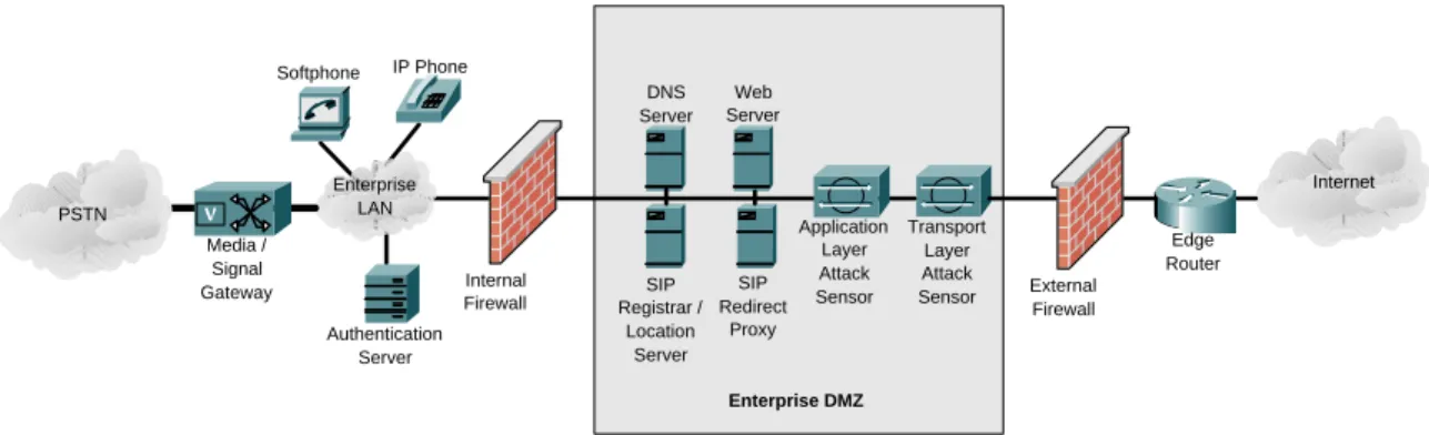
Typical enterprise networks consist of two sections: 1) the internal network and 2) the DMZ (de-militarized zone). The DMZ is connected to the public Internet through an external firewall and contains various servers that need to be accessed from external locations. This in-cludes web, mail, and domain name service (DNS) [8] servers. The internal network is connected to the DMZ by another firewall. In some architectures, the two fire-walls are replaced by a single firewall with three network interfaces [6].
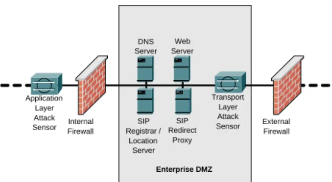
Enabling IP telephony services in enterprise networks requires additional devices to be added to the enterprise network as well as modifying the functionality of exist-ing components. Additional components that are required includes, the SIP Proxy [23], Registrar/Location Server (RLS) [23], the Media/Signal Gateway (MSG) [26] to connect to the PSTN, and various sensors as described later in Section 5. IP telephony also requires modifica-tion to the firewall. An IP telephony enabled enterprise network is shown in Figure 1.
The SIP Proxy (or H.323 Gatekeeper [12]) is placed in the enterprise DMZ. All IP telephony signaling and con-trol messages are routed through this proxy. Note that the actual media stream bypasses the proxy and sent di-rectly to the end terminal. The proxy server can support many additional features such as Spam address lists. This could include both individual clients’ lists as well as an aggregate enterprise wide list. Any incoming call request from an address in the list will result in a busy signal being sent to the calling party. The Registrar/Location Server is also located in the enterprise DMZ. Two key functions of the RLS are 1) to maintain the location (IP address) of all the end users within the enterprise and 2) to communicate with other RLSs to implement the functionalities defined in Telephony Routing over IP (TRIP) [22]. All incoming calls must have the SIP uniform resource identifier (URI) resolved to an IP address before the call can be routed to its final destination.
The Media/Signal Gateway is an application level proxy to connect the IP network to the PSTN. The MSG is com-posed of voice ports bound to voice trunks on the PSTN side and LAN connectivity in the enterprise side. Addi-tionally, it may contain a Signaling System 7 (SS7) [24] link to a Signal Transfer Point (STP). The MSG provides control and data message conversion between the two net-works. An user initiating an calls from within the enter-prise network to a PSTN end terminal, provides the MSG with authentication credentials (which the MSG verifies) before a call can be assigned to a voice trunk and initiated. In addition to the introduction of new devices in the en-terprise network, certain existing network elements must be modified [20]. The original static firewall must be re-placed with a new dynamic firewall that is capable of in-telligently parsing all layers of the network stack. The new firewall must be capable of verifying the content of each packet to ensure that only legitimate traffic is allowed through. A verification engine or Protocol Parser is loaded into the firewall for each complex protocol run over the network. For IP telephony, the Protocol Parser is respon-sible for extracting the media flow port information de-termined during the call setup phase. This information is used to open appropriate pinholes in the firewall to allow traffic that matches the call tuple. Upon the completion of a call, the Protocol Parser closes the appropriate pinholes. To enable PSTN-to-Net and Net-to-PSTN calls, the Do-main Name System (DNS) [8] service must be extended to support ENUM. In this new standard, each telephony terminal connected to the IP network is assigned an E.164 number (i.e., a telephone number) similar to a PSTN con-nected end terminal. The DNS servers must then imple-ment the ENUM protocol. In particular, ENUM uses the NAPTR DNS Resource Record type to store a mapping of E.164 number to a globally unique DNS name. All
Internet Enterprise DMZ Transport Layer Attack Sensor SIP Redirect Proxy SIP Registrar / Location Server Web Server DNS Server Edge Router External Firewall Application Layer Attack Sensor Internal Firewall Softphone IP Phone Enterprise LAN Authentication Server PSTN Media / Signal Gateway
Figure 1. IP Telephony enabled enterprise network.
ENUM names belong to the e164.arpa domain. While ENUM is required for PSTN-to-Net calls, it can also be used for Net-to-Net calls. Section 3 discusses several typ-ical call setup sequences.
Finally, this work presents new attacks sensors to be de-ployed in strategic points within the network to monitor traffic and detect the onset of DoS attacks. Figure 1 shows one possible placement of two such sensors. A Transport Layer Attack Sensor (TLAS) is positioned in the front of the DMZ to detect transport protocol layer flood attacks. An Application Layer Attack Sensor (ALAS) is used to detect IP telephony call request flood attacks targeted at either an individual user (or URIs) or to a large number of URIs within the enterprise. The detection algorithms im-plemented in these sensors and the appropriate response to these attacks are discussed in Section 5. An evaluation of the sensor placement in Figure 1 is presented in Section 6. Additional deployment issues are addressed in Section 7.
3. Normal IP Telephony Call Setup Sequences
This section outlines the normal call setup sequence in IP telephony. Detecting a DoS attack is based on detect-ing message sequences that is significantly different from these normal call setup sequences.3.1. Successful PSTN-to-Net Call
To allow calls to be placed between an end terminal in the PSTN and an end terminal in the IP network, each terminal in the IP network must be assigned an address that is capable of being specified by terminals attached to the PSTN, e.g., a phone number (or E.164 number). The result of this global naming scheme means that a PSTN terminal may not know that they are communicating with terminal on a different network. The interoperability be-tween the two network protocol stacks is performed by the MSG. PSTN End Terminal Originating Local Exchange Media / Signal Gateway SIP End Terminal SETUP (1) IAM (2) INVITE (3) Trying (4) Ringing (5) ACM (6) OK (8) ANM (9) ALERTING (7) CONNECT (10) REL (13) BYE (17) OK (18) RLC (15) DISCONNECT (12) RELEASE (14) RELEASE COMPLETE (16) Call Established (11) (RTP Data) Call Established (11) (Voice)
Figure 2. Message flow for a successful PSTN-to-Net call.
Figure 2 shows the message sequence to setup a call re-quest initiated by a end terminal connected to the PSTN to an end terminal attached to an enterprise network. The SS7 network routes1 the Initial Address Message (IAM) to the enterprise MSG. A voice port on the gateway is allocated for the incoming call. The MSG translates the E.164 number to an IP address using the ENUM exten-sions to DNS. Once the destination address has been re-solved, the gateway establishes an IP telephony (e.g., SIP) connection with the end terminal. In this scenario, the called terminal accepts the call and the message is relayed through the gateway back to the calling terminal. When either terminal terminates the call, the appropriate tear down messages are exchanged, the circuits are released, and the voice port in the gateway is freed.
1Details of SS7 routing can be found in [24] and is beyond the scope
PSTN End Termial Terminating Local Exchange Media / Signal Gateway SIP End Terminal INVITE (1) IAM (3) REL BUSY (4) Trying (2) RLC (5) ACK (7) Busy Here (6)
Figure 3. Message flow for a Net-to-PSTN call with called party unavailable.
3.2. Net-to-PSTN Call with Called Party
Unavail-able
The message sequence for a Net-to-PSTN call when the called party is available is very similar to the previ-ous case. Figure 3 shows the message sequence when the called party is unavailable. The URI in the INVITE mes-sage of a Net-to-PSTN call is formatted differently than in a Net-to-Net call. In particular, the user portion is the E.164 number of PSTN end terminal and the host address is the IP address of the MSG. Upon receiving the INVITE message (and the user validation), the MSG follows the SS7 call setup sequence. This includes allocating a voice port in the gateway and initiating an IAM message which is routed over the SS7 network to the Terminating Local Exchange (TLE). The TLE responds with a Release (REL) message with the busy flag set. This results in the circuit between the MSG and the TLE to be released. The MSG translates the REL message into a SIP Busy Here response and forwards it to the calling terminal.
3.3. Successful Incoming Net-to-Net Call
The number of call scenarios involving Net-to-Net calls is extremely large. While detailed descriptions can be found in [15], here we describe how several of the ba-sic call setups are handled. One typical situation is a call setup between an external end terminal connected to the Internet and an end terminal in the enterprise network. Note that for this example it is assumed the external termi-nal can communicate with the called termitermi-nal, i.e., it is not blocked by a static firewall. It is further assumed that the firewall deployed by the enterprise functions as described in Section 2.
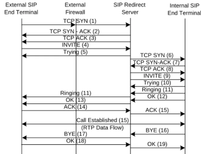
From the message sequence shown in Figure 4, it is clear that the firewall does not have an active role after the initial TCP SYN [27] packet is received. Once the incom-ing INVITE arrives at the proxy, the location of the desti-nation URI must be determined (this step is not shown). A second TCP connection is created between the proxy and end terminal and the INVITE is forwarded. All control messages are relayed through the two TCP connections bridged by the proxy. The Protocol Parser within the
fire-External SIP End Terminal External Firewall SIP Redirect Server Internal SIP End Terminal TCP SYN (1) INVITE (9) Trying (10) Ringing (11) OK (12) Call Established (15)
(RTP Data Flow) BYE (16)
OK (19) TCP SYN - ACK (2) TCP ACK (3) INVITE (4) TCP SYN (6) TCP ACK (8) TCP SYN-ACK (7) Trying (5) Ringing (11) OK (13) BYE (17) OK (18) ACK (14) ACK (15)
Figure 4. Message flow for a successful incom-ing Net-to-Net call.
wall extracts the required information from the setup mes-sages to open pinholes to allow the media stream to flow through uninterrupted. Once the call setup is complete, the media flows (RTP streams) are exchanged directly be-tween the two end terminals (assuming both have publicly routable addresses). When the Protocol Parser detects the call completion message, it instructs the firewall to closes the appropriate pinholes.
3.4. Net-to-Net Call with Called Party Unavailable
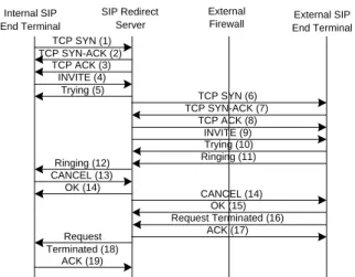
The final call setup scenario involves an enterprise ter-minal attempting to call a terter-minal connected to the Inter-net but the the call request is canceled because the called party does not answer. Just as all incoming calls must be routed through the proxy, so to must all outgoing calls. Rules are created at the firewall to block all SIP control traffic from sources other than the proxy. This, in addition to authenticating the outgoing call request at the proxy, ensures that unauthorized users cannot initiate Net-to-Net calls.The message sequence shown in Figure 5 is very similar to an incoming call request. A TCP connection is created between the calling terminal and the SIP Proxy. The initial INVITE is sent to the proxy. The IP address of the desti-nation terminal is determined and a second TCP connec-tion is created to forward the message. In this case, since the called party does not answer the incoming request in a reasonable period of time, the calling party cancels the call request. The CANCEL message generated by the call-ing terminal results in the destination terminal terminatcall-ing the call request locally. When the Protocol Parser receives the Request Terminated message, it instructs the firewall to close the appropriate pinholes.
External SIP End Terminal External Firewall SIP Redirect Server Internal SIP End Terminal TCP SYN (1) INVITE (9) Trying (10) Ringing (11) TCP ACK (3) INVITE (4) TCP SYN (6) TCP ACK (8) TCP SYN-ACK (7) Ringing (12) TCP SYN-ACK (2) Trying (5) CANCEL (13) CANCEL (14) OK (15) Request Terminated (16) ACK (17) Request Terminated (18) ACK (19) OK (14)
Figure 5. Message flow for a Net-to-Net call with called party unavailable.
4. Enumeration and Classification of Attacks
In a complex network, such as an IP telephony enabled enterprise network, there are a large number of potential vulnerabilities and attack targets. In this section we enu-merate and classify the various DoS attacks. The classifi-cation is based on the various methods that are used to mit-igate the attacks. In particular, we consider three different types of deterrence methods: 1) enterprise domain authen-tication, 2) authenticated control protocols and 3) devices (attack sensors) to detect and control the flood-based at-tacks using application and transport layer signaling mes-sages. Other classes of attacks including eavesdropping, covert channels and fraud can cause serious problems, but are beyond the scope of this work.4.1. Enterprise Domain Authentication
With the deployment of wireless networks within enter-prises, the vulnerability that an unauthorized user will be able to connect to the internal LAN has increased. Once connected to the network, an attacker can make telephony calls and launch DoS attacks. To ensure that this is not possible, all outgoing calls must be made by authenticated users. This can be implemented by a central authentica-tion server such as active directory, Kerberos [16], or Ra-dius [21]. To prevent unauthorized outgoing calls, devices within the control path must be able to query the authenti-cation server to ensure the identity of the caller.
4.2. Authenticated Control Protocols
There are several types of vulnerabilities and corre-sponding attacks that can be eliminated if the associated network elements use strong authentication. All of the
vulnerabilities that can be dealt with using strong authen-tication target the IP telephony signaling and control mes-sages. Several types of DoS attacks are possible if strong authentication is not used between the two end terminals. These include the use of SIP CANCEL request messages to drop all incoming calls to a particular terminal or to cancel all outgoing calls initiated by a terminal. Another attack is to send a BYE request message to all the termi-nals involved in an already established call. This results in the call being dropped and the terminals have to reestab-lish the call. A third type of DoS attack is caused by an attacker generating illegitimate SIP response messages in-forming the calling terminal that the called address is no longer available.
Another class of attack is based on call redirection. By injecting malicious SIP response messages into an exist-ing call control stream, an attacker can alter the servers through which the control messages are routed. In partic-ular, the messages can be routed through a compromised proxy. Other responses can be generated to cause the call-ing terminal to believe the called party has either changed locations or address. Yet another attack in this class is when an attacker re-registers with the RLS by sending a SIP REGISTER request message with a new URI for the target party. The result is that all future incoming calls to be routed to the new URI allowing the attacker to imper-sonate the target.
Through the use of strong authentication, all of the above attacks can be stopped. If each end terminal and server has un-compromised digital signatures then all messages can be authenticated. The SIP protocol includes header fields to provide authentication information as well as request authentication if it is absent. By requiring all messages to be digitally signed, an attacker will be unable to insert false requests or responses into the signaling and control message stream and impersonate various elements on the network.
4.3. Sensors to Detect and Control Flood Attacks
There are many types of attacks cannot be dealt with by provisions included in the IP telephony protocols. These include flood based attacks. To prevent and contain these types of attacks, various components in the network in-frastructure must be leveraged. The first type of flood at-tacks that network devices (also referred to as sensors) can be used to detect and control are malicious media flows. By using sampling schemes [9, 7, 14] the sensor can track the number of packets sent per flow and also monitor the size of the packets. If a flow is determined to be malicious, the sensor can either notify an administrator or activate a response mechanism like rate limiting. The ideal location where the sensor can be placed is the firewall or ingress router since these network elements can observe all thetraffic and enforce the response if a stream is determined to be malicious.
The second type of flood attacks are those that are gen-erated by application and transport layer signaling mes-sages. Dealing with this category of flood based DoS at-tacks is much more complicated since they can target mul-tiple protocol levels. There are three levels in an IP tele-phony deployment that can be targeted. To further com-plicate the situation, the attacks can come from either the Internet or from the PSTN.
The end user is the first target. The packet switching na-ture of data networks allows multiple connections to share the same physical channel. Therefore, unlike in circuit switched networks, an IP telephone terminal can receive and potentially participate in multiple calls at once. An attacker can easily overwhelm a single terminal by send-ing several call INVITE requests in a short period of time. The next target is the internal relay points in the enter-prise. For Net-to-PSTN and Net-to-Net calls this is the SIP Proxy and for PSTN originated calls it is the MSG. Each of these devices has a finite amount of resources. The MSG contains a fixed number of voice ports and a request occupies a single port for the entire duration of the call. For calls relayed through the SIP proxy, the re-source limit determined by the concurrency of the proxy server which determines the maximum number of simul-taneous calls it can handle. This limit is a function of the memory and the processing capacity of the server. A large volume of calls could result in these resources being com-pletely consumed and denying any further calls. It should be noted that this condition could occur under normal op-eration.
The final target of a flood based DoS attack are the net-work links that connect the enterprise netnet-work to the other networks. For access to the PSTN network, this is the sig-naling link between the MSG and SS7 network. The other key network link is the one that connects the enterprise to the Internet. A flood based DoS attack can saturate these links and disrupt not only IP telephony service but also other services that use these links.
5. Sensors for Detecting DoS Attacks
There is a big difference between traditional TCP traffic and enterprise IP telephony traffic. Studies of TCP traffic suggests that the average session length is between 12 and 19 seconds [29]. Enterprise telephony traffic, however, lasts much longer with at least 10% of calls have duration over 10 minutes [28]. This difference in session length imposes constraints on the sampling schemes that mon-itor connection setups and tear downs. However, it still possible to apply a single sampling process to both traf-fic models. Both IP telephony and TCP connections uti-lize a handshake for connection setup and tear-down.
Un-der normal operation, the number of initiated handshakes should be very close to the number of complete hand-shakes within a fixed observation period. A key character-istic of both application and transport layer DoS attack is that the handshaking process is not completed. Therefore, if the difference between initiated and completed hand-shakes suddenly becomes very large it is a strong indica-tion that the system is under attack. An addiindica-tional benefit of using the handshakes to detect attacks is the temporal proximity of the messages. All setup messages are trans-mitted within a relatively short time period. This allows for shorter sampling periods and hence lower detection time.
5.1. Detection Algorithm
The algorithm used in detecting the presence of an at-tack is based on the work presented in [30]. The correla-tion between the number of conneccorrela-tion establishment at-tempts and the completed handshakes is similar to the re-lationship between connection setup and tear-down. The difference can be modeled as a stationary, random process. The sensor is an implementation of Sequential Change Point Detection [1] scheme. In particular, the detection of an attack is accomplished by normalizing the difference with the average number of connections and applying the non-parametric cumulative sum method [2].
At the end of each observation periodt0,∆n is
calcu-lated to be the number of establishment attempts (EA(n)) minus the number of completed handshakes (HS(n)). To remove the dependency between the mean of∆nand the sample size, a normalized valueXn is calculate based on ∆n/C¯whereC¯is the average number of connections dur-ing the observation periodt0.C¯is defined as:
¯
C(n) =αC¯(n−1) + (1−α)HS(n) (1)
The detection of an attack within a single observation period is based upon the expected value of Xn. Under
normal operation, E(Xn) = d 1. To make detection easy, a valueois chosen such thato > dandX¯n=Xn−
o. By shiftingXn, wheneverX¯n is positive it indicates
the presence of an attack.
To ensure that short high volume attacks as well as longer low volume attacks are detected by the sensors, the algorithm includes a cumulative sum component. We de-fineynas
yn=
yn−1+ ¯Xn, if (yn−1+ ¯Xn)>0
0, otherwise (2)
The detection of an attack is determined by the value of
yn. If this value exceeds a pre-defined threshold value,T,
5.2. Recovery Algorithm
Perhaps just as important as minimizing the time to de-tect an attack, is quickly determining when an attack has ceased and returning the network to its normal state. The impact of an attack can be amplified if it takes a long time to resume normal operation. In this study, we have inves-tigated the following three different recovery algorithms.
Linear Recovery: The linear recovery approach is the
default behavior of the detection algorithm once the attack has stopped. The value ofX¯n is close to−oand thusyn
decays linearly to0. Using this algorithm does not require additional complexity to be built into the sensor, however, if the value ofynis large when the attack ceases and the
offset, o, is small, it will require a long time foryn to
drop below the thresholdT. This results in the response mechanisms to remain activated for yn
o minutes after the
attack is over.
Exponential Recovery: In this recovery algorithm,yn
is decremented using a multiplicative factor onceX¯n<0.
The value ofynis calculated by:
yn=
yn−1+ ¯Xn, if ¯Xn>0
yn−1−o
i, otherwise
IfX¯n ≤ 0, the value of i is incremented afteryn is
calculated. Onceynreturns to0or begins to increase, the
value ofiis reset to1. Using this approach, the time for which the attack response mechanism remains active after the attack has ceased islogo(yn)minutes.
Reset after Timeout: This scheme is an extension of
the linear recovery algorithm. When the value ofyn
be-gins to drop, a timer, E, is started. The value ofyn is
allowed to decay linearly until the timer expires. At the expiration of the timer, if the value of yn is still above
the thresholdT, it is reset to0. Unlike the other two ap-proaches, by using discrete timeouts it is possible to place a fixed upper bound,E, on the time the response mecha-nisms will be in place after the attack has stopped.
5.3. Application Layer Attack Sensor (ALAS)
To detect flood attacks targeted at a particular end ter-minal, the detection algorithm presented in the previous section is applied to the application level traffic. In Sec-tion 3, it was shown that each legitimate call using the SIP protocol relies on an INVITE and OK message pair to complete the setup phase. Tracking the volume of this message pair and applying the detection algorithm, it is possible to determine when a particular terminal is receiv-ing a volume of calls it cannot handle.
To ensure that each end terminal is protected against flood attacks, the ALAS must monitor each URI indepen-dently. This is accomplished by a tracking table within the sensor. During an observation period, the URI is ex-tracted from INVITE and OK messages and is stored in the table. Each URI entry has an associated counter to track the number of INVITEs and OKs observed. At the expiration of the sampling period, the decision algorithm is executed for all URIs in the tracking table. The increase in overhead required to monitor individual URIs is accept-able because it allows the response mechanism to provide protection only for those affected by the attack. Using an aggregate based approach would result in all end ter-minals being affected by the response mechanisms if an attack was detected.
Upon detecting an attack targeted at an individual URI, the ALAS sends a control message to the SIP Proxy to in-dicate the detection of an attack. Within the message is a severity indicator. This value is determined by the value ofyndiscussed in the previous section. In response to the
control message, the proxy initiates the attack response by returning Temporarily Unavailable or Busy Here mes-sages to a fraction of incoming calls to the corresponding URI. The severity indicator in the control message deter-mines the probability that a new incoming call will be al-lowed to pass through the proxy. In the worst case sce-nario, all calls to the URI will be blocked by the proxy. The call restrictions are only removed when the ALAS in-structs the proxy to do so.
5.4. Transport Layer Attack Sensor (TLAS)
As stated previously, using the both setup and tear-down control messages for IP telephony traffic is not a reason-able solution for detecting DoS attacks. To identify at-tacks targeted at the network stack, a sensor can be built to monitor TCP SYN and ACK packets. The arrival time between these packets is typically very small. This allows the sensor to use a short observation period and thus en-sure quick detection of an attack.The location of the TLAS within the network allows for it to be leveraged to protect all machines in the DMZ if needed. The need to monitor the related SYN and ACK packets at an individual connection level or end terminal is not appropriate because of the extremely large volume of connections and the lack of trustworthiness of source addresses. Therefore, an aggregate approach is adopted in determining the presence of an attack. DoS attacks target-ing the network layer of a device require a large volume of traffic. Therefore, monitoring at an aggregate level will show an anomaly when a network is under attack.
The pair of SYN and ACK packets can be used to detect an attack because of two reasons. First, the external fire-wall is a stateful device and will not allow ACK packets
not associated with an existing connection to pass. The result of this is that an attacker cannot flood a target with a mixture of both SYN and ACK packets in an attempt to hide the attack from the TLAS since the ACKs will not traverse the firewall.
The second reason the SYN and ACK packets are a good choice is that they both come from an external ter-minal and are connected using information generated by an internal terminal. It is very difficult for an attacker to spoof the source address of a SYN packet and then gener-ate a correct ACK packet because the SYN-ACK packet generated by the target enterprise server will be sent to the spoofed address. The attacker might be able to view the SYN-ACK packet if they were located on the data path be-tween the target and the spoofed address, but this situation is rare.
Using the SYN and ACK pair also allows for a short observation period. The time between the two packets is equal to the round trip time between the enterprise server and the initiating machine. In the worst case, this value would be on the order of several seconds. This close time proximity between packets allows for a very fast detection of attacks.
The response mechanisms for a transport layer attack can be classified into three categories: end server re-sponse, firewall rere-sponse, and router response. At the end server SYN cache [17] or SYN cookies [3] can be used to reduce the amount of resources consumed by an incom-ing SYN packet. Rate limitincom-ing at the firewall can be acti-vated to decrease the frequency of incoming SYN packets to the servers. Finally, Pushback and Aggregate Conges-tion Control [18, 10] can be used by upstream providers to drop offending flows before they reach an enterprise net-work’s border.
6. Experimental Evaluation of Initial Attack
Sensor Deployment
6.1. DoS Attack Models
To evaluate the performance of the ALAS, the following three different DoS scenarios were considered.
Limited DoS Attack: It involves a single URI being
tar-geted by one or more attackers. The volume of incoming attack calls was varied between different runs of the attack from a low annoyance level of one hostile call per minute to an overwhelming level of 10 or more hostile calls per minute. This attack is extremely focused on disrupting on a small number of end users and not on degrading the level of service throughout the enterprise.
Stealth DoS Attack: This attack involves one or more
attackers targeting a large number of URIs within the
en-terprise. Each URI only receives a very low volume of calls (e.g., one per minute or less). This results in a large consumption of network wide resources while not modi-fying the statistical network traffic level by a significant amount.
Aggressive DoS Attack: This attack can be viewed as a
combination of the two previous cases. The impact and detection of this attack can widely vary. In evaluating the ability of ALAS to detect this attack, a subtle vari-ant was chosen because it is more difficult to detect than extremely large versions. One or more attackers initiated a low level of calls to a moderate number of URIs. The impact of the attack was two fold, 1) the end users were successfully disrupted from their normal operations and 2) a large amount of network resources were consumed causing other services to suffer.
For each scenario, the ALAS did detect the attack at either the individual URI level or at the aggregate level. In the aggressive attack, both TLAS and ALAS detected the attack. The next section discusses several variations of the initial attack detection algorithm.
6.2. Enterprise User Model
The user model was constructed to closely match that of a large enterprise. The distribution of calls to differ-ent URIs is shown in Table 1. The majority of URIs re-ceived a very low volume of calls during the simulation period. However, there are certain addresses within an enterprise (e.g., help desk, front office, etc.) that receive a much higher volume of calls. To determine if the vol-ume of legitimate calls affected the performance of the sensors, both high and low volume users were included in the model.
Table 1. Enterprise Call Distribution
Calls Received During Simulation Number of URIs
1 500
2 - 5 400
6 - 10 80
11 - 20 20
6.3. Simulation Parameters
ALAS was evaluated using three different recovery techniques. The recovery techniques impacted how the sensor operated once an attack had stopped. For each re-covery algorithm, four simulations were run. Each sim-ulation lasted for thirty minutes with the detection algo-rithm sampling the volume of traffic and calculating statis-tics each minute.
0 5 10 15 20 25 30 35 40 45 1 3 5 7 9 11 13 15 17 19 21 23 25 27 29 Time (minutes) C a lc ul a te d V a lu e o f Y n
Attack 1 - Low Volume URI Attack 2 - High Volume URI
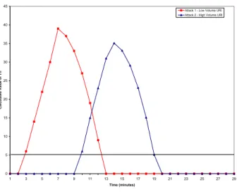
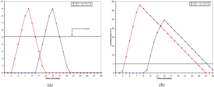
Figure 7. Limited DoS using Exponential Re-covery (ouri= 2andTuri= 5) (a) Attack 1 with
4 attack calls per minute and (b) Attack 2 with 10 attack calls per minute.
The first two were limited DoS attacks using 4 hostile calls per minute and 10 hostile calls per minute to a single URI. To ensure that ALAS would detect the attack regard-less of the volume of legitimate calls the URI received, two URIs were targeted during each simulation. One of the URIs received 2 to 5 calls during the simulation period and the other received over 20 calls. The attacks were each 5 minutes in length and started on the second and seventh minute of the simulation.
The other two simulations used a stealth DoS attack and an aggressive DoS attack, respectively. The stealth attack targeted 200 unique URIs out of the 1000 URIs within the enterprise and generated one call a minute to each URI. The aggressive attack used 50 unique URIs, but increased the number of calls to 3 per minute to each target. The attacks lasted 10 minutes and began on the second minute of the simulation.
The offset values,ouriandoagg, were set to 2 and 1,
re-spectively. The attack thresholds,TuriandTagg, were set
to 5 and 2. The valueEfor the discrete timeout algorithm was set to 2.
6.4. Experimental Results
For each sensor configuration, two key metrics were used to determine its performance: attack detection time and system recovery time. Figures 6, 7 and 8 show the sensor’s detection of a limited DoS attack. Figures 9 and 10 show the detection plots for an aggressive and stealth DoS attack respectively.
By choosing the offset and threshold values appropri-ately, the false alarm rate was reduced to zero for all
sim-0 5 10 15 20 25 30 35 40 1 3 5 7 9 11 13 15 17 19 21 23 25 27 29 Time (minutes) C a lc ul a te V a lu e of Yn
Attack 1 - Low Volume URI Attack 2 - High Volume URI
Figure 8. Limited DoS using Reset after Time-out (ouri = 2 andTuri = 5) (a) Attack 1 with 4
attack calls per minute and (b) Attack 2 with 10 attack calls per minute.
0 0.5 1 1.5 2 2.5 3 3.5 1 3 5 7 9 11 13 15 17 19 21 23 25 27 29 Time (minutes) C a lc u la te d v a lu e o f Y n
50 URIs with 3 calls per minute
Figure 9. Aggregate level detection of Aggres-sive DoS attack (oagg= 1andTagg= 2).
0 1 2 3 4 5 6 7 8 9 10 1 3 5 7 9 11 13 15 17 19 21 23 25 27 29 Time (minutes) C a lc u la te d V a lu e o f Y n
Attack 1 - Low Volume URI Attack 2 - High Volume URI
Threshold 0 5 10 15 20 25 30 35 40 1 3 5 7 9 11 13 15 17 19 21 23 25 27 29 Time (minutes) C a lc ul a te d V a lu e o f Yn
Attack 1 - Low Volume URI Attack 2 - High Volume URI
(a) (b)
Figure 6. Limited DoS Experiment using Linear Recovery (ouri = 2and Turi = 5) (a) Attack 1 with 4
attack calls per minute (b) Attack 2 with 10 attack calls per minute.
0 1 2 3 4 5 6 7 8 1 3 5 7 9 11 13 15 17 19 21 23 25 27 29 Time (minutes) C a lc u la te d V a lu e o f Y n
200 URIs with 1 call per minute
Figure 10. Aggregate level detection of Stealth DoS attack (oagg= 1andTagg= 2).
ulations. Lowering the values would allow for stealthier attacks to be detected, but would have also increased the false alarm rate.
The attack detection times for the four DoS attacks types are shown in Table 2. The results in Figures 6, 9 and 10 show that the larger the volume of attack calls, the shorter the detection time. The one result that might seem surprising is the stealth attack was detected in less time than the aggressive attack. This is because the overall call volume was greater for the particular stealth and ag-gressive attacks used in this study. The agag-gressive attack generated 150 attack calls per minute (three to 50 differ-ent URIs) while the stealth generated 200 attack calls per minute (one to 200 different URIs).
Table 2. Detection time for various DoS attacks
Attack Type Detection Time
4 calls/min Limited DoS 4 minutes (URI level) 10 calls/min Limited DoS 2 minutes (URI level) 50 URI Aggressive DoS 6 minutes (URI level)
8 minutes (aggregate level) 200 URI Stealth DoS 4 minutes (aggregate level) To evaluate the performance and impact of the differ-ent recovery algorithms, a limited DoS attack targeting a low volume URI was used. Table 3 shows the amount of time required from the end of the attack until the levels in the sensor dropped below the threshold. Figures 6b, 7, 8 provide a graphical representation of the recovery rithms operation. As expected, the linear recovery algo-rithm performance was substantially lower than the other two. For real world deployments, the increase in sensor
complexity to use the exponential or reset after timeout al-gorithms is acceptable because of the significant increase in performance. The cost of a poor recovery algorithm is substantial if the response mechanisms remain activated much beyond the end of the attack.
Table 3. Recovery time for Limited DoS attack on a small number of URIs
Attack Volume - Recovery Alg. Recovery Time 4 calls/min - Linear Recovery 3 minutes 10 calls/min - Linear Recovery 17 minutes 10 calls/min - Exponential Recovery 6 minutes
10 calls/min - Reset after Timeout 3 minutes To ensure that the detection algorithm works indepen-dent of the volume of legitimate traffic a received by any URI, we considered limited attacks targeting two URIs from different user categories in Table 1. For users with a high volume of legitimate traffic, the valueC¯(n)in Equa-tion 1 is large. This impacts the normalizaEqua-tion of the dif-ference between connection attempts and establishments. The larger the value ofC¯(n), the greater in reduction of
Xn because Xn = ∆n/C¯(n). Figure 6b shows the
im-pact of this normalization. The peak value of the attack on the high volume URI is 25% less than the low volume URI target.
7. Other Deployment Issues
The sensor placement in Figure 1 is only one of several possibilities. This section examines to impact of deploy-ing ALAS at other locations in the network.
7.1. ALAS behind the SIP Proxy
Instead of placing the ALAS in front the SIP Proxy, it is possible to place it in behind the SIP Proxy as shown in Figure 11. However, by doing so several characteristics of the traffic seen by the sensor changes. During an attack, the sensor will not continue to see all incoming calls. The various response mechanisms activated in the proxy will influence the traffic pattern seen by the sensor. It will not receive notification nor be able to detect which calls are blocked at the proxy without significantly modifying the interaction between the proxy and sensors. The detection and the recovery algorithms need to be modified for this architecture. This is the scope of future work.
7.2. Protection for PSTN Originated Attacks
In a converged network, the Internet is not the only source of attacks. While more difficult, it is possible to launch an attack from the PSTN. It becomes more diffi-cult because a large number of individual phones must beEnterprise DMZ Transport Layer Attack Sensor SIP Redirect Proxy SIP Registrar / Location Server Web Server DNS Server Internal Firewall Application Layer Attack
Sensor ExternalFirewall
Figure 11. ALAS placed behind the SIP Proxy.
PSTN Media / Signal Gateway Application Layer Attack Sensor Softphone IP Phone Enterprise LAN Authentication Server
Figure 12. Detecting PSTN Based DoS Attacks
marshaled and the attack must be coordinated between a large number of individuals. In any case to detect and con-trol such attacks, another possible deployment location for an ALAS is in series with the MSG (Figure 12). A sen-sor placed here would operate almost identically to one placed behind the SIP Proxy. The traffic patterns would be consistent because the enforcement mechanism is placed before the sensor on the network path. The difference be-tween the two deployment locations is the response mech-anisms that are utilized. For PSTN based attacks, the MSG must generate Transfer Controlled (TFC) messages or Release Busy messages for the targeted E.164 numbers depending on the severity of the attack [24].
8. Related Work
Detection and protection of DoS attacks has been a pop-ular topic in recent years. The trend has been to focus on either protection and/or reduction of the impact of an at-tack or detection of an atat-tack.
Yau et al [31] developed a scheme to include throttles in the network routers that use a leaky-bucket approach to reduce the incoming rate of traffic to targeted servers. Another approach to countering DoS attacks at the net-work infrastructure is the use of Pushback and Aggregate Congestion Control [18, 10, 13].
based networks. In [4], Burns and Ghosal examine media stimulated focused overloads in the PSTN. As in an IP DoS attack, the target of a focused overload is unable to operate normally.
Other work has been done on reducing the impact of an attack on the targeted terminals. Both SYN cookies [3] and SYN cache [17] are extensions to the network proto-col stack in an attempt to reduce the resource consumption of each incoming SYN packet.
A third approach to reducing the impact of an attack is from a quality of service (QoS) point of view. By limiting the amount of resources each type of traffic can consume, the extent of a DoS attack can be severely limited. In [11], Garg and Reddy present a prototype system capable of enforcing QoS restrictions on various resources including network bandwidth, protocol state memory buffers and CPU cycles.
The other category of research has been on quickly and effectively detecting the presence of an attack. Wang et al [30] introduced a simplistic, yet powerful, algorithm that exploits the normal behavior of TCP traffic to detect the presence of a SYN flood attack. Their algorithm was used as a basis for the algorithms presented in this paper.
9. Conclusion
This study provided a detailed examination of DoS at-tacks against IP telephony enabled enterprise networks. It was shown that a large class of attacks can only be handled by implementing dedicated sensors in an enterprise net-work. The operation and implementation of sensors at the transport and application layers were described in detail. Each of these sensors exploited a non-parametric cumu-lative sum algorithm to detect the presence of an attack. In addition to attack detection, we examined the impact and performance of three different recovery algorithms. A quantitative analysis using a simulated enterprise environ-ment showed that the detection algorithm correctly identi-fied three different types of DoS attacks and we quantiidenti-fied the difference between the different recovery algorithms. Further work needs to be carried out to understand the im-pact of the various sensor parameters and the placement of the sensors. Work is also required to integrate the tech-niques developed in this paper with sensors to detect DoS attacks using malicious media flows.
Acknowledgment
We would like to thank the anonymous reviewers and Radha Poovendran for their comments that helped us in preparing the final version of the paper.
References
[1] M. Basseville and I. V. Nikiforov. Detection of Abrupt Changes: Theory and Application. Prentice Hall, 1993. [2] B. E. Brodsky and B. S. Darkhovsky. Nonparametric
Methods in Changepoint Problems. Kluwer Academic Publishers, 1993.
[3] Bronzesoft.org. SYN cookies firewall. World Wide Web,
http://www.bronzesoft.org/projects/ scfw, 2002.
[4] J. Burns and D. Ghosal. Design and analysis of a new al-gorithm for automatic detection and control of media stim-ulated focused overloads. In Proceedings of International Teletraffic Congress, Edinburgh, June 1997.
[5] C. C. Center. Trends in denial of service attack tech-nology. World Wide Web,http://www.cert.org/ archive/pdf/DoS_trends.pdf, Oct. 2001. [6] W. Cheswick and S. Bellovin. Firewalls and Internet
Se-curity. Addison Wesley Longman, Inc., New York, NY, 1st edition, 1994.
[7] K. Claffy, G. Polyzos, and H. Braun. Application of sam-pling methodologies to network traffic characterization. In Proceedings of ACM SIGCOMM, San Francisco, Sept. 1993.
[8] R. Daniel and M. Mealling. RFC 2168: Resolution of Uni-form Resource Identifiers using the Domain Name Sys-tem, June 1997.
[9] C. Estan and G. Varghese. New directions in traffic mea-surement and accounting. In Proceedings of ACM SIG-COMM, Pittsburg, Aug. 2002.
[10] S. Floyd and V. Jacobson. Random Early Detection Gate-ways for Congestion Avoidance. IEEE/ACM Transactions on Networking, 1(4):397–413, Aug. 1993.
[11] A. Garg and A. Reddy. Mitigation of dos attacks through qos regulation. In Proceedings of IEEE International Workshop on Quality of Service (IWQoS), Miami Beach, May 2002.
[12] I.-T. R. H.323. Visual telephone systems and equipment for local area networks which provide a non-guaranteed quality of service, May 1996.
[13] J. Ioannidis and S. Bellovin. Implementing pushback: Router-based defense against DDoS attacks. In Proceed-ings of Network and Distributed System Security Sympo-sium, San Diego, Feb. 2002.
[14] J. Jedwab, P. Phall, and B. Pinna. Traffic estimation for the largest sources on a network, using packet sampling with limited storage. Technical Report 35, Hewlett Packard Labs, Mar. 1992.
[15] A. Johnston, S. Donovan, R. Sparks, C. Cunningham, D. Willis, J. Rosenberg, K. Summers, and H. Schulzrinne. Internet draft: SIP call flow examples, Apr. 2002. Work in Progress.
[16] J. Kohl and C. Neuman. RFC 1510: The Kerberos Net-work Authentication Service (V5), Sept. 1993.
[17] J. Lemon. Resisting SYN flood DoS attacks with a SYN cache. In Proceedings of USENIX BSDCon 2002, San Francisco, Feb. 2002.
[18] R. Mahajan, S. Bellovin, S. Floyd, J. Vern, and P. Scott. Controlling high bandwidth aggregates in the network.
Technical Report 1, University of California, Berkeley -International Computer Science Institute, Feb. 2001. [19] J. Mirkovic, J. Martin, and P. Reiher. A taxonomy of
DDoS attacks and DDoS defense mechanisms. Technical Report 18, University of California, Los Angeles - Com-puter Science Department, 2002.
[20] B. Reynolds and D. Ghosal. STEM: Secure Telphony Enabled Middlebox. IEEE Communications Magazine, 40(10), Oct. 2002.
[21] C. Rigney, S. Willens, A. Rubens, and W. Simpson. RFC 2865: Remote Authentication Dial in User Service (RA-DIUS), June 2000.
[22] J. Rosenberg and H. Schulzrinne. RFC 2871: A Frame-work for Telephony Routing over IP, June 2000. Status: Informational.
[23] J. Rosenberg, H. Schulzrinne, G. Camarillo, A. Johnston, J. Peterson, R. Sparks, M. Handley, and E. Schooler. In-ternet draft: SIP: Session initiation protocol, Feb. 2002. Work in Progress.
[24] T. Russell. Signaling System 7. McGraw-Hill, New York, NY, 3rd edition, 2000.
[25] C. Schuba, I. Krsul, M. Kuhn, E. Spafford, A. Sundaram, and D. Zamboni. Analysis of a denial of service attack on TCP. In Proceedings of the 1997 IEEE Symposium on Security and Privacy, pages 208–223. IEEE Computer Society, IEEE Computer Society Press, May 1997. [26] H. Schulzrinne and J. Rosenberg. Internet Telephony:
Ar-chitecture and Protocols - an IETF Perspective. Computer Networks, 31(3):237–255, 1999.
[27] R. Stevens. TCP/IP Illustrated Volume 1: The Protocols, volume 1. Addison Wesley Longman, Inc., Reading, MS, 1st edition, 1994.
[28] Telecost. Enterprise call durations distributions. World Wide Web,http://www.telecost.co.uk/ pages/OnCallDurations.htm, 2002.
[29] K. Thompson, G. J. Miller, and R. Wilder. Wide-area in-ternet traffic patterns and characteristics. IEEE Network, 11(6), Dec. 1997.
[30] H. Wang, D. Zhang, and K. Shin. Detecting SYN flooding attacks. In Proceedings of IEEE INFOCOM 2002, New York, June 2002.
[31] D. Yau, J. Lui, and F. Liang. Defending against distributed denial-of-service attacks with max-min fair server-centric router throttles. In Proceedings of IEEE International Workshop on Quality of Service (IWQoS), Miami Beach, May 2002.