TABLE OF CONTENTS
1. GENERAL ... 1
1.1 UBC Videoconference Rooms... 1
1.2 Responsibilities Related to the UBC Videoconference Rooms... 1
1.3 Interpretation... 2
2. PROJECT BACKGROUND ... 3
3. OVERVIEW OF THE UBC VIDEOCONFERENCE ROOMS... 3
3.1 Lecture Theatre/Videoconference Room - 120 seat ... 3
3.2 Projection Room ... 4
3.3 Medium Videoconference/Seminar Room (35 seats) ... 5
3.4 Videoconference/Seminar Room (16 seats) ... 5
3.5 Small Videoconference Room (8 seats)... 5
3.6 Central Videoconference Operator/Rack Room... 6
4. GENERAL REQUIREMENTS FOR ALL OF THE UBC VIDEOCONFERENCE ROOMS... 6
4.1 Introduction ... 6
4.2 Security... 6
4.3 Mechanical... 6
4.4 Heat Load ... 7
4.5 Acoustics ... 7
5. ROOM SPECIFIC REQUIREMENTS... 14
5.1 Lecture Theatre/Videoconference Room - 120 seat ... 14
5.2 Projection Room ... 20
5.3 Medium Videoconference/Seminar Room (35 Seats)... 22
5.4 Interior Design ... 27
5.5 Small Videoconference/Seminar Room (16 seats) ... 27
5.6 Small Videoconference Room (8 Seats) ... 30
5.7 Central Videoconference Operator/Rack room ... 32
6. REFERENCE DRAWINGS ... 35
6.1 Lecture Theatre/Videoconference Room – 120 Seat ... 35
6.2 Medium Videoconference/Seminar Room (35 seats) ... 36
6.3 Small Videoconference/Seminar Room (16 seats) ... 36
6.4 Small Videoconference Room (8 seats)... 37
APPENDIX 3B
UBC VIDEOCONFERENCE ROOM SPECIFICATIONS 1. GENERAL
1.1 UBC Videoconference Rooms
(a) This Appendix 3B sets out specifications for the design and construction of the following spaces within the UBC Clinical Academic Campus:
(1) lecture theatre/video conference room (120 seats) [Ref 36 in the schedule of accommodation included in Section 10 of Clinical Specification];
(2) projection room [Ref 35 in the schedule of accommodation included in Section 10 of Clinical Specification];
(3) medium video conference/seminar room (35 seats) [Ref 23 in the schedule of accommodation included in Section 10 of Clinical Specification];
(4) small video conference/seminar room (16 seats) [Ref 22 in the schedule of accommodation included in Section 10 of Clinical Specification];
(5) small video conference room (8 seats) [Ref 14 in the schedule of accommodation included in Section 10 of Clinical Specification]; and
(6) central video conference operator/rack room [Ref 24 in the schedule of accommodation included in Section 10 of Clinical Specification],
(collectively, the “UBC Videoconference Rooms”). This Appendix does not apply to other videoconference rooms within the Facility.
(b) Additional specifications for the UBC Videoconference Rooms are described in the Clinical Specification and in Schedule 3 [Design and Construction Specifications].
(c) The videoconference equipment, furniture and millwork required for the UBC Videoconference Rooms is described in the Equipment List and in the Equipment Data Sheets.
1.2 Responsibilities Related to the UBC Videoconference Rooms (a) UBC Responsibilities
As described in Appendix 2E [Equipment and Furniture], UBC intends to procure, deliver, install and commission all videoconference equipment required for the UBC Videoconference Rooms (which equipment is Category E1 Equipment), using funding provided by the Province of British Columbia.
(b) Authority Responsibilities
As described in Appendix 2E [Equipment and Furniture], the Authority will procure, deliver, setup, install and commission all office furniture required for the UBC Videoconference Rooms (which furniture is Category D Equipment).
(c) Project Co Responsibilities
Except as described in Sections 1.2(a) and 1.2(b) above, Project Co will procure, deliver, setup, install and commission all equipment (including any Category F Equipment) and materials and perform all design and construction required to complete the UBC Videoconference Rooms in accordance with the requirements of this Agreement (including this Appendix) so that the UBC Videoconference Rooms are ready to be occupied and used for their intended purposes as described in this Appendix, including design and construction of all building systems, infrastructure and equipment required to support the videoconference equipment. 1.3 Interpretation
(a) This Appendix is written as an output specification and defines what Project Co must achieve in the Design and Construction of the UBC Videoconference Rooms. Except as expressly stated otherwise, Project Co will carry out the Design and Construction of the UBC Videoconference Rooms as required and contemplated by each provision of this Appendix whether or not the provision is written as an obligation of Project Co or is stated in the imperative form.
(b) The following Acronyms are used in this Appendix: (1) AFF – Above the Finished Floor
(2) AV - Audiovisual
(3) CAC - Ceiling Attenuation Class (4) DMP - Distributed Medical Program (5) DSP - Digital Signal Processor (6) FoM – Faculty of Medicine
(7) FSTC - Field Sound Transmission Class (8) GWB – Gypsum Wall Board
(9) HVAC – Heating, ventilation and air conditioning (10) MDV – Most Distant Viewer
(12) NC – Noise Criterion (13) SH – Screen Height
(14) STC - Sound Transmission Class (15) IIC – Impact Insulation Class
2. PROJECT BACKGROUND
The UBC Videoconference Rooms will be used for UBC’s Distributed Medical Program (DMP).
Central to the DMP is the distributed learning model (or distance education), where lectures and labs are delivered both to students in the same physical location as the lecturer, and simultaneously to students at multiple remote locations. The lectures are viewed by all students in the remote locations in real time, and are configured to provide an equivalent educational experience for all students, regardless of their geographical location. The UBC Faculty of Medicine uses videoconference-capable audiovisual systems to deliver distance education, in facilities that are designed to meet the specialized functional requirements of medical education.
The DMP has videoconference facilities located at three types of campuses located across BC:
(a) University campuses (UBC, UVic, and UNBC), for delivery and support of Year 1 and 2 undergraduate medical education. A fourth medical school building, at UBCO in Kelowna, will open in 2011;
(b) Clinical academic campuses, for delivery and support of undergraduate and post graduate programs, located at regional hospitals throughout BC;
(c) Affiliated regional centres, for delivery and support of undergraduate and post graduate programs, located at regional hospitals throughout BC. The difference between clinical academic campuses and affiliated regional centres is in the number and size of education facilities each contains. 3. OVERVIEW OF THE UBC VIDEOCONFERENCE ROOMS
The descriptions in this section are provided to give Project Co an understanding of the features and functionality that will be implemented in these rooms.
3.1 Lecture Theatre/Videoconference Room - 120 seat
The lecture theatre/videoconference room will be equipped with a permanently installed AV and videoconference system. The AV system in the lecture theatre will have two side by side projection screens for the simultaneous display of electronic images including video, document camera, computer based digital slides, computer presentation, computer based X-ray as well as image/sources from the remote locations.
The permanently installed lectern in the lecture theatre will be the main system control point housing the DVD, VCR, the computer interface, the control touch screen and the document camera. The lectern will require an 18” LCD touch screen monitor, which will serve as preview and confidence monitor. The lectern will also have the
“write on” surface providing electronic annotation capabilities. This will provide the presenter with the ability to annotate the computer-generated image displayed on the local, as well as the remote location, screens.
Additionally, the lecture theatre requires two 46” LCD preview/confidence monitors located in front of the first row tables. They will be mounted in secure millwork housing. The purpose of these monitors is to provide the lecturers with the ability to move freely while still seeing the selected sources and students in remote locations.
The audio systems for the lecture theatre perform two key functions: playback of multimedia material from various sources, and processing and playback of the incoming audio from the distance education system. The lecture theatre will have one wired lectern microphone and two wireless instructor microphones. One wired push-to-talk microphone will be shared between each pair of seats for all participant seating areas. These microphones will be gooseneck type microphones, permanently mounted to the audience area fixed tables. The AV playback system will use loudspeakers flanking the large screen displays located on the front wall.
The centrepiece of the audio systems will be a centralized Digital Signal Processor (DSP) and matrix mixer/router system that will allow the various microphone and AV source inputs to be sent to the appropriate signal paths with suitable signal processing. Automixers will be used to mix all microphones to manage feedback and will be simultaneously mixed and processed with automatic gain control and digital echo-cancelling. This process will be used for the video conference feed.
The AV source inputs will be routed to the AV playback speakers, video conference sends and archival feeds as required. The DSP will also handle equalization, signal delays, compression, limiting, level adjustment and other required audio functions.
The control system will integrate the function of the many devices in the lecture theatre’s AV and videoconference systems. All of the required remote-controllable devices will be connected to central processors, allowing control to be from a 15” colour control touch panel housed in the lectern, or through the operator computer located in the Central Video Conference Operator/Rack Room. This will also be connected to the LAN using the control system web interface.
For the purpose of connecting to remote sites, the lecture theatre will also be equipped with videoconferencing based distance education capability, allowing simultaneous transmission of up to two video and high resolution graphics channels. This will be accomplished for the lecture theatre via one videoconferencing CODEC and one KVM VNC server collaboration application data link. These systems can be controlled from the control system touch panels, or the network interfaces from the operator computer.
3.2 Projection Room
The projection room will house two video/data projectors, as well as a camera. The projection room will also have an operator position to allow an operator to monitor and support the videoconference sessions. Finally, the projection room will house 3 equipment racks that hold videoconference and AV system equipment for the lecture theatre/videoconference room.
3.3 Medium Videoconference/Seminar Room (35 seats)
The medium videoconference/seminar room will make use of class-room style table layouts with the lectern located at the front, and will be equipped with a permanently installed AV and videoconference system. The AV system will consist of three side by side 85 ” flat screens for simultaneous display of video, document camera, computer based digital slides, computer presentation, computer based X-ray and image sources from the remote locations.
The central video conference operator/rack room will house the main AV equipment racks for this room, as well as an operator position for monitoring and support of the medium videoconference/seminar room.
The lectern will be the main system control point, housing the DVD/VCR combo unit, the computer interface, the wired control touch screen and the document camera. The 18” touch screen will serve as a preview and RGB signal confidence monitor and provide a “write on” surface for electronic annotation. This will provide the presenter with the ability to annotate the computer-generated image displayed on the local, and the remote location screens. Video sources such as DVD and videotapes will not have annotation capabilities. The medium videoconference/seminar room will also be equipped with three 46” LCD preview/confidence monitors located at the room back wall, to provide the lecturers with the ability to move freely while still seeing the selected sources and students in remote locations.
The audio systems and control system for the medium seminar room will have similar features and functionality as that described for the lecture theatre in Section 3.1. The medium seminar room will also have videoconferencing based distance education capability as described for the lecture theatre.
3.4 Videoconference/Seminar Room (16 seats)
The 16-seat videoconference/seminar room will require a permanently installed AV and videoconference system. The display system will consist of two front wall mount, 85” flat screen high resolution displays capable of
displaying video, computer and videoconferencing presentation image sources.
The audio system will have an AV playback system to support the playback of multimedia material, and to support the incoming audio from a videoconference. The AV playback system will use loudspeakers flanking the wall mount 85” flat screen displays located on the front wall.
The AV system for this room will be controlled by the IR remote of the videoconferencing CODEC and the robotic camera. A separate control system will permit an operator to control the AV system from a computer located in the central videoconference operator/rack room.
The AV equipment for this room will be mounted in secure, lockable AV millwork located in the room itself. 3.5 Small Videoconference Room (8 seats)
The 8-seat small videoconference room will require a stand-alone, movable videoconference system. The system will consist of a single 50” flat-panel display, robotic camera, stand, and an IR remote control.
3.6 Central Videoconference Operator/Rack Room
The central videoconference operator/rack room is required to support all of the videoconference sessions conducted from SMH and will be equipped to allow operators to support and monitor simultaneous sessions in more than one of the videoconference rooms. The central videoconference operator/rack room will house 4 AV equipment racks, 3 fully equipped monitoring stations consisting of multiple displays and other monitoring equipment, and will have sufficient desk space for 3 operators. This room will also house a dedicated videoconference operator position for monitoring the medium videoconference/seminar room.
4. GENERAL REQUIREMENTS FOR ALL OF THE UBC VIDEOCONFERENCE ROOMS 4.1 Introduction
(a) The purpose of this Section 4 is to describe general requirements that are applicable to all of the UBC Videoconference Rooms. Accordingly, all requirements set out in this Section 4 apply to all of the UBC Videoconference Rooms unless expressly stated otherwise. Additional requirements for specific rooms are set out in Section 5 of this Appendix.
4.2 Security
(a) Each of the UBC Videoconference Rooms will:
(1) be self contained, as described in the Clinical Specification;
(2) be lockable and provided with secure access (24 hours, seven days a week) via swipe or proximity card systems; and
(3) have monitored intrusion alarm systems.
(b) There will be no windows along the perimeter walls in any of the UBC Videoconference Rooms except for windows joining:
(1) the projection room and lecture theatre/videoconference room (see Section 5.1(a)(6)); and (2) the central videoconference operator/rack room and medium videoconference/seminar
room (see Section 5.7(a)(5)). 4.3 Mechanical
(a) Protection from Water Damage
(1) All of the UBC Videoconference Rooms will be designed and constructed to protect the videoconference equipment from damage caused by plumbing failures and excessive condensation. See reference drawings: #14.0, #4.1, #7.1, #10.0, and #11.0.
(2) Where AV equipment racks must be located directly beneath plumbing lines, equipment will be shielded from potential non-sprinkler related water damage.
4.4 Heat Load
(1) There is a significant amount and variety of equipment used in videoconference systems, such as projectors, computers, video displays, switching units, and other signal
processing equipment. This equipment generates a substantial heat load. Accordingly, Project Co will provide an HVAC system for the Building that is capable of maintaining the UBC Videoconference Rooms within acceptable operating parameters as defined in Schedule 3 [Design and Construction Specifications] and the additional operating parameters described in Section (2) below.
(2) Specialized temperature and humidity requirements for the Projection Room and Central Videoconference Operator/Rack Room, above and beyond those defined in Schedule 3, are as follows:
(A) The long term ambient room temperature target for these rooms to operate in is 22 degrees Celsius.
(B) The maximum short-term sustainable ambient temperature for these rooms is 30 degrees Celsius.
(3) The estimated usage for the UBC Videoconference Rooms is 8 hours per day during the work week (Monday through Friday). The systems are generally not used on weekends. 4.5 Acoustics
(a) Interior Acoustics
(1) Design and construct all of the UBC Videoconference Rooms with appropriate acoustical conditions to make the rooms functional for presentations, video conferencing, and/or monitoring. Ambient noise including HVAC and ballast noise will be controlled, and appropriate acoustical treatment will be installed to control reverberation, minimize reflections, flutter echo and other acoustical issues that may adversely affect the microphone pickup.
(2) Hard reflective wall or ceiling surfaces within 2500mm of lectern or table top microphones will be avoided, and may require the addition of absorption or diffusion materials. The reflections from these surfaces will create audible artefacts or lower feedback thresholds. (3) In rooms with any length or width dimension less than 5m, acoustical wall treatment
between chair rail height and approximately 2500mm AFF, will be provided on two adjacent walls to eliminate flutter echo. The wall treatment will consist of fabric covered acoustic panels that are minimum 25 mm thick with a minimum NRC 0.85 rating. (4) In rooms with larger dimensions than described in Section (3) above, provide fabric
covered medium density fibreglass panels at 1000 mm AFF and extending to 1600 mm AFF on the two sidewalls and rear wall. The panel construction will be:
(A) Minimum 50 mm thick pre-finished acoustic panels on the rear wall. Minimum Noise Reduction Coefficient (NRC) 0.95 rating.
(B) Minimum 25 mm thick pre-finished acoustic panels on the side walls. Minimum NRC 0.85 rating. The side wall panels could be staggered rather than continuous. (C) Contiguous application over certain areas as may be required to meet the
requirements of this Appendix.
(5) Some of the UBC Videoconference Rooms require a full or partial acoustic ceiling, as specified in the following sections. If an acoustic ceiling is required, it will have a
minimum NRC rating of 0.70 and a minimum Ceiling Attenuation Class (CAC) rating of 35. In addition, the ceiling will be back loaded with batt insulation (bagged, if necessary) to broaden the sound absorbing range.
(b) Background Noise
(1) Noise control measures will be undertaken to achieve a background noise criterion of NC-25 for all of the UBC Videoconference Rooms (except the Projection Room and Central Video Conference Operator/Rack Room, which must achieve NC-35), in order to provide good speech intelligibility for both local and remote listeners. This includes noise from HVAC and lighting ballasts.
(2) To reduce the noise generated by the airflow of the HVAC system, a maximum airflow of 1.52 metres per second at the face of the diffusers and 1.8 meters per second at the face of the return air grilles will be allowed for, diffusers selected for low noise levels, and open diffusers with no dampers (or the dampers placed upstream of the diffuser by at least 3m) and the duct downstream of the dampers lined with fibreglass duct liner. Dampers will never be closed down to less than 80% of the maximum opening to prevent excess turbulence-generated noise.
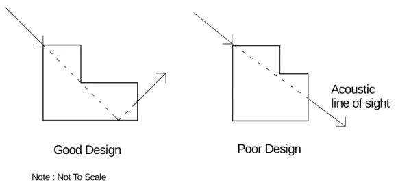
(3) Selection of noise rating of the HVAC diffusers will be based on the actual design airflow, and Project Co will not presume that they will meet their noise rating at any airflow. Project Co will take into consideration the total number of diffusers understanding that each doubling of the number of diffusers increases the overall noise level by 3dB. Diffusers must be selected to be 10 NC points lower than the NC rating for the room. (4) Care will be taken in locating return air elbows in systems that are not ducted.
Acoustically lined return air elbows must be located in non-critical acoustical walls (i.e. walls with doors, typically), must contain minimum 25 mm thick acoustic insulation and must be designed to block the line of sight through the elbow as per the “Good Design” shown in Figure 1 below.
Acoustic Elbows - Minimum Acoustic Requirements
Note : Not To Scale
Good Design
Poor Design
Acoustic
line of sight
Figure 1: Design considerations for acoustic elbows.
(5) The return air grilles in the rooms will be located an optimum distance from the return air elbow to reduce the potential for cross-talk.
(6) It is essential that all noise-producing HVAC equipment including mixing boxes, fan powered mixing boxes, and fan coil units be located outside the UBC Videoconference Rooms and not within the ceiling plenum space.
(c) Sound Isolation – Interior
(1) One of the key issues is achieving adequate sound isolation between the UBC
Videoconference Rooms and adjacent spaces. The adjacent spaces may include but are not limited to similar distance learning spaces, meeting rooms, lecture rooms, washrooms, corridors etc.
(2) In order to achieve the proper sound isolation, all perimeter walls of the UBC
Videoconference Rooms must achieve a Sound Transmission Class (STC) rating of STC 55. The laboratory STC ratings of all such perimeter walls must meet the requirements of ASTM E90-09: Standard Test Method for Laboratory Measurement of Airborne Sound Transmission Loss of Building Partitions and Elements, and must be based on test results obtained within the last 15 years and on results from an accredited and current test facility.
(3) Party walls must be full height. (4) If a stud wall design is used:
(5) Non-load bearing studs must be maximum 25 ga. and will be spaced at minimum 600 o.c. For all single stud walls, the lab STC rating is based on these details unless otherwise stated.
(6) Walls rated at STC 55 and higher must be double stud (i.e. two rows of studs and not staggered studs on a common base or complex single stud constructions). Stud ga. is not an issue for double stud walls.
(7) Resilient channel will not be used.
(8) Field Sound Transmission Class (FSTC), results meeting ASTM E336-09: Standard Test Method for Measurement of Airborne Sound Attenuation between Rooms in Buildings will be required for a random sample of partitions. For all such tests, results within 5 FSTC points of the lab STC rating for the partition in question must be achieved.
(9) In order to achieve the required minimum FSTC results, the following measures will be undertaken:
(A) Carefully seal all penetrations of the party walls.
(B) Active (i.e. those components containing moving air and/or water) ducts and pipes will not be grouted into party walls, but are free of the GWB, with a maximum 6mm gap caulked light tight with a non hardening mastic caulking material such as Tremco Acoustical Sealant or equivalent fire-rated sealant. (C) Seal all cable trays which pass through key party walls.
(D) Electrical boxes, etc. will not be installed back-to-back (i.e. have at least one complete insulated stud space separation).
(E) Caulk all floor and header tracks.
(F) Seal party wall/mullion details in such a way that the overall FSTC rating of the partition is not unduly compromised.
(d) Noise Isolation - Doors and other Entryways
(1) Where a single door (non-vestibule) opens to a noisy corridor, lobby or waiting area, a single width purpose-built acoustic door with a minimum STC 50 rating will be used. (2) For all other situations (including vestibule doors):
(A) Use solid core wood or filled metal doors.
(B) Ensure use of properly selected acoustic seals such as Pemko Type Silicon Seal S-88 plus Pemko Type 350 around the perimeter.
(C) Install automatic threshold closers similar to Pemko Type 430 which close over wood or metal sill plates which are levelled and caulked or grouted in place.
(D) Install all such doors/door systems so that light will not pass through the doors/door systems.
(e) Noise Isolation – Floor/Ceiling
(1) The location of the UBC Videoconference Rooms is important not only from a horizontal noise (i.e. not locating such rooms next to the main mechanical room, etc.) perspective, but also in terms of the floor/ceiling acoustic performance.
(2) The airborne noise isolation between vertically stacked spaces will meet minimum STC 50 rating.
(3) Impact noise including footfall noise, chair scraping etc can have a significant impact to the room acoustics. If there is occupied space above any of the UBC Videoconference Rooms, it may be necessary to include a full acoustic ceiling in the room to help control impact noise.
(4) While the floor/ceiling STC rating of a room might meet the required STC rating without an acoustic ceiling, impact noise might be problematic for rooms with exposed structural ceilings. Further, the room above must be carpeted or must have an Impact Insulation Class, IIC, (i.e. ASTM E492-09: Standard Test Method for Laboratory Measurement of Impact Sound Transmission Through Floor-Ceiling Assemblies Using the Tapping Machine) rating which exceeds 70. In the field, the rating must be FIIC 65, or higher (re ASTM E1007-04e1: Standard Test Method for Field Measurement of Tapping Machine Impact Sound Transmission Through Floor-Ceiling Assemblies and Associated Support Structures).
(f) Noise Isolation – Exterior Noise Impact
(1) For all UBC Videoconference Rooms, the maximum noise level due to exterior noise will be 35 dBA.
(2) To meet low ambient noise levels requirements, none of the UBC Videoconference Rooms will be located adjacent to mechanical or electrical rooms, exercise areas, washrooms, or elevators. To the extent possible, the UBC Videoconference Rooms will not be located next to exterior walls adjacent to busy roadways, airports, helicopter pads, major exterior equipment (such as cooling towers, chillers, emergency generator sets), or below roofs which contain major equipment or helicopter pads.
(g) Lighting
(1) 3500 degrees Kelvin colour temperature is required in the UBC Videoconference Rooms. Different lights/colour temperature will not be mixed.
(2) Fluorescent light ballasts will be remote mounted and integral transformers of low voltage lighting will be potted.
(3) The lighting dimmer controller will provide remote control access capability via serial or Ethernet protocol to control lighting ON/OFF and preset recall control from the AV control system.
(4) For rooms that have a presenter area at the front of the room, the low light area is defined as an area directly in front of the projection screens or flat panel displays, and
approximately 2000mm deep. The light level in these areas will be as low as possible to avoid washing out the image of the presenter. Such areas will be on a separate switch and will be non-dimmable.
(5) Light reflecting off projections screens and video display surfaces must be avoided in all of the UBC Videoconference Rooms.
(6) Lighting style and colour temperature will be carefully designed, such that the overhead lighting has a 45-degree angle of incidence; a colour temperature of 3500 K to eliminate “raccoon eyes” and dark shadows under the chin/nose and achieve the proper
reproduction of skin tones in the video images.
(7) For videoconferencing, perception (visibility, intelligibility and comfort) becomes an important factor of the design. Instructors/presenters will not feel comfortable in an overly illuminated or glaring environment and where they cannot see easily.
(8) The AV lighting system will be zoned on separate circuits and controls from the regular room lighting system.
(9) The reflected light from the walls will be slightly less than that from the faces of the individuals on camera. This is to provide some contrast while not creating exposure level difficulties for the camera.
(10) Fluorescent light ballasts will be remote mounted in an adjacent room to minimize noise in the room. If there are any low voltage lighting devices in the room with integral
transformers, they will be potted to prevent airborne or structure borne transformer noise from being introduced.
(11) For the lecture theatre/videoconference room and the medium videoconference/seminar room, the room lighting that falls on projection screen surfaces or video display surfaces will be separately switched.
(h) Interior Design
(1) The colour of the walls of the UBC Videoconference Rooms will be either grey or solid blue to provide visual definition to the presenter relative to the background. The purpose of the solid colour is to avoid adding unnecessary bandwidth to the video conferencing signal, and to avoid the reflected light from the background affecting colour quality of the images.
(2) The colour of the table and lectern surfaces will be either antique white or a light grey colour to allow the 45-degrees light to bounce off the surface and reflect upward. This helps to illuminate the faces of the presenters and eliminate the dark shadows under the chin/nose.
(3) The cameras require wall and/or ceiling positioning for appropriate image angles, and for complete visual coverage for all different educational usage scenarios. Specifically designated positions in the walls and/or ceilings are required to accommodate the cameras. The cameras also require appropriate housing for protection from theft and damage.
(i) Electrical Infrastructure Minimum Requirements
(1) Electrical infrastructure requirements for the videoconference system in each specific UBC Videoconference Room are described in Section 5 of this Appendix. Conduit sizes specified in Section 5 represent the minimum conduit size required to accommodate the videoconference equipment. Project Co will provide larger conduits if required to support other systems or equipment.
(2) Power receptacle requirements described in Section 5 are solely for the support of the AV systems and do not include any standard receptacles that may be required for purposes other than supporting the AV systems. Project Co will provide additional receptacles in the UBC Videoconference Rooms as required to support other systems or equipment. (j) Videoconference System Data and Telephone Outlet Minimum Requirements
(1) Data and telephone outlet requirements for the videoconference system in each specific UBC Videoconference Room are described in Section 5 of this Appendix. Data and telephone outlet requirements listed Section 5 are solely for the connectivity and support of the AV systems and do not include any standard outlets that may also be required for purposes other than supporting the AV systems. Project Co will provide additional outlets in the UBC Videoconference Rooms if required to support other systems or equipment. (2) In this Appendix:
(A) “AV Data outlet” means a data outlet connect to the UBC DMP-AV videoconferencing subnet; and
(B) “Regular Data outlet” means a data outlet connect to the UBC DMP-AV support subnet.
5. ROOM SPECIFIC REQUIREMENTS
5.1 Lecture Theatre/Videoconference Room - 120 seat (a) Architectural
(1) The lecture theatre/videoconference room will be a single contiguous space, and will not be sub-dividable.
(2) The minimum required room size for the lecture theatre/videoconference room is as specified in the Clinical Specification.
(3) Requirements for entrances to the lecture theatre/videoconference room are set out in the Clinical Specification.
(4) The side walls to front/back wall layout aspect ratio of the lecture theatre/videoconference room will be 1:1.02
(5) As per Appendix 2E [Equipment and Furniture], provide fixed benches as required for the lecture theatre/videoconference room that meet or exceed the specifications set out in the Equipment Data Sheets (refer to Equipment Number UBC 24). Without limiting Project Co’s obligations under Section 5.3 of Schedule 2 [Design and Construction Protocols], Project Co will submit shop drawings of the benches for review by UBC prior to installation.
(6) The lecture theatre/videoconference room will have three windows from the projection room. The window characteristics will be as specified in Sections 5.2(a)(4) through 5.2(a)(10).
(7) The lecture theatre will provide a projection path clear of any obtrusions from the projection both at the back of the lecture theatre to the front, with the bottom of the projection path to be a minimum of 2000mm AFF (above finished floor) at any point along the path.
(8) The lecture theatre will have two permanently-mounted, side-by-side projection screens located at the front wall. The projection screens will be made of Level 5 drywall plaster with a smooth finish. The projection screens will be coated with projection surface paint. The projection surface will be even and clean.
(9) The projection surfaces will be painted with a suitable paint, providing a matte white finish and a light reflection of a minimum 1.1.
(10) The projection screens will have dimensions 5700mm wide x 3200mm high (16:9 aspect ratio).
(12) The lecture theatre front wall will be no less than 5400mm high from the finished floor to the finished ceiling to accommodate the projection screens, the required clearance below the screens, and a small clearance above the screens.
(13) The projection screens will be at a horizontal angle of approximately 4.8 degrees, with the angle to be confirmed as part of the design process described in Section 5.3 of Schedule 2 [Design and Construction Protocols]. The projection screens will be aligned to be parallel with the projection room windows.
(14) The horizontal distance from the projection screens to the closest viewer seated in the front row will be greater than 1.05 times the single image screen width. See reference design drawing # 14.3.
(15) Ratio of the distance from the projection screens to the most distant viewer in the lecture theatre/videoconference room to screen height will not exceed a factor of 6.7 (distance to most distant viewer, MDV, divided by a single screen height, SH) for 95% of all seats. A maximum of 5% or 6 seats may be at a maximum MDV to SH factor of 7.2.
(16) The horizontal viewing angle will be up to a maximum of 60 degrees of axis for 95% of all audience seats. Up to 5% or 6 seats may be up to a maximum of 100 degrees horizontal viewing angle.
(17) The vertical viewing angle will be up to a maximum of 30 degrees for 95% of all audience seats. Up to 5%, or 6 audience seats may be up to a maximum vertical viewing angle of 37 degrees.
(18) The front wall will provide a minimum of 1200mm to the left and the right of the two projection screens for the wall mounted playback speakers. Speaker placement will be coordinated as part of the design process described in Section 5.3 of Schedule 2 [Design and Construction Protocols].
(19) The wall mounted playback speakers will be mounted at approximately 4000mm AFF. The mount locations will be equipped with plywood backing of a minimum of 1200mm x 1200mm in size, to support a minimum of 200 pounds.
(20) Provide a fixed lectern that meets or exceeds the specifications set out in the Equipment Data Sheets (refer to Equipment Number UBC 20). Without limiting Project Co’s
obligations under Section 5.3 of Schedule 2 [Design and Construction Protocols], Project Co will submit shop drawings of the lectern for review by UBC prior to installation. (21) The lectern will be located just to the right (stage right/house left) of the lecture theatre
centre line.
(22) The distance from the front wall to the lectern in the lecture theatre/videoconference room will be no less than 1600mm.
(23) The distance from the lectern to the front row of audience/student tables will be a minimum of 2400mm.
(24) The architectural design will allow for an audience camera to be located on the house right (stage left) wall. The camera location will be 2500mm above stage finished floor, and set back by 6000mm from the front wall corner.
(25) The front wall will accommodate a wall-mounted audience camera just below the projection screens.
(26) Provide the lecture theatre with a millwork housing for the confidence monitors, located at the front of the first audience seating/table row. Project Co will design and construct the confidence monitor housing to meet or exceed the specifications set out in the Equipment Data Sheets (refer to Equipment Number UBC 23). Without limiting Project Co’s
obligations under Section 5.3 of Schedule 2 [Design and Construction Protocols], Project Co will submit shop drawings of the confidence monitor housing for review by UBC prior to installation.
(b) Interior Acoustics
(1) Concave curved wall and ceiling surfaces focus sound. The larger the curved wall section, the broader the bandwidth of the focusing. Any concave curved surface must be treated with suitable broadband acoustic treatment to absorb or diffuse the sound wavefront. (2) The 100% occupied reverberation time will not exceed 0.6 seconds (mid-band), and the
70% occupied reverberation time will not exceed 0.7 seconds (mid-band), in the lecture theatre/videoconference room.
(3) The lecture theatre/videoconference room may require a full or partial acoustic ceiling in order to meet the reverberation time criterion of Section (2) above. If an acoustic ceiling is required, it will adhere to requirements described in Section 4.5(a)(5).
(c) Noise Isolation - Entry Vestibules
(1) The lecture theatre/videoconference room entry vestibules must be carpeted and must contain acoustic ceilings with a minimum Noise Reduction Coefficient, NRC, of 0.70. (2) The lecture theatre/videoconference room doors will be solid core wood or filled metal and
properly fitted to affect a reasonably good perimeter seal and be cut close to the carpet. (d) AV Systems Electrical Infrastructure Minimum Requirements
(1) The lecture theatre will be equipped with a suitable conduit/cable-tray and back-box infrastructure to support the low voltage AV system connectivity requirements, as outlined below.
(2) Four 27mm conduits and two 54mm conduits will connect the lectern location with the projection room equipment rack location (home run). The conduits will be stubbed into the lectern from below.
(3) One 27mm conduit will connect the audience camera location at the lecture theatre front wall with the projection room equipment rack location (home run). The conduit end at the camera location will terminate into a recessed, 87mm deep single gang box mounted at approximately 1900mm AFF at the lecture theatre front wall. The audience camera back box will be located at the horizontal centre of the lecture theatre front wall.
(4) Three 54mm rigid conduits will connect the confidence monitor millwork location with the projection room equipment rack location (home run). The conduit end at the confidence monitor millwork location will terminate into a recessed, 87mm deep four gang box mounted inside the confidence monitor millwork.
(5) One 27mm conduit will connect the side camera location at the lecture theatre side wall with the projection room equipment rack location (home run). The conduit end at the camera location will terminate into a recessed, 87mm deep single gang box mounted at approximately 2500mm AFF at the lecture theatre side wall.
(6) Two 27mm conduits will connect the playback speaker locations at the lecture theatre front wall with the projection room equipment rack location (home run). The conduit end at the playback speaker location will terminate into recessed, single gang boxes mounted at approximately 4000mm AFF at the lecture theatre front wall. The playback speaker back boxes will be located 1000mm to the left and to the right of the projection screen locations.
(7) One 21mm conduit home run will connect the projection room AV equipment rack location to each of four ceiling loudspeaker zones (Front row, second row, third row and fourth row). All four zones will be laid out in the same direction as the audience seating/tables. The conduit will connect the speakers for a total of up to 8 speakers per zone.
(8) Install suitable sized loudspeaker cable to connect the audio amplifier mounted in the AV equipment racks located in the projection room to each ceiling speaker in the four zones. Provide a daisy chain connection to each of the loudspeakers in each of the four zones. Pull wiring into conduits.
(9) For all ceiling speakers to be mounted in GWB (dry wall board), provide a suitable plaster ring for Tannoy CMS-401DCe loudspeakers, part # 80001 4180.
(10) One 54mm rigid conduit will connect the projection room equipment racks with the location of the lecture theatre lighting system dimmer controller.
(11) One 54 mm rigid conduit will connect the projection room equipment racks with a data/communication closet on the same floor as the lecture theatre.
(12) Two 54mm rigid conduits will connect the projection room equipment racks with either end of each audience desk in the lecture theatre. The conduits will be connected into a vertical cable tray located inside the table leg connecting the floor with the audience desk table surface.
(13) The audience desks will have under-desk mounted, covered cable trays, with hinged tray covers, connecting the vertical cable tray with each audience microphone location. (14) Where possible, adequately sized basket cable tray may be used to combine individual
conduit runs. Any such cable trays must provide suitable compartments to separate video, audio and control signal wiring.
(15) Conduit runs with more than 90 degree turns require cable pull boxes to be inserted in the proper locations.
(16) All conduits require being equipped with pull-strings to allow for the low voltage wiring being pulled in.
(e) AV Systems Power Loads and Minimum Requirements
(1) The lecture theatre has the following power loads for the audiovisual and videoconference systems.
(A) The AC load requirement for the two confidence monitor displays is 1,600 watts (800 watts per display) in operation and 200 watts at idle.
(B) The AC load requirement for the equipment mounted in the lectern is 3,000 watts in operation and 200 watts at idle.
(f) Provide the following power receptacles for the support of the audiovisual systems:
(1) Two 15 amp Quad AC receptacles with one 120V 15Amp circuit per quad receptacle, mounted inside the lectern millwork.
(2) One 15 amp Dual AC receptacle with its own 120V 15Amp circuit, mounted at the lectern face plate.
(3) Two 15 amp Quad AC receptacles with one 120V 15Amp circuit per quad receptacle, mounted inside the confidence monitor millwork.
(4) One 15 amp Dual flip-open AC receptacle for each pair of audience seats. These receptacles will be recessed into the audience table surfaces.
(g) All AC receptacles to be utilized for the AV systems will have a very low impedance connection to the ground plane of the Building.
(1) Lighting
(A) The instructor area as identified in the reference design lighting drawings will have an illuminated level of 80 foot candles at face level, with lighting reflecting off the lectern surface at an approximate 15 – 20 degree angle, and will be dimmable on a separate switch.
(B) The audience lighting area as identified in the reference design lighting
requirements drawings will have illumination requirements of 50 – 60 foot candles at face level with lighting reflecting off the table surfaces at an approximate 15 – 20 degree angle. The lighting will be dimmable, zoned on a separate switch. (h) Videoconference System Data and Telephone Outlet Minimum Requirements
(1) Provide:
(A) One Regular Data outlet in the lectern for instructor PC, terminated outlet inside lectern.
(B) One AV Data outlet inside lectern for VNC, terminated outlet inside lectern. (C) One Regular Data outlet for the AV Control System inside lectern, terminated
outlet inside lectern.
(D) Three Regular Data outlet at the lectern faceplate, terminated millwork mount outlet.
(E) One VoIP phone outlet at the lectern faceplate, terminated millwork mount outlet. (i) Interior Design
(1) The front wall of the lecture theatre will be finished in a uniform, matte, light grey color to provide a suitable video camera backdrop.
(2) Videoconference acoustic echo cancelling relies on minimizing the number of
loudspeakers in the room. Loudspeaker positioning will be based on providing optimum uniformity and coverage. Grilles or speaker covers must be acoustically transparent and free of obstructions larger than 19mm square as these create shadows in the coverage area.
(3) The lecture theatre/videoconference room will have speech reinforcement loudspeakers distributed on the ceiling to provide uniform speech levels for general instruction
purposes. This is necessary to eliminate the problem of having excessive sound levels at the front of the room in order to achieve adequate sound levels at the back. The lecture theatre/videoconference room will have flush mount ceiling speakers at locations
determined by UBC during the design process based on UBC’s acoustical modeling of the architectural design.
(4) Heavily articulated ceilings will be avoided as they may require the use of surface mount ceiling speakers to achieve the required coverage.
5.2 Projection Room (a) Architectural
(1) The minimum required room size for the projection booth is as specified in the Clinical Specifications.
(2) The side walls of the projection room will be at least 2600mm deep. The room will be at least 6500mm wide.
(3) The projection room will be centered on the center-line of the lecture theatre. (4) The projection room will have a total of 3 windows into the lecture
theatre/videoconference room: 2 projection windows, and 1 operator window.
(5) It is critical that there be a clear projection path between the projection windows and the projection screens at the front of the lecture theatre/videoconference room. For example, suspended lighting fixtures in the lecture theatre must be taken into account.
(6) The projection windows will be at least 450mm high x 750mm wide each.
(7) There will be a clearance of 2100mm from the finished floor to the bottom of the projection windows.
(8) The projection windows will utilize glare-free glass, and there will be no glass seams within the light path of the projectors.
(9) The operator position window must provide a clear sightline to the front of the lecture theatre/videoconference room. This window will utilize one-way, see-through security glass. The window will be located approximately 1000mm AFF, and be at least 600mm high x800mm wide.
(10) The projection room windows do not require blackout blinds.
(11) Provide all necessary structural support for the wall mount equipment such as the AV equipment racks and the video monitoring displays.
(b) Interior Acoustics
(1) Sections 4.5(a)(2) through 4.5(a)(5) of this Appendix do not apply to the projection room. (2) A full suspended acoustic tile ceiling will be included in the room with minimum NRC 0.70
(c) Background Noise
(1) There will be maximum airflow of 2.5 m/s at the face of the supply air diffusers and 3 m/s at the face of the return air grille.
(2) The NC rating for the projection room is NC35. (d) AV Systems Electrical Infrastructure Minimum Requirements
(1) The projection room will be equipped with an overhead cable tray running around the perimeter of the room, mounted at 2300mm AFF. All conduits connecting into the projection room will terminate into the overhead cable tray. The cable tray will be equipped with three separate compartments.
(2) The cable tray will provide three 100x 50mm sleeves into the equipment racks in the projection room.
(3) One 54mm and one 27mm rigid conduit will connect the projection room equipment racks with the projection room operator position. The conduit end at the operator desk location will terminate into a recessed, 87mm deep triple gang box mounted at approximately 900mm AFF. The operator desk back box location will be located at the projection room wall, adjacent to the lecture theatre, and be located near the desk location by the operator window.
(4) Two 54mm rigid conduits will connect the projection room equipment racks with the Building low voltage cable tray.
(e) AV Systems Power Loads and Minimum Requirements
(1) The projection room has the following power loads for the audiovisual and videoconference systems:
(A) The AC load requirement for the equipment racks in the projection room is 13,500 watts (4,500 watts per rack) in operation and 1200 watts at idle.
(B) The AC load requirement for the ceiling mounted projectors in the projection room is 2,400 watts (1,200 watts per projector) in operation and 200 watts at idle (2) Provide the following power receptacles for the support of the audiovisual systems:
(A) One 15 amp Dual AC receptacle, with its own 120V/15amp circuit, ceiling or wall mount near the left projector location in the projection room.
(B) One 15 amp Dual AC receptacle with its own 120V 15Amp circuit wall mount for the instructor camera near the left projection window location in the projection room.
(C) One 15 amp Dual AC receptacle with its own 120V 15Amp circuit ceiling or wall mount near the right projector location in the projection room.
(D) Six 15 amp Quad AC receptacles (two per rack), with one 120V/15Amp circuit per quad receptacle, mounted either below the overhead cable tray or inside the AV equipment racks inside the projection room.
(3) All AC receptacles to be utilized for the AV systems will have a very low impedance connection to the ground plane of the Building.
(4) All AC receptacles for the AV equipment racks require the provision of a ground point termination bar.
(f) Videoconference System Data and Telephone Outlet Minimum Requirements (1) Provide:
(A) One Regular Data outlet at the operator position, terminated outlet at operator desk location (1 outlet total).
(B) One VoIP/analog phone outlet at the operator position, terminated outlet at operator desk location (1 outlet total).
(C) 6 AV Data outlets for the 3 AV racks; 2 outlets terminated inside each rack (6 outlets total).
(D) 6 Regular Data outlets for the 3 AV racks; 2 outlets terminated inside each rack (6 outlets total).
(E) One Analog Phone outlet for the AV racks; terminated outlet inside AV equipment rack (1 outlet total).
5.3 Medium Videoconference/Seminar Room (35 Seats) (a) Architectural
(1) The minimum required room size for the medium videoconference/seminar room is as specified in the Clinical Specification.
(2) Requirements for entrances to the medium videoconference/seminar room are set out in the Clinical Specification.
(3) The side walls to front/back wall layout aspect ratio of the medium videoconference/seminar room will be 1:1.4 to 1.6.
(4) As per Appendix 2E [Equipment and Furniture], provide fixed audience tables as required for the medium videoconference/seminar room that meet or exceed the specifications set
out in the Equipment Data Sheets (refer to Equipment Number UBC 21). Without limiting Project Co’s obligations under Section 5.3 of Schedule 2 [Design and Construction Protocols], Project Co will submit shop drawings of the audience tables for review by UBC prior to installation.
(5) The medium videoconference/seminar room will have one window joining the central videoconference operator/rack room. See Sections 5.7(a)(5) through 5.7(a)(8) for window requirements.
(6) As per Appendix 2E [Equipment and Furniture], provide a fixed lectern that meets or exceeds the specifications set out in the Equipment Data Sheets (refer to Equipment Number UBC 20). Without limiting Project Co’s obligations under Section 5.3 of Schedule 2 [Design and Construction Protocols], Project Co will submit shop drawings of the lectern for review by UBC prior to installation.
(7) The lectern is to be placed directly adjacent to the medium videoconference/seminar room side wall to permit electrical and low voltage wiring services to be connected directly from the wall space into the lectern.
(8) The lectern is to be placed on the stage right side of the medium videoconference/seminar room (or house left).
(9) The horizontal distance from the front wall to the lectern in the medium videoconference/seminar room will be no less than 1500mm.
(10) The horizontal distance from the wall mount flat-panel displays on the front wall to the first audience seating row will be 2300mm minimum.
(11) The entire front wall of the medium videoconference/seminar room will be equipped with floor to ceiling plywood backing to permit secure mounting of the three displays, camera and speakers with a total combined weight of 2,000 pounds.
(12) The entire back wall of the medium videoconference/seminar room will be equipped with floor to ceiling plywood backing to permit secure mounting of the three confidence monitor displays with a total combined weight of 600 pounds.
(13) The ratio of the distance from the main displays to the most distant viewer, to the single image screen height in the medium videoconference/seminar room will not exceed a factor of 6.7 (distance to most distant viewer, MDV, divided by single image screen Height, SH) for at least 90% or 31 seats. Up to a maximum of 10% or 4 seats can be at a MDV to SH ratio of up to 7.2.
(14) The horizontal viewing angle from the audience seats to the front wall displays will be up to a maximum of 60 degrees of axis for 95% of all audience seats. Up to 5% or 2 seats can be at a maximum of 100 degrees horizontal viewing angle.
(15) The vertical viewing angle will be up to a maximum of 30 degrees for 90%, or 31, of all audience seats. Up to 10%, or 4, audience seats may be up to a maximum vertical viewing angle of 37 degrees.
(16) The wall space behind the lectern from the corner of the front/presentation wall to a distance of 3100mm along the wall will be used as the instructor camera backdrop and will be clear of any electrical outlets and any other services.
(b) Interior Acoustics
(1) The medium videoconference/seminar room will have an acoustic ceiling which meets the requirements in Section 4.5(a)(5).
(2) For the medium videoconference/seminar room, the 100% occupied reverberation time will not exceed 0.5 seconds (mid-band), and the 70% occupied reverberation time will not exceed 0.6 seconds (mid-band), to provide good speech intelligibility and to minimize artefacts in the conference audio.
(c) AV Systems Electrical Infrastructure Minimum Requirements
(1) The medium videoconference/seminar room will be equipped with a suitable conduit/cable-tray and back-box infrastructure to support the low voltage AV system connectivity requirements, as outlined below.
(2) Four 27mm conduits and two 54mm conduits will connect the lectern location with the equipment rack location (home run) in the central videoconference operator/rack room. The conduits will be stubbed into the lectern from below from the floor, or from the side through the wall.
(3) One 27mm conduit will connect the audience camera location at the front wall with the equipment rack location in the central videoconference operator/rack room. The conduit end at the camera location will terminate into a recessed, 87mm deep single gang box mounted at approximately 2300mm AFF at the front wall. The audience camera back box location will be located at 3100mm from the stage right (house left) corner of the front wall.
(4) Three 54mm rigid conduits and three 21mm conduits will connect the three front wall mount main display locations with the equipment rack location in the central
videoconference operator/rack room. The conduit end at the main display locations will terminate into a recessed, 87mm deep triple gang wide box mounted on the front wall at 2300mm AFF. The horizontal locations of the three boxes will be 5000mm, 7000mm and 8900mm respectively, measured from the stage right (house left) corner of the front wall. (5) Three 54mm rigid conduits and three 21mm conduits will connect the three back wall
mount confidence display locations with the equipment rack location in the central
will terminate into a recessed, 87mm deep triple gang wide box mounted on the room back wall at 2500mm AFF. The horizontal locations of the three boxes will be 800mm, 1500mm and 2300mm respectively measured from the house right (stage left) corner of the back wall.
(6) One 27mm conduit will connect the instructor camera location at the back wall with the equipment rack location (home run) in the central videoconference operator/rack room. The conduit end at the camera location will terminate into a recessed, 87mm deep single gang box mounted at approximately 2500mm AFF at the back wall, 3000mm from the house left corner (stage left).
(7) Two 27mm conduits will connect the playback speaker locations at the front wall with the equipment rack location (home run) in the central videoconference operator/rack room. The conduit end at the playback speaker location will terminate into a recessed, single gang box mounted at app 2500 AFF at the front wall. The two playback speaker back boxes will be located 3200mm from the stage right corner, and 1800mm from the stage left corner of the room front wall respectively.
(8) One 21mm conduit home run will connect the central videoconference operator/rack room equipment racks to each of three ceiling loudspeaker zones (front row, second row and third row). Each row will be laid out in the same direction as the audience seating/tables. The conduit will connect the speakers in each zone up to a maximum of 6 speakers per zone.
(9) Install one loudspeaker suitable sized cable to connect the audio amplifier mounted in the equipment rack located in the central videoconference operator/rack room to the ceiling speakers in three zones. Provide a daisy chain connection to each of the maximum of 6 loudspeakers in each of the three zones. Pull wiring into conduits.
(10) For all ceiling speakers scheduled to be mounted in GWB, provide a plaster ring for Tannoy CMS-401DCe loudspeakers, part # 80001 4180.
(11) One 54mm rigid conduit will connect the equipment racks located in the central videoconference operator/rack room with the location of the medium
videoconference/seminar room lighting system dimmer controller.
(12) One 54 mm rigid conduit will connect the equipment racks located in the central
videoconference operator/rack room with a data/communications closet on the same floor. (13) Two 54mm rigid conduits will connect the equipment racks to both ends of each audience
desks in the medium videoconference/seminar room. The conduits will be connected into a vertical cable tray located inside the table leg connecting the floor with the audience desk table surface.
(14) The audience tables will have under-desk mount covered cable trays, with hinged tray covers connecting the vertical cable tray with each audience microphone location.
(15) Where possible, adequately sized basket cable tray will be used to combine individual conduit runs. Any such cable trays must provide suitable compartments to separate video, audio and control signal wiring.
(16) Conduit runs with more than 90 degree turns require cable pull boxes to be inserted in the proper locations
(17) All conduits require being equipped with pull-strings to allow for the low voltage wiring being pulled in.
(d) AV Systems Power Loads and Minimum Requirements
(1) The medium videoconference/seminar room has the following power loads for the audiovisual and videoconference systems:
(A) The AC load requirement for the wall mounted displays is 5,000 watts in operation and 300 watts at idle
(B) The AC load requirement for the equipment mounted in the lectern is 3,000 watts in operation and 200 watts at idle
(2) Provide the following power receptacles:
(A) Two 15 amp Quad AC receptacles with one 120V 15Amp circuit per quad receptacle, mounted inside the lectern millwork.
(B) One 15 amp Dual AC receptacle with its own 120V 15Amp circuit, mounted at the lectern face plate.
(C) Three 15 amp Dual AC receptacle, each with its own 120V/15amp circuit, wall mount next to the back boxes for the main displays at the front wall.
(D) Three 15 amp Dual AC receptacle, each with its own 120V/15amp circuit, wall mount next to the back boxes for the confidence displays at the back wall. (E) One 15 amp Dual AC receptacle with its own 120V 15Amp circuit wall mount next
to the instructor camera back box on the back wall.
(F) One 15 amp Dual AC receptacle with its own 120V 15Amp circuit wall mount next to the audience camera back box on the front wall.
(G) One 15 amp Dual flip-open AC receptacle for each pair of audience seats. These receptacles will be recessed into the audience table surfaces.
(3) All AC receptacles to be utilized for the AV systems will have a very low impedance connection to the ground plane of the Building.
(e) Lighting
(1) The instructor area (as identified in reference drawing #6.0) will have an illuminated level of 80 foot candles at face level, with lighting reflecting off the lectern surface at
approximately 15 – 20 degree angle, and will be dimmable on a separate switch. (2) The audience lighting area (as identified in reference drawing #6.0) will be have
illumination requirement of 50 – 60 foot candles at face level, with lighting reflecting off the table surfaces at an approximate 15 – 20 degree angle. The lighting will be dimmable, zoned on a separate switch.
(f) Videoconference System Data and Telephone Outlet Minimum Requirements (1) Provide:
(A) One Regular Data outlet in the lectern for instructor PC, terminated outlet inside lectern.
(B) One AV Data outlet inside lectern for VNC, terminated outlet inside lectern. (C) One Regular Data outlet for the Crestron inside lectern, terminated outlet inside
lectern.
(D) Three Regular Data outlet at the lectern faceplate, terminated millwork mount outlet.
(E) One VoIP phone outlet at the lectern faceplate, terminated millwork mount outlet. 5.4 Interior Design
(a) The front wall will be finished in a uniform matte, light grey finish, to provide a suitable video camera backdrop.
5.5 Small Videoconference/Seminar Room (16 seats) (a) Architectural
(1) The minimum room size for the small videoconference/seminar room is as specified in the Clinical Specification.
(2) Requirements for entrances to the small videoconference/seminar room are set out in the Clinical Specification.
(3) The small videoconference/seminar room side walls to front/back wall layout aspect ratio will be 1:1.13.
(4) The Authority intends to provide loose participant tables for the small
U-shape with room for at least 6 seats at the bottom of the ‘U’ (the ‘head’ of the table). The ‘U’ will open to the front of the room.
(5) The closest distance from the front wall to the participant table will be no less than 1600mm.
(6) The entire width of the front wall will be equipped with floor to ceiling plywood backing to permit secure mounting of the two displays, camera and speakers with a total combined weight of 600 pounds.
(7) Ratio of distance from displays to most distant viewer, to screen height, will not exceed a factor of 6.7 (distance from display to most distant viewer, MDV, divided by a screen height, SH) for all seats. The distances will be measured from the centre of the display on the far end to the most distant viewer to determine the MDV.
(8) The horizontal viewing angle for all seats will not exceed 60 degrees for the 2 front wall mount displays.
(b) Interior Acoustics
(1) The small videoconference/seminar room will have an acoustic ceiling which meets the requirements of Section 4.5(a)(5).
(2) For the small seminar room the reverberation time will not exceed 0.5 seconds (mid-band), to minimize artefacts in the conference audio.
(c) AV Systems Electrical Infrastructure Minimum Requirements
(1) The small videoconference/seminar room will be equipped with a conduit/cable-tray and back-box infrastructure to support the low voltage AV system connectivity requirements, as outlined below.
(2) One 300mm x 300mm AV pull-box will be located at the centre of the front wall at 300mm AFF, serving as the room AV conduit home run.
(3) Three 27mm conduits will connect the ‘chair’ and ‘co-chair’ positions located at the centre of the ‘head’ of the table via three recessed floor boxes with the AV pull–box (home run). (4) The three floor boxes will provide the equivalent of two single gang sized openings
dedicated to low voltage AV, and provide suitable space for cable management.
(5) One 27mm conduit will connect the camera location at the front wall with the AV pull-box (home run). The conduit end at the camera location will terminate into a recessed, 87mm deep single gang box mounted at approximately 1600mm AFF at the centre of the front wall.
(6) Two 54mm rigid conduits and two 21mm conduits will connect the two front wall mount display locations with the AV pull-box location. The conduit end at the main display locations will terminate into a recessed, 87mm deep triple gang wide box mounted on the front wall at 1600mm AFF. The horizontal locations of the two boxes will be 3000 and 5000mm respectively measured from the stage right (house left) corner of the front wall. (7) Two 27mm conduits will connect the playback speaker locations at the front wall with the
AV pull-box. The conduit end at the playback speaker locations will terminate into recessed, single gang boxes mounted at approximately 1600 AFF at the front wall. The two playback speaker back boxes will be located 1500mm from the stage right corner and 1500mm from the stage left corner of the room front wall respectively.
(8) One 54mm rigid conduit will connect the AV pull-box in the small
videoconference/seminar room with the location of the small videoconference/seminar room lighting system dimmer controller.
(9) One 54 mm rigid conduit will connect the AV pull-box with the location of a
data/communications closet on the same floor as the small videoconference/seminar room.
(10) One 54mm rigid conduit will connect the AV pull-box with the building low voltage cable tray. In the absence of a building-wide low voltage cable tray, provide a 54mm rigid conduit connecting the AV pull-box with the central videoconference operator/rack room. (11) Where possible, adequately sized basket cable tray may be used to combine individual
conduit runs. Any such cable trays must provide suitable compartments to separate video, audio and control signal wiring.
(12) Conduit runs with more than 90 degree turns require cable pull boxes to be inserted in the proper locations.
(13) All conduits require being equipped with pull-strings to allow for the low voltage wiring being pulled in.
(d) AV Systems Power Loads and Minimum Requirements
(1) The AC load from the AV equipment located in the small videoconference/seminar room is 3000 watts in operation and 200 watts at idle.
(2) Provide the following power receptacles:
(A) One 15 amp Quad AC receptacles with one 120V 15Amp circuit per quad receptacle, mounted next to the AV pull box
(B) Two 15 amp Dual AC receptacle, each with its own 120V/15amp circuit, wall mount next to the back boxes for the main displays at the front wall.
(C) One 15 amp Dual AC receptacle with its own 120V 15Amp circuit wall mount for the camera next to the camera back box on the back wall.
(D) Three floor mount, recessed dual AC receptacles, one approximately at the centre of the bottom of the ‘U’-shaped table, and one at each end of the top of the table.
(e) Lighting
(1) Section 4.5(g)(4) of this Appendix does not apply to the small videoconference/seminar room since the room does not have a presenter area at the front.
(2) The participant area will have an illuminated level of 70 – 80 foot candles at face level, with lighting reflecting off the table surface at an approximate 15 – 20 degree angle. The lighting will be dimmable, zoned on a separate switch.
(f) Videoconference System Data and Telephone Outlet Minimum Requirements (1) Provide:
(A) Two AV Data outlets in AV millwork, terminated outlet inside AV millwork. (B) Two Regular Data outlets in AV millwork, terminated outlet inside AV millwork. (C) Two Regular IP outlets in the AV millwork, terminated outlet at millwork faceplate. (D) One VoIP phone outlet at the millwork faceplate, terminated millwork mount
outlet.
(E) One Analog Phone outlet in the AV millwork, terminated outlet inside AV millwork. (g) Interior Design
(1) The small videoconference/seminar room walls will be finished in uniform matte, light grey finish, to provide a suitable video camera backdrop.
5.6 Small Videoconference Room (8 Seats) (a) Architectural
(1) The minimum required room size for the small videoconference room is as specified in the Clinical Specification.
(2) Requirements for entrances to the small videoconference room are set out in the Clinical Specification.