UPnP™ Device Architecture 1.1
Document Revision Date: October 15, 2008
© 2008 Contributing Members of the UPnP Forum. All rights reserved. See
http://www.upnp.org/info/cpyright.asp for more information.
Authors*
Company
Alan Presser
AllegroSoft
Lee Farrell
Canon
Devon Kemp
Canon
William Lupton
Conexant
Shinichi Tsuruyama
Epson
Shivaun Albright
HP
Andrew Donoho
IBM
John Ritchie
Intel
Bryan Roe
Intel
Mark Walker
Intel
Toby Nixon
Microsoft
Colleen Evans
Microsoft
Henry Rawas
Microsoft
Trevor Freeman
Microsoft
Joonyoung Park
Motorola
Cathy Chan
Nokia
Franklin Reynolds
Nokia
Jose Costa-Requena
Nokia
Yinghua Ye
Nokia
Tom McGee
Philips
Geert Knapen
Philips
Maarten Bodlaender
Philips
Jarno Guidi
Philips
Lex Heerink
Philips
John Gildred
Pioneer
Alan Messer
Samsung
YoonSoo Kim
Samsung
Markus Wischy
Siemens
Andrew Fiddian-Green
Siemens
Bruce Fairman
Sony
Jonathan Tourzan
Sony
John Fuller
Sony
*Note: The UPnP Forum in no way guarantees the accuracy or completeness of this author list and in no way implies any rights for or support from those members listed. This list is not the specifications’ contributor list that is kept on the UPnP
Table of Contents
List of Tables ... v
List of Figures ... vi
i
Introduction ... 1
i.1
What is UPnP™ Technology? ... 1
i.2
UPnP™ Forum ... 1
i.3
In this document ... 2
i.4
Audience ... 5
i.5
Conformance terminology ... 5
i.6
Acronyms ... 6
i.7
Glossary ... 6
i.8
References and resources ... 7
0
Addressing ... 8
0.1
Determining whether to use Auto-IP ... 8
0.2
Choosing an address ... 8
0.3
Testing the address ... 9
0.4
Forwarding rules ... 10
0.5
Periodic checking for dynamic address availability ... 10
0.6
Device naming and DNS interaction ... 10
0.7
Name to IP address resolution ... 11
0.8
References ... 11
1
Discovery ... 12
1.1
SSDP message format ... 15
1.1.1
SSDP Start-line ... 16
1.1.2
SSDP message header fields ... 16
1.1.3
SSDP header field extensions ... 16
1.1.4
UUID format and RECOMMENDED generation algorithms ... 17
1.1.5
SSDP processing rules ... 17
1.2
Advertisement ... 17
1.2.1
Advertisement protocols and standards ... 18
1.2.2
Device available - NOTIFY with ssdp:alive ... 19
1.2.3
Device unavailable -- NOTIFY with ssdp:byebye... 25
1.2.4
Device Update – NOTIFY with ssdp:update ... 27
1.3
Search ... 29
1.3.1
Search protocols and standards ... 29
1.3.2
Search request with M-SEARCH ... 30
1.3.3
Search response ... 33
1.4
References ... 36
2
Description ... 37
2.1
Generic requirements on HTTP usage ... 40
2.2
Generic requirements on XML usage ... 43
2.4
UPnP Device Template ... 48
2.5
Service description ... 48
2.5.1
Defining and processing extended data types ... 55
2.5.2
String equivalents of extended data types ... 57
2.5.3
Generic requirements ... 58
2.5.4
Ordering of Elements ... 58
2.5.5
Versioning ... 59
2.6
UPnP Service Template ... 59
2.7
Non-standard vendor extensions and limitations ... 60
2.7.1
Placement of Additional Elements and Attributes ... 61
2.8
UPnP Device Schema ... 61
2.9
UPnP Service Schema ... 62
2.10
UPnP Datatype Schema ... 62
2.11
Retrieving a description using HTTP ... 62
2.12
References ... 65
3
Control ... 67
3.1
Control protocols ... 69
3.1.1
SOAP Profile ... 69
3.2
Actions ... 73
3.2.1
Action invocation ... 73
3.2.2
Action Response ... 76
3.2.3
UPnP Action Schema ... 79
3.2.4
Recommendations and additional requirements ... 79
3.2.5
Action error response ... 79
3.2.6
UPnP Error Schema ... 82
3.3
Query for variable ... 83
3.4
References ... 83
4
Eventing ... 84
4.1
Unicast eventing ... 85
4.1.1
Subscription ... 86
4.1.2
SUBSCRIBE with NT and CALLBACK ... 88
4.1.3
Renewing a subscription with SUBSCRIBE with SID ... 91
4.1.4
Canceling a subscription with UNSUBSCRIBE ... 93
4.2
Multicast Eventing ... 95
4.3
Event messages ... 96
4.3.1
Error Cases ... 97
4.3.2
Unicast eventing: Event messages: NOTIFY ... 97
4.3.3
Multicast Eventing: Event messages: NOTIFY ... 101
4.4
UPnP Event Schema ... 104
4.5
Augmenting the UPnP Device and Service Schemas ... 104
4.6
References ... 105
5
Presentation ... 106
A.1
Introduction ... 109
A.2
General Principles ... 109
A.2.1
Device operation ... 110
A.2.2
Control point operation ... 110
A.3
Addressing ... 110
A.3.1
Summary of boot/startup process ... 111
A.3.2
Short overview of protocol specified by RFC 2462 ... 111
A.4
Discovery ... 112
A.4.1
Advertisement ... 113
A.4.2
Advertisement: Device unavailable ... 114
A.4.3
Advertisement: Device update ... 114
A.4.4
Search ... 114
A.4.5
Search response ... 115
A.5
Description ... 115
A.6
Control ... 115
A.7
Eventing ... 115
A.8
Presentation ... 116
A.9
References ... 116
Appendix B.
Schemas ... 117
B.1
UPnP Device Schema ... 117
B.2
UPnP Service Schema ... 122
B.3
UPnP Control Schema ... 126
B.4
UPnP Error Schema ... 127
B.5
UPnP Event Schema ... 128
List of Tables
Table i-1:
Acronyms ... 6
Table 1-1:
Root device discovery messages ... 20
Table 1-2:
Embedded device discovery messages ... 20
Table 1-3:
Service discovery messages ... 20
Table 2-1:
Vendor extensions ... 60
Table 3-1:
SOAP 1.1 UPnP Profile ... 70
Table 3-2:
mustUnderstand
attribute ... 71
Table 3-3:
UPnP Defined Action error codes ... 82
Table 4-4:
HTTP Status Codes indicating a Subscription Error ... 91
Table 4-5:
HTTP Status Codes indicating a Resubscription Error ... 93
Table 4-6:
HTTP Status Codes indicating a Cancel Subscription Error ... 94
Table 4-7:
HTTP Status Codes indicating a Notify Error ... 101
List of Figures
Figure i-1:
Protocol stack ... 2
Figure 1-1:
Discovery architecture ... 13
Figure 1-2:
Advertisement protocol stack ... 19
Figure 1-3:
Initial and repeat announcements, no announcement spreading ... 21
Figure 1-4:
Initial and repeat announcements, message spreading of repeat announcements 21
Figure 1-5:
Search protocol stack ... 30
Figure 2-1:
Description architecture ... 37
Figure 2-2:
Description retrieval protocol stack ... 63
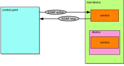
Figure 3-1:
Control architecture ... 67
Figure 3-2:
Control protocol stack ... 69
Figure 4-1:
Unicast eventing architecture ... 85
Figure 4-2:
Unicast eventing protocol stack ... 86
Figure 4-3:
Multicast eventing architecture ... 95
Figure 4-4:
Mulitcast eventing protocol stack ... 95
Figure 5-1:
Presentation architecture ... 106
i Introduction
[Informative]
i.1
What is UPnP™
1
Technology?
UPnP™ technology defines an architecture for pervasive peer-to-peer network connectivity of intelligent appliances, wireless devices, and PCs of all form factors. It is designed to bring easy-to-use, flexible, standards-based connectivity to ad-hoc or unmanaged networks whether in the home, in a small business, public spaces, or attached to the Internet. UPnP technology provides a distributed, open networking architecture that leverages TCP/IP and Web technologies to enable seamless proximity networking in addition to control and data transfer among networked devices.
The UPnP Device Architecture (UDA) is more than just a simple extension of the plug and play peripheral model. It is designed to support zero-configuration, "invisible" networking, and automatic discovery for a breadth of device categories from a wide range of vendors. This means a device can dynamically join a network, obtain an IP address, convey its capabilities, and learn about the presence and capabilities of other devices. Finally, a device can leave a network smoothly and automatically without leaving any unwanted state behind.
The technologies leveraged in the UPnP architecture include Internet protocols such as IP, TCP, UDP, HTTP, and XML. Like the Internet, contracts are based on wire protocols that are declarative, expressed in XML, and communicated via HTTP. Using Internet protocols is a strong choice for UDA because of its proven ability to span different physical media, to enable real world multiple-vendor interoperation, and to achieve synergy with the Internet and many home and office intranets. The UPnP architecture has been explicitly designed to accommodate these environments. Further, via bridging, UDA accommodates media running non-IP protocols when cost, technology, or legacy prevents the media or devices attached to it from running IP. What is "universal" about UPnP technology? No device drivers; common protocols are used instead. UPnP networking is media independent. UPnP devices can be implemented using any programming language, and on any operating system. The UPnP architecture does not specify or constrain the design of an API for applications; OS vendors may create APIs that suit their customers’ needs.
i.2
UPnP™ Forum
The UPnP Forum is an industry initiative designed to enable easy and robust connectivity among stand-alone devices and PCs from many different vendors. The UPnP Forum seeks to develop standards for describing device protocols and XML-based device schemas for the purpose of enabling device-to-device interoperability in a scalable, networked environment.
The UPnP Implementers Corporation (UIC) is comprised of UPnP Forum member companies across many industries that promote the adoption of uniform technical device interconnectivity standards and testing and certifying of these devices. The UIC
develops and administers the testing and certification process, administers the UPnP logo program, and provides information to UIC members and other interested parties regarding the certification of UPnP devices. The UPnP device certification process is open to any vendor who is a member of the UPnP Forum and UIC, has paid the UIC dues, and has devices that support UPnP functionality. For more information, see http://www.upnp-ic.org.
The UPnP Forum has set up working committees in specific areas of domain expertise. These working committees are charged with creating proposed device standards, building sample implementations, and building appropriate test suites. This document indicates specific technical decisions that are the purview of UPnP Forum working committees.
UPnP vendors can build compliant devices with confidence of interoperability and benefits of shared intellectual property and the logo program. Separate from the logo program, vendors may also build devices that adhere to the UPnP Device Architecture defined herein without a formal standards procedure. If vendors build non-standard devices, they determine technical decisions that would otherwise be determined by a UPnP Forum working committee.
i.3
In this document
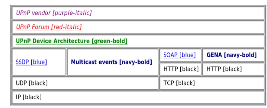
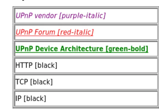
The UPnP Device Architecture (formerly known as the DCP Framework) contained herein defines the protocols for communication between controllers, or control points, and devices. For discovery, description, control, eventing, and presentation, the UPnP Device Architecture uses the following protocol stack (the indicated colors and type styles are used throughout this document to indicate where each protocol element is defined):
Figure
i-1: Protocol
stack
UPnP vendor [purple-italic] UPnP Forum [red-italic]
UPnP Device Architecture [green-bold]
SSDP [blue] Multicast events [navy-bold] SOAP [blue] GENA [navy-bold]
HTTP [black] HTTP [black]
UDP [black] TCP [black]
IP [black]
At the highest layer, messages logically contain only UPnP vendor-specific information about their devices. Moving down the stack, vendor content is supplemented by information defined by UPnP Forum working committees. Messages from the layers above are hosted in UPnP-specific protocols such as the Simple Service Discovery Protocol (SSDP), the General Event Notification Architecture (GENA) and the multicast event protocol defined in this document, and others that are referenced. SSDP is delivered via either multicast or unicast UDP. Multicast events are delivered via multicast UDP. GENA is delivered via HTTP. Ultimately, all messages above are delivered over IP. The remaining sections of this document describe the content and format for each of these protocol layers in detail. For reference, colors in [square brackets] above indicate which protocol defines specific message components throughout this document.
Two general classifications of devices are defined by the UPnP architecture: controlled devices (or simply “devices”), and control points. A controlled device functions in the role of a server, responding to requests from control points. Both control points and controlled devices can be implemented on a variety of platforms including personal computers and embedded systems. Multiple devices, control points, or both may be operational on the same network endpoint simultaneously.
Note: This document is oriented toward an IPv4 environment. Considerations for an IPv6 environment are expressed in Appendix A.
The foundation for UPnP networking is IP addressing. In an IPv4 environment, each device or control point must have a Dynamic Host Configuration Protocol (DHCP) client and search for a DHCP server when the device or control point is first connected to the network. If a DHCP server is available, i.e., the network is managed; the device or control point MUST use the IP address assigned to it. If no DHCP server is available, i.e., the network is unmanaged; the device or control point MUST use Auto IP to get an address. In brief, Auto IP defines how a device or control point intelligently chooses an IP address from a set of reserved addresses and is able to move easily between managed and unmanaged networks. If during the DHCP transaction, the device or control point obtains a domain name, e.g., through a DNS server or via DNS forwarding, the device or control point should use that name in subsequent network operations; otherwise, the device or control point should use its IP address.
Certain UPnP networks have more complex configurations such as multiple physical networks and/or multiple logical networks to accommodate multiple non-overlapping addressing schemes. Devices and control points may also have two or more network interfaces, and/or two or more IP addresses assigned to each interface. In such configurations, a single device or control point may be assigned multiple IP addresses from different logical networks in the same UPnP network, resulting in devices appearing to a control point multiple times in the network. Devices and control points that have multiple IP addresses on the same UPnP network are referred to as multi-homed. Throughout this document, the term "UPnP-enabled interface" is used to refer to an interface which is assigned an IP address belonging to the UPnP network. Additional behaviors specific to multi-homed devices and control points will be covered in applicable sections throughout the document. However, as a general principle, related interactions between control points and devices (e.g. action control request and response messages, event subscription and event messages) MUST occur using the same pair of outgoing and incoming UPnP-enabled interfaces.
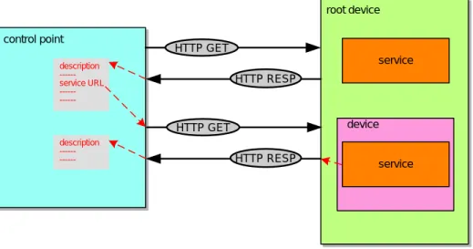
Given an IP address, Step 1 in UPnP networking is discovery. When a device is added to the network, the UPnP discovery protocol allows that device to advertise its services to control points on the network. Similarly, when a control point is added to the network, the UPnP discovery protocol allows that control point to search for devices of interest on the network. The fundamental exchange in both cases is a discovery message containing a few essential specifics about the device or one of its services, e.g., its type, identifier, and a pointer to more detailed information. The section on Discovery below explains how devices advertise, how control points search, and contains details about the format of discovery messages.
Step 2 in UPnP networking is description. After a control point has discovered a device, the control point still knows very little about the device. For the control point to learn more about the device and its capabilities, or to interact with the device, the
control point must retrieve the device's description from the URL provided by the device in the discovery message. Devices may contain other logical devices, as well as functional units, or services. The UPnP description for a device is expressed in XML and includes vendor-specific manufacturer information like the model name and number, the serial number, the manufacturer name, URLs to vendor-specific Web sites, etc. The description also includes a list of any embedded devices or services, as well as URLs for control, eventing, and presentation. For each service, the description includes a list of the commands, or actions, to which the service responds, and parameters, or arguments for each action; the description for a service also includes a list of variables; these variables model the state of the service at run time, and are described in terms of their data type, range, and event characteristics. The section on Description below explains how devices are described and how control points retrieve those descriptions.
Step 3 in UPnP networking is control. After a control point has retrieved a description of the device, the control point can send actions to a device's services. To do this, a control point sends a suitable control message to the control URL for the service (provided in the device description). Control messages are also expressed in XML using the Simple Object Access Protocol (SOAP). Like function calls, in response to the control message, the service returns any action-specific values. The effects of the action, if any, are modeled by changes in the variables that describe the run-time state of the service. The section on Control below explains the description of actions, state variables, and the format of control messages.
Step 4 in UPnP networking is eventing. A UPnP description for a service includes a list of actions the service responds to and a list of variables that model the state of the service at run time. The service publishes updates when these variables change, and a control point may subscribe to receive this information. The service publishes updates by sending event messages. Event messages contain the names of one or more state variables and the current value of those variables. These messages are also expressed in XML. A special initial event message is sent when a control point first subscribes; this event message contains the names and values for all evented variables and allows the subscriber to initialize its model of the state of the service. To support scenarios with multiple control points, eventing is designed to keep all control points equally informed about the effects of any action. Therefore, all subscribers are sent all event messages, subscribers receive event messages for all evented variables that have changed, and event messages are sent no matter why the state variable changed (either in response to a requested action or because the state the service is modeling changed). Multicast eventing is a variant of Step 4 in UPnP networking. Through multicast eventing, control points can listen to state changes in services without subscription. This form of eventing is useful first when events which are not relevant to specific UPnP interactions should be delivered to control points to inform users, and second when multiple controlled devices want to inform multiple other control points. Multicast eventing is inherently unreliable since it is based on UDP. To increase the probability of successful transmission, the option to retransmit multicast event notifications is outlined. UPnP Working committees should define whether specific events are multicast events. The section on Eventing below explains unicast event subscription and the format of both unicast and multicast event messages.
Step 5 in UPnP networking is presentation. If a device has a URL for presentation, then the control point can retrieve a page from this URL, load the page into a browser, and depending on the capabilities of the page, allow a user to control the device
and/or view device status. The degree to which each of these can be accomplished depends on the specific capabilities of the presentation page and device. The section on Presentation below explains the protocol for retrieving a presentation page.
i.4
Audience
The audience for this document includes UPnP device and control point vendors, members of UPnP Forum working committees, and anyone else who has a need to understanding the technical details of UPnP protocols.
This document assumes the reader is familiar with the HTTP, TCP, UDP, IP family of protocols; this document makes no attempt to explain them. This document also assumes most readers will be new to XML, and while it is not an XML tutorial, XML-related issues are addressed in detail given the centrality of XML to the UPnP Device Architecture. This document makes no assumptions about the reader's understanding of various programming or scripting languages.
i.5
Conformance terminology
In this document, features are described as REQUIRED, RECOMMENDED, OPTIONAL or DEPRECATED as follows: REQUIRED (or MUST or MANDATORY).
These basic features MUST be implemented to comply with UPnP Device Architecture. The phrases “MUST NOT”, and “PROHIBITED” indicate behavior that is prohibited, i.e. that if performed means the implementation is not in compliance. RECOMMENDED (or SHOULD).
These features add functionality supported by UPnP Device Architecture and SHOULD be implemented. RECOMMENDED features take advantage of the capabilities UPnP Device Architecture, usually without imposing major cost increases. Notice that for compliance testing, if a RECOMMENDED feature is implemented, it MUST meet the specified requirements to be in compliance with these guidelines. Some RECOMMENDED features could become requirements in the future. The phrase “SHOULD NOT” indicates behavior that is permitted but NOT RECOMMENDED.
OPTIONAL (or MAY).
These features are neither REQUIRED nor RECOMMENDED by UPnP Device Architecture, but if the feature is implemented, it MUST meet the specified requirements to be in compliance with these guidelines. These features are not likely to become requirements in the future.
DEPRECATED.
Although these features are still described in this specification, they should not be implemented except for backward compatibility. The occurrence of a deprecated feature during operation of an implementation compliant with the current specification has no effect on the implementation’s operation and does not produce any error conditions. Backward compatibility may require that a feature is implemented and functions as specified but it MUST never be used by implementations compliant with this specification.
i.6
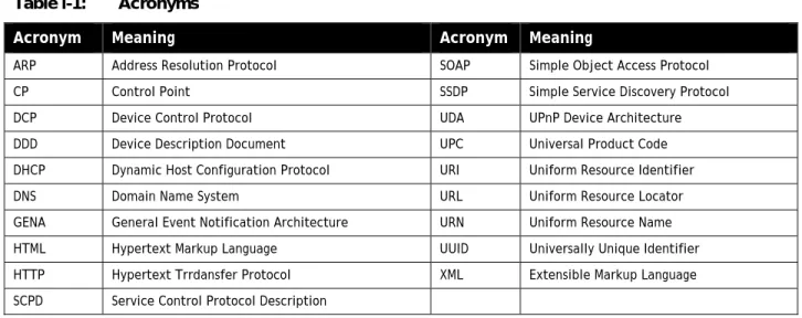
Acronyms
Table
i-1: Acronyms
Acronym
Meaning
Acronym Meaning
ARP Address Resolution Protocol SOAP Simple Object Access Protocol CP Control Point SSDP Simple Service Discovery Protocol DCP Device Control Protocol UDA UPnP Device Architecture DDD Device Description Document UPC Universal Product Code DHCP Dynamic Host Configuration Protocol URI Uniform Resource Identifier DNS Domain Name System URL Uniform Resource Locator GENA General Event Notification Architecture URN Uniform Resource Name HTML Hypertext Markup Language UUID Universally Unique Identifier HTTP Hypertext Trrdansfer Protocol XML Extensible Markup Language SCPD Service Control Protocol Description
i.7
Glossary
action
Command exposed by a service. Takes one or more input or output arguments. May have a return value. For more information, see section 2, “Description” and section 3, “Control”.
argument
Parameter for action exposed by a service. May be in or out. For more information, see section 2, “Description” and section 3, “Control”.
control point
Retrieves device and service descriptions, sends actions to services, polls for service state variables, and receives events from services.
device
Logical device. A container. May embed other logical devices. Embeds one or more services. Advertises its presence on network(s). For more information, see section 1, “Discovery” and section 2, “Description”.
device description
Formal definition of a logical device, expressed in the UPnP Template Language. Written in XML syntax. Specified by a UPnP vendor by filling in the placeholders in a UPnP Device Template, including, e.g., manufacturer name, model name, model number, serial number, and URLs for control, eventing, and presentation. For more information, see section 2,
“Description”. device type
Standard device types are denoted by urn:schemas-upnp-org:device: followed by a unique name assigned by a UPnP Forum working committee. One-to-one relationship with UPnP Device Templates. UPnP vendors may specify additional device types; these are denoted by urn:name:device: followed by a unique name assigned by the vendor, where
domain-name is a Vendor Domain Name. For more information, see section 2, “Description” . event
Notification of one or more changes in state variables exposed by a service. For more information, see section 4, “Eventing”. GENA
General Event Notification Architecture. The event subscription and notification protocol defined in section 4, “Eventing”. publisher
Source of event messages. Typically a device's service. For more information, see section 4, “Eventing”. root device
A logical device that is not embedded in any other logical device. For more information, see section 2, “Description”. service
Logical functional unit. Smallest units of control. Exposes actions and models the state of a physical device with state variables. For more information, see section 3, “Control”.
service description
Formal definition of a logical service, expressed in the UPnP Template language. Written in XML syntax. Specified by a UPnP vendor by filling in any placeholders in a UPnP Service Template. (Was SCPD.) For more information, see section 2,
“Description”. service type
Standard service types are denoted by urn:schemas-upnp-org:service: followed by a unique name assigned by a UPnP forum working committee, colon, and an integer version number. One-to-one relationship with UPnP Service Templates. UPnP vendors may specify additional services; these are denoted by urn:domain-name:service: followed by a unique name assigned by the vendor, colon, and a version number, where domain-name is a Vendor Domain Name. For more information, see section 2, “Description”.
SOAP
Simple Object Access Protocol. A remote-procedure call mechanism based on XML that sends commands and receives values over HTTP. For more information, see section 3, “Control”.
SSDP
Simple Service Discovery Protocol. A multicast discovery and search mechanism that uses a multicast variant of HTTP over UDP. Defined in section 1, “Discovery”.
state variable
Single facet of a model of a physical service. Exposed by a service. Has a name, data type, optional default value, optional constraints values, and may trigger events when its value changes. For more information, see section 2, “Description” and section 3, “Control”.
subscriber
Recipient of event messages. Typically a control point. For more information, see section 4, “Eventing”. UPnP Device Template
Template listing device type, required embedded devices (if any), and required services. Written in XML syntax and derived from the UPnP Device Schema. Defined by a UPnP Forum working committee. One-to-one relationship with standard device types. For more information, see section 2, “Description”.
UPnP Service Template
Template listing action names, parameters for those actions, state variables, and properties of those state variables. Written in XML syntax and derived from the UPnP Service Schema. Defined by a UPnP Forum working committee. One-to-one relationship with standard service types. For more information, see section 2, “Description”.
UPnP Device Schema
Defines the elements and attributes used in UPnP Device and Service Templates. Written in XML syntax and derived from XML Schema (Part 1: Structures, Part 2: Datatypes). Defined by the UPnP Device Architecture herein. For more information, see section 2, “Description”.
Vendor Domain Name
A domain name that is supplied by a vendor. It is owned by the vendor, and MUST be registered with an ICANN accredited Registrar, such that it is unique. The vendor MUST keep the domain name registration up to date. A Vendor Domain Name length SHOULD be chosen to be compatible with the use of the domain name in the UDA.
i.8
References and resources
RFC 2710
Multicast Listener Discovery for IPv6. Available at: http://www.ietf.org/rfc/rfc2710.txt. RFC 2616
HTTP: Hypertext Transfer Protocol 1.1. Available at: http://www.ietf.org/rfc/rfc2616.txt. RFC 2279
UTF-8, a transformation format of ISO 10646 (character encoding). Available at: http://www.ietf.org/rfc/rfc2279.txt. XML
Extensible Markup Language. W3C recommendation. Available at: http://www.w3.org/XML/. Each section in this document contains additional information about resources for specific topics.
0 Addressing
[Normative]
Addressing is Step 0 of UPnP™ networking. Through addressing, devices and control points get a network address. Addressing enables discovery (Step 1) where control points find interesting device(s), description (Step 2) where control points learn about device capabilities, control (Step 3) where a control point sends commands to device(s), eventing (Step 4) where control points listen to state changes in device(s), and presentation (Step 5) where control points display a user interface for device(s).
The foundation for UPnP networking is IP addressing. A UPnP device or control point MAY support IP version 4-only, or both IP version 4 and IP version 6. This section, and the examples given throughout sections 1 through 5 of this document, assumes an IPv4 implementation. Annex A of this document describes IPv6 operation. Each UPnP device or control point which does not itself implement a DHCP server MUST have a Dynamic Host Configuration Protocol (DHCP) client and search for a DHCP server when the device or control point is first connected to the network (if the device or control point itself implements a DHCP server, it MAY allocate itself an address from the pool that it controls). If a DHCP server is available, i.e., the network is managed; the device or control point MUST use the IP address assigned to it. If no DHCP server is available, i.e., the network is unmanaged; the device or control point MUST use automatic IP addressing (Auto-IP) to obtain an address.
Auto-IP (defined in RFC 3927) defines how a device or control point: (a) determines if DHCP is unavailable, and (b) intelligently chooses an IP address from a set of link-local IP addresses. This method of address assignment enables a device or control point to easily move between managed and unmanaged networks.
This section provides an overview of the basic operation of Auto-IP. The operations described in this section are detailed and clarified in the reference documents listed below. Where conflicts between this document and the reference documents exist, the reference document always takes precedence.
0.1 Determining whether to use Auto-IP
A device or control point that supports Auto-IP and is configured for dynamic address assignment begins by requesting an IP address via DHCP by sending out a DHCPDISCOVER message. The amount of time this DHCP Client listens for DHCPOFFERs is implementation dependent. If a DHCPOFFER is received during this time, the device or control point MUST continue the process of dynamic address assignment. If no valid DHCPOFFERs are received, the device or control point MUST then auto-configure an IP address using Auto-IP.
0.2 Choosing an address
To auto-configure an IP address using Auto-IP, the device or control point uses an implementation dependent algorithm for choosing an address in the 169.254/16 range. The first and last 256 addresses in this range are reserved and MUST NOT be used. The selected address MUST then be tested to determine if the address is already in use. If the address is in use by another device or control point, another address MUST be chosen and tested, up to an implementation dependent number of retries. The
address selection MUST be randomized to avoid collision when multiple devices or control points are attempting to allocate addresses. The device or control point chooses an address using a pseudo-random algorithm (distributed over the entire address range from 169.254.1.0 to 169.254.254.255) to minimize the likelihood that devices or control points that join the network at the same time will choose the same address and subsequently choose alternative addresses in the same sequence when collisions are detected. This pseudo-random algorithm SHOULD be seeded using the device’s or control point’s Ethernet hardware MAC address.
0.3 Testing the address
To test the chosen address, the device or control point MUST use an Address Resolution Protocol (ARP) probe. An ARP probe is an ARP request with the device or control point hardware address used as the sender's hardware address and the sender's IP address set to 0s. The device or control point MUST then listen for responses to the ARP probe, or other ARP probes for the same IP address. If either of these ARP packets is seen, the device or control point MUST consider the address in use and try a different address. The ARP probe MAY be repeated for greater certainty that the address is not already in use; it is RECOMMENDED that the probe be sent four times at two-second intervals.
After successfully configuring a link-local address, the device or control point MUST send two gratuitous ARPs, spaced two seconds apart, this time filling in the sender IP address. The purpose of these gratuitous ARPs is to make sure that other hosts on the net do not have stale ARP cache entries left over from some other host that may previously have been using the same address.
Devices and control points that are equipped with persistent storage MAY record the IP address they have selected and on the next boot use that address as their first candidate when probing, in order to increase the stability of addresses and reduce the need to resolve address conflicts.
Address collision detection is not limited to the address testing phase, when the device or control point is sending ARP probes and listening for replies. Address collision detection is an ongoing process that is in effect for as long as the device or control point is using a link-local address. At any time, if a device or control point receives an ARP packet with its own IP address given as the sender IP address, but a sender hardware address that does not match its own hardware address, then the device or control point MUST treat this as an address collision and MUST respond as described in either (a) or (b) below:
(a) Immediately configure a new link-local IP address as described above; or,
(b) If the device or control point currently has active TCP connections or other reasons to prefer to keep the same IP address, and has not seen any other conflicting ARP packets recently (e.g., within the last ten seconds) then it MAY elect to attempt to defend its address once, by recording the time that the conflicting ARP packet was received, and then broadcasting one single gratuitous ARP, giving its own IP and hardware addresses as the source addresses of the ARP. However, if another conflicting ARP packet is received within a short time after that (e.g., within ten seconds) then the device or control point MUST immediately configure a new Auto-IP address as described above.
The device or control point MUST respond to conflicting ARP packets as described in either (a) or (b) above; it MUST NOT ignore conflicting ARP packets. If a new address is selected, the device or control point MUST cancel previous advertisements and re-advertise with the new address.
After successfully configuring an Auto-IP address, all subsequent ARP packets (replies as well as requests) containing an Auto-IP source address MUST be sent using link-level broadcast instead of link-level unicast, in order to facilitate timely detection of duplicate addresses.
0.4 Forwarding rules
IP packets whose source or destination addresses are in the 169.254/16 range MUST NOT be sent to any router for forwarding. Instead, the senders MUST ARP for the destination address and then send the packets directly to the destination on the same link. IP datagrams with a multicast destination address and an Auto-IP source address MUST NOT be forwarded off the local link. Devices and control points MAY assume that all 169.254/16 destination addresses are on-link and directly reachable. The 169.254/16 address range MUST NOT be subnetted.
0.5 Periodic checking for dynamic address availability
A device or control point that has auto-configured an IP address MUST periodically check for the existence of a DHCP server. This is accomplished by sending DHCPDISCOVER messages. How often this check is made is implementation dependent, but checking every 5 minutes would maintain a balance between network bandwidth required and connectivity maintenance. If a DHCPOFFER is received, the device or control point MUST proceed with dynamic address allocation. Once a DHCP assigned address is in place, the device or control point MAY release the auto-configured address, but MAY also choose to maintain this address for a period of time (or indefinitely) to maintain connectivity.
To switch over from one IP address to a new one, the device SHOULD, if possible, cancel any outstanding advertisements made on the previous address and MUST issue new advertisements on the new address. The section on Discovery explains
advertisements and their cancellations. In addition, any event subscriptions are deleted by the device (see section on Eventing). For a multi-homed device with multiple IP addresses, to switch one of the IP addresses to a new one, the device SHOULD cancel any outstanding advertisements made on the previous IP address, and MUST issue new advertisements on the new IP addresses. Furthermore, it MUST also issue appropriate update advertisements on all unaffected IP addresses. The section on Discovery explains advertisements, their cancellations and updates. The section on Eventing explains the effect on event subscriptions.
0.6 Device naming and DNS interaction
Once a device has a valid IP address for the network, it can be located and referenced on that network through that address. There may be situations where the end user needs to locate and identify a device. In these situations, a friendly name for the device is much easier for a human to use than an IP address. If a device chooses to provide a host name to a DHCP server and register with a DNS server, the device SHOULD either ensure the requested host name is unique or provide a means for the user
to change the requested host name. Most often, devices do not provide a host name, but provide URLs using literal (numeric) IP addresses.
Moreover, names are much more static than IP addresses. Clients referring a device by name don't require any modification when the IP address of a device changes. Mapping of the device's DNS name to its IP address could be entered into the DNS database manually or dynamically according to RFC 2136. While devices supporting dynamic DNS updates can register their DNS records directly in the DNS, it is also possible to configure a DHCP server to register DNS records on behalf of these DHCP clients.
0.7 Name to IP address resolution
A device that needs to contact another device identified by a DNS name needs to discover its IP address. The device submits a DNS query according to RFC1034 and 1035 to the pre-configured DNS server(s) and receives a response from a DNS server containing the IP address of the target device. A device can be statically pre-configured with the list of DNS servers.
Alternatively a device could be configured with the list of DNS server through DHCP, or after the address assignment through a DHCPINFORM message.
0.8 References
RFC1034
Domain Names - Concepts and Facilities. Available at: http://www.ietf.org/rfc/rfc1034.txt. RFC1035
Domain Names - Implementation and Specification. Available at: http://www.ietf.org/rfc/rfc1035.txt. RFC 2131
Dynamic Host Configuration Protocol. Available at: http://www.ietf.org/rfc/rfc2131.txt. RFC 2136
Dynamic Updates in the Domain Name System. Available at: http://www.ietf.org/rfc/rfc2136.txt. RFC 3927
1 Discovery
[Normative]
Discovery is Step 1 in UPnP™ networking. Discovery comes after addressing (Step 0) where devices get a network address. Through discovery, control points find interesting device(s). Discovery enables description (Step 2) where control points learn about device capabilities, control (Step 3) where a control point sends commands to device(s), eventing (Step 4) where control points listen to state changes in device(s), and presentation (Step 5) where control points display a user interface for device(s).
Discovery is the first step in UPnP networking. When a device is added to the network, the UPnP discovery protocol allows that device to advertise its services to control points on the network. Similarly, when a control point is added to the network, the UPnP discovery protocol allows that control point to search for devices of interest on the network. The fundamental exchange in both cases is a discovery message containing a few, essential specifics about the device or one of its services, e.g., its type, universally unique identifier, a pointer to more detailed information and optionally parameters that identify the current state of the device.
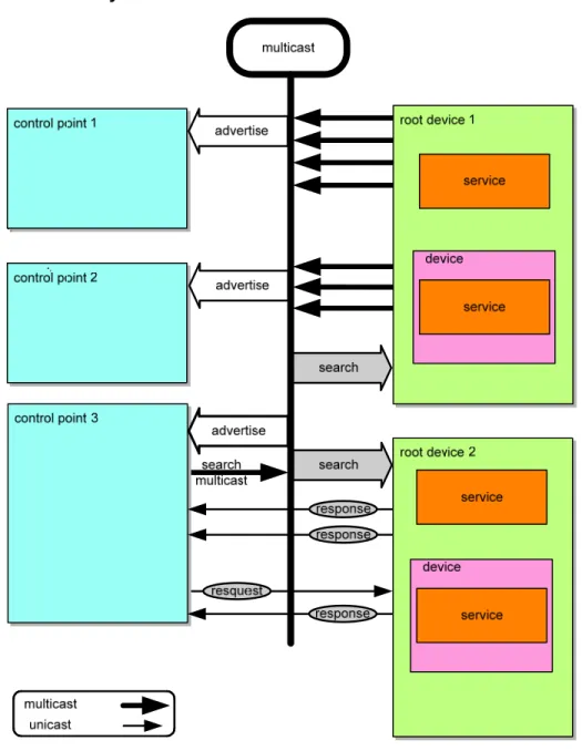
Figure
1-1: Discovery
architecture
When a device knows it is newly added to the network, it MUST multicast a number of discovery messages advertising itself, its embedded devices, and its services (initial announce). Any interested control point can listen to the standard multicast address for notifications that new capabilities are available. A multi-homed device MUST multicast the discovery messages on all enabled interfaces. A multi-homed control point MAY listen to the standard multicast address on one, some or all of its UPnP-enabled interfaces.
When a new control point is added to the network, it MAY multicast a discovery message searching for interesting devices, services, or both. All devices MUST listen to the standard multicast address for these messages and MUST respond if any of their root devices, embedded devices or services matches the search criteria in the discovery message. In addition, a control point
SEARCHPORT.UPNP.ORG header field (which supersedes port 1900 for this use), searching for a UPnP device or service at that specific IP address. This action presumes the control point already knows the device at this IP address is a UPnP 1.1 device (which listens on the appropriate port). The control point can use unicast search for a number of applications. A unicast search can quickly confirm a specific device and provide the corresponding discovery information (e.g. UUID, URL) of this device. All devices MUST listen to incoming unicast search messages on port 1900 or, if provided, the port number specified in the SEARCHPORT.UPNP.ORG header field and MUST respond if any of their root devices, embedded devices or services matches the search criteria in the discovery message.
A multi-homed control point MAY multicast discovery messages on one, some or all of its UPnP-enabled interfaces. Multi-homed devices MUST listen to the standard multicast address on all UPnP-enabled interfaces for multicast discovery messages. Multi-homed devices MUST also listen to incoming unicast search messages on port 1900 or, if provided, the port number specified in the SEARCHPORT.UPNP.ORG header field. The devices MUST respond if any of their root devices, embedded devices or services matches the search criteria in the discovery message.
To reiterate, a control point MAY learn of a device of interest because that device sent discovery messages advertising itself or because the device responded to a discovery message searching for devices. In either case, if a control point is interested in a device and wants to learn more about it, the control point uses the information in the discovery message to send a description query message. The section on Description explains description messages in detail.
When a device is removed from the network, it SHOULD, if possible, multicast a number of discovery messages revoking its earlier announcements, effectively declaring that its root devices, embedded devices and services will no longer be available. When the IP address of a device is changed, it SHOULD revoke any earlier announcements and it MUST advertise using the new IP address.
When a multi-homed device becomes unavailable to the network on any of its UPnP-enabled interfaces, it SHOULD, if possible, multicast a number of discovery messages revoking its earlier announcements on the affected UPnP-enabled interfaces, effectively declaring that its root devices, embedded devices and services will no longer be available on those interfaces. If it remains available to the network on any of its other UPnP-enabled interfaces, it MUST NOT multicast such discovery messages on the unaffected UPnP-enabled interfaces.
When a multi-homed device becomes available to the network on a new UPnP-enabled interface (in addition to any existing UPnP-enabled interfaces), it MUST increase its BOOTID.UPNP.ORG field value (see section 1.2 “Advertisement”), and multicast a number of update messages on the existing UPnP-enabled interfaces to announce the new BOOTID.UPNP.ORG field value. After all the update messages have been sent, it MUST multicast a number of discovery messages on all (existing and new) UPnP-enabled interfaces with the new BOOTID.UPNP.ORG field value.
Similarly, when one of the IP addresses of a multi-homed device is changed, it SHOULD revoke any earlier announcements on the previous IP address. It MUST increase its BOOTID.UPNP.ORG field value (see section 1.2 “Advertisement”), and multicast a
number of update messages on the existing UPnP-enabled interfaces to announce the new BOOTID.UPNP.ORG field value. After all the update messages have been sent, it MUST multicast a number of discovery messages on all (existing and new) UPnP-enabled interfaces with the new BOOTID.UPNP.ORG field value.
Finally, if a multi-homed device loses connectivity on one of its UPnP-enabled interfaces and then regains connectivity, it MUST increase its BOOTID.UPNP.ORG field value (see section “1.2Advertisement”), and multicast a number of update messages on the unaffected UPnP-enabled interfaces to announce the new BOOTID.UPNP.ORG field value. After all the update messages have been sent, it MUST multicast a number of discovery messages on all (affected and unaffected) UPnP-enabled interfaces with the new BOOTID.UPNP.ORG field value.
To limit network congestion, the time-to-live (TTL) of each IP packet for each multicast message SHOULD default to 2 and SHOULD be configurable. When the TTL is greater than 1, it is possible for multicast messages to traverse multiple routers; therefore control points and devices using non-AutoIP addresses MUST send an IGMP Join message so that routers will forward multicast messages to them (this is not necessary when using an Auto-IP address, since packets with Auto-IP addresses will not be forwarded by routers).
Versioning: Discovery plays an important role in the interoperability of devices and control points using different versions of
UPnP networking. The UPnP Device Architecture (defined herein) is versioned with both a major and a minor version, usually written as major.minor, where both major and minor are integers (for example, version 2.10 [two dot ten] is newer than version 2.2 [two dot two]). Advances in minor versions MUST be a compatible superset of earlier minor versions of the same major version. Advances in major version are not required to be supersets of earlier versions and are not guaranteed to be backward compatible. Version information is communicated in discovery and description messages. Discovery messages include the version of UPnP networking that the devices and control points support (in the SERVER and USER-AGENT header fields); the version of device and service types supported is also included in relevant discovery messages. Additionally, description documents also include the same information. SERVER and USER-AGENT header fields are also used in control and eventing to communicate which version of UPnP networking the devices and control points support. This section explains the format of version information in discovery messages and specific requirements on discovery messages to maintain compatibility with advances in minor versions. The remainder of this section explains the UPnP discovery protocol known as SSDP (Simple Service Discovery Protocol) in detail, enumerating how devices advertise and revoke their advertisements as well as how control points search and devices respond.
1.1 SSDP message format
SSDP uses part of the header field format of HTTP 1.1 as defined in RFC 2616. However, it is NOT based on full HTTP 1.1 as it uses UDP instead of TCP, and it has its own processing rules. This section defines the generic format of a SSDP message.
All SSDP messages MUST be formatted according to RFC 2616 section 4.1 “generic message”. SSDP messages MUST have a start-line and a list of message header fields. SSDP messages SHOULD NOT have a message body. If a SSDP message is received with a message body, the message body MAY be ignored.
1.1.1 SSDP Start-line
Each SSDP message MUST have exactly one start-line. See section 1.2, “Advertisement” and section 1.3, “Search” below for the definition of all possible SSDP messages. The start-line MUST be formatted either as defined in RFC 2616 section 5.1 or section 6.1. Furthermore, the start-line MUST be one of the following three:
NOTIFY * HTTP/1.1\r\n M-SEARCH * HTTP/1.1\r\n HTTP/1.1 200 OK\r\n
As a clarification, while the start-line MUST include “HTTP/1.1”, this does not signal that SSDP is fully based on HTTP 1.1; this start-line element is included for backward compatibility reasons only.
1.1.2 SSDP message header fields
The message header fields in a SSDP message MUST be formatted according to RFC 2616 section 4.2. This specifies that each message header field consist of a case-insensitive field name followed by a colon (":"), followed by the case-sensitive field value. SSDP restricts allowed field values.
Example SSDP header:
HOST: 239.255.255.250:1900
1.1.3 SSDP header field extensions
UPnP working committees and UPnP vendors are allowed to extend SSDP messages with additional SSDP header fields. Additional message header fields can also be defined by the UPnP Forum Technical committee (e.g. section 1.2, “Advertisement” defines BOOTID.UPNP.ORG, CONFIGID.UPNP.ORG, NEXTBOOTID.UPNP.ORG, and SEARCHPORT.UPNP.ORG header fields). To prevent name-clashes of header field definitions (two parties accidentally define the same header field name with different semantics), vendor-defined header field names MUST have the following format:
field-name = token “.” domain-name
where the domain-name MUST be Vendor Domain Name, and in addition MUST satisfy the token format as defined in RFC 2616, section 2.2.
Example vendor-defined SSDP header fields:
myheader.philips.com: “some value” myheader.sony.com: “other value”
1.1.4 UUID format and RECOMMENDED generation algorithms
UPnP 1.1 devices MUST format UUIDs according to the format specified below. However, UPnP 1.1 control points MUST also be able to accept UUIDs that have not been formatted according to the rules specified below, as formatting rules are not specified in UPnP 1.0 other than the requirement that a UUID is a string.
UUIDs are 128 bit numbers that MUST be formatted as specified by the following grammar (taken from [1]): UUID = 4 * <hexOctet> “-” 2 * <hexOctet> “-” 2 * <hexOctet> “-” 2 * <hexOctet> “-” 6 * <hexOctet hexOctet = <hexDigit> <hexDigit>
hexDigit = “0”|“1”|“2”|“3”|“4”|“5”|“6”|“7”|“8”|“9”|“a”|“b”|“c”|“d”|“e”|“f”|“A”|“B”|“C”|“D”|“E”|“F” The following is an example of the string representation of a UUID:
“2fac1234-31f8-11b4-a222-08002b34c003”
UUIDs MAY be generated using any suitable generation algorithm2 that satisfies the following requirements: 1. It is very unlikely to duplicate a UUID generated from some other resource.
2. It maps down to a 128-bit number. 3. UUIDs MUST remain fixed over time.
The following UUID generation algorithm is RECOMMENDED:
Time & MAC-based algorithm as specified in [1], where the UUID is generated once and stored in non-volatile memory if available.
1.1.5 SSDP processing rules
When an SSDP message is received that is not formatted according to section 1.1, “SSDP message format” (the sections above), receivers SHOULD silently discard the message. Receivers MAY try to parse such SSDP messages to try to interoperate.
When parsing SSDP header fields, receivers MUST parse all REQUIRED SSDP-defined header fields (see section 1.2,
“Advertisement” and section 1.3, “Search” below) and MAY skip all other header fields. Receivers MUST be able to skip header fields they do not understand.
1.2 Advertisement
When a device is added to the network, the device advertises its services to control points. It does this by multicasting discovery messages to a standard address and port (239.255.255.250:1900). Control points listen to this port to detect when new
capabilities are available on the network. To advertise the full extent of its capabilities, a device MUST multicast a number of discovery messages corresponding to each of its root devices, embedded devices and services. Each message contains information specific to the embedded device (or service) as well as information about its enclosing device. Messages MUST include duration
until the advertisements expire; if the device remains available, the advertisements MUST be re-sent (with new duration). If the device becomes unavailable, the device SHOULD explicitly cancel its advertisements, but if the device is unable to do this, the advertisements will expire on their own. If a multi-homed device becomes unavailable on some, but not all, of its UPnP-enabled interfaces, the device SHOULD explicitly cancel its advertisements on the affected UPnP-enabled interfaces (but NOT on the unaffected UPnP-enabled interfaces), but if the device is unable to do this, the advertisements on those interfaces or IP addresses will expire on their own. In addition, messages include the following header fields defined in this document: BOOTID.UPNP.ORG, NEXTBOOTID.UPNP.ORG, CONFIGID.UPNP.ORG, SEARCHPORT.UPNP.ORG. The field value of the
BOOTID.UPNP.ORG header field MUST be increased each time a device (re)joins the network and sends an initial announce (a “reboot” in UPnP terms), or adds a UPnP-enabled interface. Unless the device explicitly announces a change in the
BOOTID.UPNP.ORG field value using an SSDP message, as long as the device remains continuously available in the network, the same BOOTID.UPNP.ORG field value MUST be used in all repeat announcements, search responses, update messages and eventually bye-bye messages. Control points can parse this header field to detect whether the device has potentially lost its state (event subscriptions will have been lost, DCP specific state may have been changed) due to a “reboot”. Since a device cannot change IP addresses without changing the BOOTID.UPNP.ORG field value, the BOOTID.UPNP.ORG field value can also be used to distinguish multi-homed devices (in this case, a control point will see SSDP messages from different IP addresses with the same UUID, BOOTID.UPNP.ORG field value) from devices that changed IP addresses (in this case, the BOOTID.UPNP.ORG field value will be different). The field value of the NEXTBOOTID.UPNP.ORG header field indicates the field value of the
BOOTID.UPNP.ORG header field that a multi-homed device intends to use in future announcements after adding a new UPnP-enabled interface. The field value of the CONFIGID.UPNP.ORG header field identifies the current set of device and service descriptions; control points can parse this header field to detect whether they need to send new description query messages. The field value of the SEARCHPORT.UPNP.ORG header field identifies the port at which the device listens to unicast M-SEARCH messages; control points can parse this header field to know to which port unicast M-SEARCH messages MUST be sent. These header fields are explained in detail below.
1.2.1 Advertisement protocols and standards
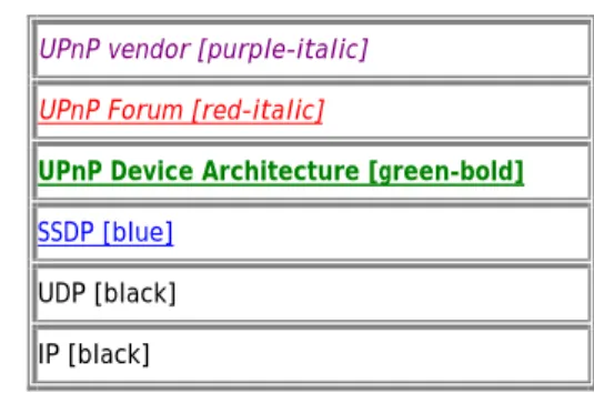
To send (and receive) advertisements, devices (and control points) use the following subset of the overall UPnP protocol stack. (The overall UPnP protocol stack is listed at the beginning of this document.)
Figure
1-2:
Advertisement protocol stack
UPnP vendor [purple-italic] UPnP Forum [red-italic]
UPnP Device Architecture [green-bold]
SSDP [blue]
UDP [black] IP [black]
At the highest layer, discovery messages contain vendor-specific information, e.g., URL for the device description and device identifier. Moving down the stack, vendor content is supplemented by information from a UPnP Forum working committee, e.g., device type. Messages from the layers above are hosted in UPnP-specific protocols, defined in this document. In turn, the SSDP messages are delivered via UDP over IP. For reference, colors in [square brackets] above indicate which protocol defines specific header fields and field values in discovery messages listed below.
1.2.2 Device available - NOTIFY with ssdp:alive
When a device is added to the network, it MUST multicast discovery messages to advertise its root device, any embedded devices, and any services. Each discovery message MUST contain four major components:
1. A notification type (e.g., device type), sent in an NT (Notification Type) header field.
2. A composite identifier for the advertisement, sent in a USN (Unique Service Name) header field.
3. A URL for more information about the device (or enclosing device in the case of a service), sent in a LOCATION header field.
4. A duration for which the advertisement is valid, sent in a CACHE-CONTROL header field.
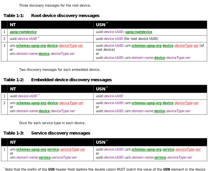
• Three discovery messages for the root device.
Table
1-1:
Root device discovery messages
NT
USN
*1 upnp:rootdevice uuid:device-UUID::upnp:rootdevice
2 uuid:device-UUID** uuid:device-UUID (for root device UUID) 3 urn:schemas-upnp-org:device:deviceType:ver
or
urn:domain-name:device:deviceType:ver
uuid:device-UUID::urn:schemas-upnp-org:device:deviceType:ver (of root device)
or
uuid:device-UUID::urn:domain-name:device:deviceType:ver
• Two discovery messages for each embedded device.
Table
1-2:
Embedded device discovery messages
NT
USN
*1 uuid:device-UUID** uuid:device-UUID 2 urn:schemas-upnp-org:device:deviceType:ver
or
urn:domain-name:device:deviceType:ver
uuid:device-UUID::urn:schemas-upnp-org:device:deviceType:ver
or
uuid:device-UUID::urn:domain-name:device:deviceType:ver
• Once for each service type in each device.
Table
1-3:
Service discovery messages
NT
USN
*1 urn:schemas-upnp-org:service:serviceType:ver
or
urn:domain-name:service:serviceType:ver
uuid:device-UUID::urn:schemas-upnp-org:service:serviceType:ver
or
uuid:device-UUID::urn:domain-name:service:serviceType:ver
* Note that the prefix of the USN header field (before the double colon) MUST match the value of the UDN element in the device description. (Section 2, “Description” explains the UDN element.)
** Note that the field value of this NT header field MUST match the value of the UDN element in the device description. If a root device has d embedded devices and s embedded services but only k distinct service types, this works out to 3+2d+k requests. If a particular device or embedded device contains multiple instances of a particular service type, it is only necessary to advertise the service type once (rather than once for each instance). Note that if two embedded devices contain a service of the same service type, these services MUST still be separately announced. This advertises the full extent of the device's capabilities to interested control points. These messages MUST be sent out as a series with roughly comparable expiration times; order is unimportant, but refreshing or canceling individual messages is PROHIBITED.
Updated UPnP device and service types are REQUIRED to be fully backward compatible with previous versions of the same type. Devices MUST advertise the highest supported version of each supported type. For example, if a device supports version 2 of the “Audio” service, it would advertise only version 2, even though it also supports version 1. It MUST NOT advertise additional supported versions. Control points that support a given version of a device or service are able to also interact with higher
versions because of this backward compatibility requirement, but only using the functionality that was defined in the lower version. For example, if a control point supports only version “1” of the “Audio” service, and a device advertises that it supports version “2” of the “Audio” service, the control point MUST recognize the device and be able to use it.
Choosing an appropriate duration for advertisements is a balance between minimizing network traffic and maximizing freshness of device status. Relatively short durations close to the minimum of 1800 seconds will ensure that control points have current device status at the expense of additional network traffic; longer durations, say on the order of a day, compromise freshness of device status but can significantly reduce network traffic. Generally, device vendors should choose a value that corresponds to expected device usage: short durations for devices that are expected to be part of the network for short periods of time, and significantly longer durations for devices expected to be long-term members of the network. Devices that frequently connect to and leave the network (such as mobile wireless devices) SHOULD use a shorter duration so that control points have a more accurate view of their availability. Advertisements in a set (both initial and subsequent) SHOULD have comparable durations. Advertisements in the initial set SHOULD be sent as quickly as possible. Subsequent refreshments of the advertisements MAY be spread over time rather than being sent as a group.
Spreading refreshments of advertisements over time rather than being sent as a group improves reliability in case there are network glitches: without increasing the total network load it increases the frequency of sending announcements from devices to control points. The two figures below show the announcement behavior without spreading and with spreading the messages over the entire interval. The figures show a timeline from the moment a device joins the network, sends its initial announcements (represented by vertical lines), and subsequently periodically sends repeat announcements. In the second figure, these repeat announcements are spread over the entire period rather than sent as a bunch.
Figure
1-3:
Initial and repeat announcements, no announcement spreading
Figure
1-4:
Initial and repeat announcements, message spreading of repeat announcements
Devices SHOULD wait a random interval (e.g. between 0 and 100milliseconds) before sending an initial set of advertisements in order to reduce the likelihood of network storms; this random interval SHOULD also be applied on occasions where the device obtains a new IP address or a new UPnP-enabled interface is installed.
Due to the unreliable nature of UDP, devices SHOULD send the entire set of discovery messages more than once with some delay between sets e.g. a few hundred milliseconds. To avoid network congestion discovery messages SHOULD NOT be sent more than
the CACHE-CONTROL header field; it is RECOMMENDED that such refreshing of advertisements be done at a randomly-distributed interval of less than one-half of the advertisement expiration time, so as to provide the opportunity for recovery from lost advertisements before the advertisement expires, and to distribute over time the advertisement refreshment of multiple devices on the network in order to avoid spikes in network traffic. Note that UDP packets are also bounded in length (perhaps as small as 512 Bytes in some implementations); each discovery message MUST fit entirely in a single UDP packet. There is no guarantee that the above 3+2d+k messages will arrive in a particular order.
A multi-homed device MUST perform the above announcement procedures on each of its UPnP-enabled interfaces. Advertisements sent on multiple UPnP-enabled interfaces MUST contain the same field values except for the HOST, CACHE-CONTROL and LOCATION header fields. The HOST field value of an advertisement MUST be the standard multicast address specified for the protocol (IPv4 or IPv6) used on the interface. The URL specified by the LOCATION header field MUST be reachable on the interface on which the advertisement is sent. Finally, advertisements sent on different interfaces MAY have different CACHE-CONTROL field values and MAY be sent with different frequencies.
When a device is added to the network, it MUST send a multicast message with method NOTIFY and ssdp:alive in the NTS header field in the following format. Values in italics are placeholders for actual values.
NOTIFY * HTTP/1.1
HOST: 239.255.255.250:1900
CACHE-CONTROL: max-age = seconds until advertisement expires
LOCATION: URL for UPnP description for root device
NT: notification type
NTS: ssdp:alive
SERVER: OS/version UPnP/1.1 product/version
USN: composite identifier for the advertisement
BOOTID.UPNP.ORG: number increased each time device sends an initial announce or an update message
CONFIGID.UPNP.ORG: number used for caching description information
SEARCHPORT.UPNP.ORG: number identifies port on which device responds to unicast M-SEARCH
Note: No body is sent for messages with method NOTIFY, but note that the message MUST have a blank line following the last header field.
The TTL for the IP packet SHOULD default to 2 and SHOULD be configurable.
Listed below are details for the request line and header fields appearing in the listing above. Field names are not case sensitive. All field values are case sensitive except where noted.
Request line
Must be “NOTIFY * HTTP/1.1” NOTIFY
Method for sending notifications and events. *
Message applies generally and not to a specific resource. MUST be *. HTTP/1.1