SAVER
(Surface Autonomous Vehicle for Emergency Rescue)
Final Design Review
June 7, 2020
Sponsor: Dr. John Ridgely
Mechanical Engineering Department
California Polytechnic State University
San Luis Obispo
Team: Cal Poly SAVER Team
Christopher Feickert
[email protected]
Ryan Shields
[email protected]
Max Emerick
[email protected]
Ray Impara
Disclaimer
Abstract
The goal of this document is to clearly define the problem parameters and project objectives and to clearly describe the design process, planned final design, and manufacturing and testing procedures for the senior design project of Team 26: SAVER -- the Surface Autonomous Vehicle for Emergency Rescue. This is both for the purpose of project planning and for clear communication between all parties involved in the project.
The objective of the SAVER project is to develop a proof of concept for an autonomous maritime search and rescue vehicle for aiding in man-overboard missions. To accomplish this goal, a list of specifications was developed based on background research and interviews with potential customers. These specifications, discussed later in this document, guided the design process, analysis, and testing plans, which are also covered. Based on this research and analysis, the SAVER team developed a final design consisting of a structural hull and frame made from fiberglass and MDF, respectively, which was to be waterproofed and filled with foam. An electronics system would monitor the relative positions of the vehicle and victim via GPS and actuate a thruster and rudder. This prototype was designed to be safe, reliable, and effective, and was expected to meet all specifications.
By April 2020, due to the COVID-19 pandemic, the Cal Poly campus was shut down and all work was being carried out remotely. Without access to campus labs or shops, the team’s ability to complete work on this project was seriously limited. Through meetings with their sponsor and advisor, the project’s scope underwent major changes, and a new plan was established. The team was to focus on completing the mechatronics portion of the build and fully documenting all current and future design plans so that a future senior project team could complete the work at a later time. These scope changes as well as all manufacturing and testing work completed both before and after the scope change are discussed in this document as well.
In order to make it possible for a future senior project team to complete work on this project, detailed plans for manufacturing, assembly, and testing of the device, as well as thorough documentation of the completed electronics build and device firmware are also included. Additionally, a “Guide for Future Team” is included as Appendix Q, which discusses a few of the biggest concerns and issues that the team has faced as well as some advice and references to assist future engineers with continuation of this project.
Table of Contents
1.0 Introduction ... 8
1.1 Personnel ... 8
1.2 Problem ... 8
1.3 Document Layout ... 8
2.0 Background ... 9
2.1 Customer/Sponsor Needs and Desires ... 9
2.2 Customer Interviews ... 9
2.3 Current Situation ... 9
2.4 Product, Patent, and Technical Research ... 10
2.4.1 Existing Products ... 10
2.4.2 Patents ... 12
2.4.3 Journal Articles ... 13
2.4.4 Previous Projects/Case Studies ... 14
2.4.5 Relevant Standards and Codes ... 14
2.4.6 Ongoing Research ... 15
3.0 Objectives ... 16
3.1 Problem Statement ... 16
3.2 Boundary Sketch ... 16
3.3 Customer Wants/Needs ... 17
3.4 QFD Results and Solution Specifications ... 17
4.0 Concept Design... 19
4.1 Processes ... 19
4.1.1 Function Decomposition ... 19
4.1.2 Ideation ... 19
4.1.3 Concept Models ... 19
4.1.4 Pugh Matrices ... 19
4.1.5 Morphological Table ... 20
4.1.6 Decision Matrix ... 21
4.2 Selected Concept ... 22
4.2.1 Structural Design ... 22
4.2.2 Power and Drive Design ... 22
4.2.3 Electronic Systems Design ... 22
4.2.4 Control/Code Design ... 22
4.2.5 Concept Prototype ... 23
4.2.6 CAD Model ... 23
4.3 Preliminary Analysis ... 24
4.3.2 Buoyancy ... 24
4.4 Risks and Challenges ... 24
4.4.1 Propeller Safety ... 24
4.4.2 Waterproofing and Electrical ... 25
4.4.3 Navigation ... 25
4.4.4 Shelf Life ... 25
5.0 Final Planned Design ... 26
5.1 Overview and Functionality... 26
5.2 Structural System ... 27
5.2.1 Frame Shape ... 27
5.2.2 Hull Shape ... 27
5.2.3 Materials ... 28
5.2.4 Design and Construction ... 28
5.2.5 Waterproofing ... 28
5.3 Thruster and Rudder Systems ... 29
5.3.1 Thruster System ... 29
5.3.2 Rudder System ... 30
5.4 Electronics Systems ... 31
5.4.1 Wiring Diagram ... 31
5.4.2 Inertial Measurement Unit ... 32
5.4.3 GPS System ... 32
5.4.4 Battery/Power System ... 33
5.5 Firmware Design ... 33
5.5.1 Task Descriptions ... 34
5.5.2 Controller Design... 34
5.5.3 Inter-Task Communication Variables ... 34
5.5.4 Priority and Scheduling ... 35
5.6 Analysis ... 35
5.6.1 Fluid/Power Calculations ... 35
5.6.2 FEA Modeling ... 36
5.7 Safety, Maintenance, and Repair ... 37
5.7.1 Safety Concerns and Mitigations ... 37
5.7.2 Maintenance and Repair ... 37
5.8 Planned Cost Analysis ... 37
6.0 Completed Manufacturing and Testing ... 39
6.1 Early Testing ... 39
6.1.1 Hull Shape/Stability ... 39
6.1.2 GPS Testing ... 40
6.2 Materials Purchasing ... 41
6.2.1 Electronics ... 41
6.2.2 Power Systems ... 42
6.2.3 Other Materials ... 42
7.0 New Project Scope and Results ... 43
7.1 New Problem Statement and Objectives... 43
7.2 Build Changes Due to Manufacturing Availability ... 43
7.2.1 Inability to Complete Structural Build ... 43
7.2.2 Independent Coding and Development ... 43
7.2.3 Reintegration of Components ... 43
7.3 Completed Work ... 44
7.3.1 Electronics Assembly and Integration ... 44
7.3.2 Firmware Development ... 45
7.4 Mechatronics Design Verification Testing ... 45
7.4.1 Basic Mechatronics Functionality Verification ... 45
7.4.2 FreeRTOS Integration and Testing ... 45
7.5 Additional Documentation ... 45
7.5.1 Full Wiring Diagram ... 45
7.5.2 Doxygen Code Documentation ... 46
7.5.3 Guide for Future Team ... 46
7.6 Cost Analysis ... 46
8.0 Work to be Completed ... 47
8.1 Remaining Material/Component Procurement ... 47
8.1.1 Storage and Transfer of Project ... 47
8.1.2 Firmware and Code Documentation ... 47
8.1.3 Structural Materials ... 47
8.2 Manufacturing Operations and Assembly ... 47
8.2.1 Frame Construction ... 47
8.2.2 Hull Layup ... 47
8.2.3 Component Integration ... 48
8.2.4 Foam Fill... 48
8.2.5 Electronics Assembly ... 48
8.2.6 Electronics Mounting and Waterproofing... 49
8.2.7 Sealing of Hull ... 49
8.2.8 Construction and Mounting of Foam Top ... 49
8.2.9 Potential Additional Sensors and Functionality ... 49
8.2.10 Firmware Development ... 50
8.3 Outsources ... 50
8.4.1 Review of Specifications ... 50
8.4.2 Further Testing Plans ... 51
8.4.3 Facility and Equipment Needs for Testing ... 51
9.0 Project Management ... 52
10.0 Conclusion and Recommendations ... 53
10.1 Conclusion ... 53
10.2 Future of Project ... 53
10.3 Recommendations... 53
References ... 54
Table of Figures
Figure 1: E.M.I.L.Y. ... 3
Figure 2: Life Buoy ... 3
Figure 3: ROV Example ... 3
Figure 4: USV Example ... 3
Figure 5: DPV Example ... 4
Figure 6: Boundary Layer Sketch for SAVER Device ... 9
Figure 7: Weighted Decision Matrix for SAVER ... 14
Figure 8: Concept Prototype ... 16
Figure 9: Isometric View of Concept Prototype CAD Model ... 16
Figure 10: Exploded View of SAVER Device Major Components ... 19
Figure 11: Top View of Assembled Hull ... 20
Figure 12: Bottom View of Assembled Hull ... 20
Figure 13: Frame Shape ... 20
Figure 14: Isometric View of Hull ... 21
Figure 15: Side View of Hull... 21
Figure 16: Isometric View of Integrated Thruster and Rudder Systems ... 22
Figure 17: BlueRobotics T200 Thruster ... 22
Figure 18: ServoCity 26 RPM Planetary Gear Motor... 23
Figure 19: Surfboard Fin to be Used as Rudder ... 23
Figure 20: Set Screw Hub for Rudder Motor ... 23
Figure 21: Sealed Bearing ... 23
Figure 22: Scrap Metal Modified for Rudder Attachment ... 23
Figure 23: Rudder Assembly Sketch ... 23
Figure 24: Wiring Diagram ... 24
Figure 25: Adafruit Feather M0 RFM96 LoRa Board ... 24
Figure 26: Adafruit BNO055 ... 25
Figure 27: GPS System ... 25
Figure 28: Task Diagram for SAVER ... 26
Figure 29: Rudder Motor Control Diagram ... 27
Figure 30: Thruster Control Diagram ... 27
Figure 31: Center Impact Stress ... 29
Figure 32: Center Impact Displacement ... 29
Figure 33: Front Impact Stress ... 29
Figure 34: Front Impact Displacement ... 29
Figure 35: Rear Impact Stress ... 29
Figure 37: 3D-Printed Hull ... 32
Figure 38: Bottom of 3D-Printed Hull ... 32
Figure 39: 3D-Printed Hull with Foam Fill ... 32
Figure 40: Distance Data from GPS Testing ... 33
Figure 41: Distance Error from GPS Testing ... 33
Figure 42: Angle Data from GPS Testing ... 33
Figure 43: Angle Error from GPS Testing ... 33
Figure 44: Sealing for Waterproof Enclosure ... 34
Figure 45: Finished Waterproof Enclosure ... 34
Figure 46: Test Setup for Waterproofing Test ... 34
Figure 47: Waterproofing Test in Progress ... 34
Figure 48: At-Home Soldering Setup ... 37
Figure 49: Basic Mechatronics Testing Setup ... 37
List of Tables
Table 1: Condensed Information on Five Existing Similar Products... 4
Table 2. Condensed Information on Five Relevant Patents ... 5
Table 3. Condensed Information on Five Articles ... 6
Table 4. Condensed Information on Two Projects/Case Studies ... 7
Table 5. Condensed Table of Relevant Standards and Codes ... 7
Table 6. Condensed Information on New Research Sources ... 8
Table 7. Specifications Table ... 10
Table 8. System Morphological Table for SAVER ... 13
1.0 Introduction
This chapter introduces the personnel who worked on the SAVER project, defines the problem that was addressed, and presents the general document layout.
1.1 Personnel
The design team was composed of Ryan Shields, Christopher Feickert, Ray Impara, and Max Emerick, who were all seniors in Mechanical Engineering at California Polytechnic State University, San Luis Obispo. Their supervisor was Dr. Peter Schuster, who taught their senior design project and was responsible for overseeing many of the teams. The project sponsor was Dr. John Ridgely of the Cal Poly Mechanical Engineering department, who specializes in mechatronics.
1.2 Problem
Whether it is the crew on a commercial fishing boat or a passenger on a cruise ship, when someone falls overboard on a maritime vessel, it is difficult to recognize that they have fallen and get them help before the vessel has traveled far from the victim. The current method for aiding people who fell overboard involves throwing them a buoyant life buoy ring so they can float until help arrives. This is problematic as life buoys can float away or not land close enough to the victim. The goal of the SAVER team was to develop a safe, reliable, and quickly deployable autonomous surface vehicle (ASV) for maritime search-and-rescue (SAR) applications. The target customer base includes lifeguards, the U.S. Coast Guard, and other SAR organizations, but was focused on private maritime groups such as fishing boats or cruise ships which have an interest in fast and reliable lifesaving of passengers or crew members.
1.3 Document Layout
The following chapters contain the information necessary to properly define the problem, explain the design process, and to describe the final design as well as all completed and planned manufacturing and testing operations. The background chapter explains the customer’s wants and needs, the current related products and patents, as well as presents technical literature and standards relating to the project. The objectives chapter defines the scope of the project, including goals, evaluation criteria, and deliverables. The concept design chapter explains the design process the team went through and the chosen design direction. The final design chapter explains the final planned design in detail.
2.0 Background
This chapter explains the customer’s wants and needs, the current related products and patents, and presents technical literature and standards relating to the project.
2.1 Customer/Sponsor Needs and Desires
Originally, the project was going to be for NASA’s Micro-g NExT competition in Houston, but due to California and CSU legislation that currently bans travel to certain states, the Cal Poly SAVER team could not participate in this event. Since the team was passionate about the project, they worked quickly and found another sponsor – Dr. John Ridgely in the Cal Poly Mechanical Engineering department – and modified the target problem slightly in order to meet the needs of a wider potential customer base. Through an interview with Dr. Ridgely, the SAVER team narrowed down the target customers. While there were many ideas discussed, eventually they were able to settle on a target customer they felt was within reason. The target customer base includes lifeguards, the U.S. Coast Guard, and other SAR organizations, as well as private maritime groups such as fishing boats or cruise ships which have an interest in fast and reliable lifesaving of passengers or crew members.
2.2 Customer Interviews
On November 6, 2019, team members Ray Impara and Max Emerick met with Jacob Gore of the Morro Bay Coast Guard Station to discuss potential design considerations for SAVER. This interview turned out be extremely useful and a lot of practical information was learned. This included existing devices and techniques, types of sensors and sensor accuracy, networks that many of these devices utilize, useful items to bring to a victim, tethers for said items, waterproofing and replaceable components, difficulties of environment, fishing line and kelp interference with propellers, related codes and regulations, device additions that would be useful in certain situations, potential stretch goals, and expectations for applications and target users. Major points and implementations that would be useful:
1. Centered around existing Coast Guard life vests with GPS + EPIRB
2. Storage compartment and tethers to include fresh water, emergency radio, and flares 3. Strobe light for visibility at night
4. Drift data for last known victim location with outbound signal for rescuers 5. Drop height of 60 feet
6. 5 to 6-hour battery life (for sensors and signals) 7. Line cutter on shaft for fishing lines and kelp
8. Target shipping freighters and large Navy ships as potential customers
Note: as of January 2020, most of these goals were relaxed or reserved for future work on a second prototype. Since the first prototype was intended to be a proof of concept, the team’s focus was on developing a model that demonstrates basic autonomous functionality. A future team could choose to implement some of these measures given the time and budget.
2.3 Current Situation
2.4 Product, Patent, and Technical Research
This section describes the research done by the SAVER team. It includes an overview of similar existing products, similar patents, journal articles, and previous projects/case studies.
2.4.1 Existing Products
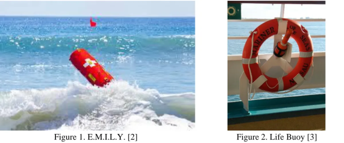
Figure 1 below shows an image of E.M.I.L.Y. (Emergency Integrated Lifesaving Lanyard). This lifesaving device is used to provide flotation, deliver life jackets, or pull a rescue line. E.M.I.L.Y. is remote operated and powered by a 1 kilo-watt jet pump, allowing it to reach speeds of up to 48 km/hr [2]. While E.M.I.L.Y. is a viable solution to rescue people that may be drowning, it is not automated and requires an operator to remotely control the device. Therefore E.M.I.L.Y. does not satisfy all the objectives for the SAVER project. However, it does have many qualities, that can be seen in Table 1, that could be useful for the SAVER project so it should be used as reference throughout the project.
Figure 1. E.M.I.L.Y. [2] Figure 2. Life Buoy [3]
Figure 2 above shows a classic life buoy ring. These rings are what one would expect to see on most maritime vessels that would be carrying people and have the potential for one or more of them to fall overboard. While the device is reliable and easy to use, it does not have any method propel itself towards a drowning victim and has the potential to be blown away by the wind very easily.
Figure 3 below shows an example of an ROV (Remotely Operated Underwater Vehicle) that are used to explore and research depths of the ocean while allowing the operator to be safely above water. While this device is not used to recue drowning victims, it is fully waterproof and allows for communication between the operator and the device despite the device being underwater. Both are potential aspects that could be useful for the final SAVER device.
Figure 4 above shows an example of a USV (Unmanned Surface Vehicle). This device operates without any user interference and is currently used for research purposes. The devices use various sensors like GPS and range finders to navigate and collision avoidance. These functions could be very beneficial to the final SAVER design and the team should research exactly how USVs utilize these sensors and implement similar designs in their device.
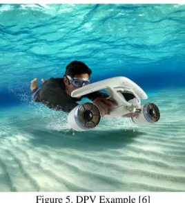
Finally, Figure 5 below shows an example of a DPV (Diver Propulsion Vehicle), often referred to as an underwater scooter. DPVs are fully submersible and are a reliable method to mobilize divers underwater. The devices consist of just a body for the operator to hold onto and some method of propulsion, typically propellers in an enclosure, that ensures the operator cannot injure themselves on the propeller. The propulsion system used in these devices could potentially be a way to give the SAVER device the propulsion that it needs that is waterproof and safe for operation.
Figure 5. DPV Example [6]
Table 1 contains descriptions and relevant information on the five existing products discussed above. The table also contains links to places to find more information on the products.
Table 1. Condensed Information on Five Existing Similar Products
Product Name Product Description Key Characteristics Link(s) to More Info
E.M.I.L.Y. [2]
Emergency Integrated Lifesaving Lanyard
-Deployed from Boat, Beach, or Aircraft
-Can Reach Top Speed of 48km/hr -Can Float up to Five People at Once
https://www.emilyrobot.com .au/key-features
Life Buoy [3]
Lifesaving Buoy to be Thrown to Drowning Person in Water
-Deployed from Boat, Beach, or Aircraft
-Very Fast to Deploy -Dependable
https://en.wikipedia.org/wiki /Lifebuoy
ROVs [4]
Remotely Operated Underwater Vehicles Used to Remotely Explore the Depths of the Ocean
-Totally Waterproof and Submersible
-Can Effectively Communicate with Operator on Surface -Collision Detection Underwater
https://oceanexplorer.noaa.g ov/facts/rov.html
USVs [5]
Vehicles that Operate on the Surface of the Water Without a
Crew -Completely Autonomous -Highly Reliable https://www.contracts.mod.u k/do-features-and- articles/usvs-the-maritime- future-of-unmanned-vehicles/ DPVs
[6] Diver Propulsion Vehicles
-Fully Waterproof and Submersible
-Reliable -Easy to Operate
2.4.2 Patents
Table 2 contains condensed information about five patents [6-10] that are relevant to the SAVER design project. These patents are things that have aspects related to the objectives of the SAVER team’s project that could be used as inspiration for the final SAVER design. It also serves as a reference to ensure no patents are violated when creating the SAVER final product. In addition to the patent number and link to the page where all the information was found, the table contains sketches associated with the patents and key characteristics specifically related to the SAVER project.
Table 2. Condensed Information on Five Relevant Patents
Patent Name Patent Number/Link Key Characteristics Image
Automated Fail-Safe Sea Rescue Flotation System [7] US6439941B2 https://patents.google.com/patent/ US6439941B2/en?q=automated&q =life+preserver&oq=automated+life +preserver -Satellite Radio -GPS Signal -Hydrostatic Pressure Detector Paired Motor System for Small
Boat Propulsion and Steerage [8] US5090929A https://patents.google.com/patent/ US5090929A/en?q=small&q=boat &q=motor&oq=small+boat+motor -Propulsion System -Used on Small Maritime Devices
A Kind of Overboard Target
Rescue Method and Search and Rescue System with Homing Function [9] CN109436247A https://patents.google.com/patent/ CN109436247A/en?q=homing&q= maritime&q=environment&oq=homi ng+in+maritime+environment
-Device Pulls Raft to Survivor -Fully Autonomous N/A Harness Assembly Having a Deployable Inflatable Life Raft Attached Thereto [10] US9205900B2 https://patents.google.com/patent/ US9205900B2/en?q=deployable&q =life+preserver&oq=deployable+lif e+preserver -Deployable Flotation Device Inside Harness -User deployed Unmanned Maritime Vehicle with Inference Engine and Knowledge Base and Related Methods [11] US20130282210A https://patents.google.com/patent/ US20130282210A1/en?q=unmann ed&q=maritime&q=vehicle&oq=un manned+maritime+vehicle -Unmanned Maritime Vehicle
2.4.3 Journal Articles
Table 3 contains condensed information about five journal articles that were consulted regarding ASVs currently in use in related applications as well as regarding several major design concerns. Most of these concerns are related to the sensing and/or programming aspects of the project, including which sort of sensors are optimal in which applications, how to process the data from said sensors (including dealing with noisy data), how to implement navigation/guidance/control (NGC) algorithms, and how to safely identify and approach a victim.
These articles have shown that there are a few proven ways of addressing these issues. A GPS, inertial measurement unit (IMU) or compass has been shown to work for long-range navigation, and radio or laser-based systems have been used for collision avoidance and detection. Potential-field navigation has been used effectively for multi-objective navigation as well as ensuring safe victim-approach speed. Kalman filtering and PID control have been used successfully to process noisy data and control the vehicle’s movement. Although the particular sensors and processes have not been selected yet, these articles provide a good variety of background research on autonomous surface vehicles and related technology.
Table 3. Condensed Information on Five Articles
Article Name Article Description Relevant Design Concerns Source Potential Field
Implementation for Move-to-Victim Behavior
for a Lifeguard Assistant Unmanned Surface Vehicle
[12]
This article explains a method by which a gradient on a potential
field can be defined to control speed and direction of an ASV navigating to a given GPS location
-Method of Obtaining Coordinates -Navigation Algorithm
-Speed Profile while Approaching Victim IEEE Navigation of unmanned marine vehicles in accordance with
the rules of the road [13]
This article explains a method of collision avoidance for ASVs in situations where multiple rules or objectives apply simultaneous and the ASV must choose best actions
-Coast Guard Collision Regulations
-Autonomous Operation with Multiple Objectives
-Detecting Collisions
IEEE
Obstacle Detection and Avoidance for an
Autonomous Surface Vehicle using a Profiling
Sonar [14]
This article explains multiple methods of autonomous collision avoidance as well as sensors used
in those methods
-Radar vs. Sonar vs. Lidar vs. Camera
-Above vs. Below Surface Sensors -How is Data Processed?
-Deciphering Object Movement vs. ASV Movement
IEEE
Basic navigation, guidance, and
control of an Unmanned Surface Vehicle
[15]
This article explains the operation of the NGC (navigation, guidance, and control) system on an ASV built around Kalman filters and
PID control
-How to Process/Filter Errors in Noisy Data
-How to Optimally Control the Motors of the Vehicle
-Which Navigation Sensors to Use
Autonomous Robot
Radar-Based Collision Detection Developments on
USV ROAZ II [16]
This article discusses several sensors and methods used to detect
collisions and discusses the design, building, and testing of a
radar/video collision detection system and the associated
challenges
-Collisions with Below-Surface Objects/Grounding
-Radio Antenna Positioning -Wave Occlusion and Water Reflectivity
-Target Tracking
2.4.4 Previous Projects/Case Studies
Table 4 below contains information on two case studies of previous projects that have addressed some of the major design concerns for SAVER. The first case study gives details on design and implementation of sensors and code for a similar application. The second case study gives details on the design and implementation of waterproof components, including waterproofing electronics and motors.
Table 4. Condensed Information on Two Projects/Case Studies
Article Name Article Description Relevant Design Concerns Source
Potential Fields Navigation of Lifeguard Assistant
Robot for Mass Marine Casualty Response [17]
This article is a senior project thesis that details the sensors, programming, and techniques used to turn EMILY into a fully
autonomous vehicle
-How to Implement Collision Avoidance in Tandem with Navigation
-How to Turn Vehicle Around if Starting on Wrong Heading
Senior Project Thesis from Texas A&M
Case Study from 2015 MATE International ROV
Competition [18]
This case study explains the design, building, and testing processes of an ROV built by
students at Hong Kong Polytechnic University, including
techniques and challenges in the design
-How to Waterproof Electronics -How to Waterproof Motor -Certain Components Extremely Expensive
MarineTech.org and Hong Kong Polytechnic University
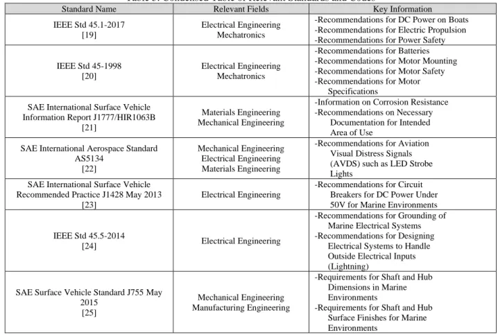
2.4.5 Relevant Standards and Codes
Table 5 below contains relevant standards and codes written by various organizations that could be referenced to ensure the SAVER device is up to code. Additionally, these codes should assist the team in making the SAVER device safer for everyone and understanding specifications and industry limitations.
Table 5. Condensed Table of Relevant Standards and Codes
Standard Name Relevant Fields Key Information
IEEE Std 45.1-2017 [19]
Electrical Engineering Mechatronics
-Recommendations for DC Power on Boats -Recommendations for Electric Propulsion -Recommendations for Power Safety
IEEE Std 45-1998 [20]
Electrical Engineering Mechatronics
-Recommendations for Batteries -Recommendations for Motor Mounting -Recommendations for Motor Safety -Recommendations for Motor Specifications
SAE International Surface Vehicle Information Report J1777/HIR1063B
[21]
Materials Engineering Mechanical Engineering
-Information on Corrosion Resistance -Recommendations on Necessary Documentation for Intended Area of Use
SAE International Aerospace Standard AS5134
[22]
Mechanical Engineering Electrical Engineering Materials Engineering
-Recommendations for Aviation Visual Distress Signals (AVDS) such as LED Strobe Lights
SAE International Surface Vehicle Recommended Practice J1428 May 2013
[23]
Electrical Engineering
-Recommendations for Circuit Breakers for DC Power Under 50V for Marine Environments
IEEE Std 45.5-2014
[24] Electrical Engineering
-Recommendations for Grounding of Marine Electrical Systems -Recommendations for Designing Electrical Systems to Handle Outside Electrical Inputs (Lightning)
SAE Surface Vehicle Standard J755 May 2015
[25]
Mechanical Engineering Manufacturing Engineering
-Requirements for Shaft and Hub Dimensions in Marine Environments
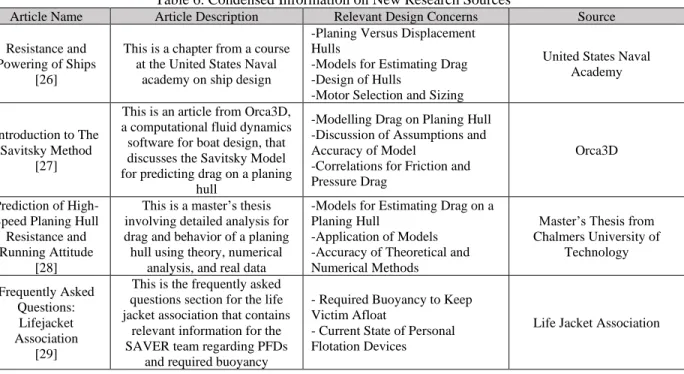
2.4.6 Ongoing Research
The following table contains information about all research done since the Scope of Work in order to finalize the design. As more research is completed, sources should be added here.
Table 6. Condensed Information on New Research Sources
Article Name Article Description Relevant Design Concerns Source
Resistance and Powering of Ships
[26]
This is a chapter from a course at the United States Naval
academy on ship design
-Planing Versus Displacement Hulls
-Models for Estimating Drag -Design of Hulls
-Motor Selection and Sizing
United States Naval Academy
Introduction to The Savitsky Method
[27]
This is an article from Orca3D, a computational fluid dynamics software for boat design, that discusses the Savitsky Model for predicting drag on a planing
hull
-Modelling Drag on Planing Hull -Discussion of Assumptions and Accuracy of Model
-Correlations for Friction and Pressure Drag
Orca3D
Prediction of High-Speed Planing Hull
Resistance and Running Attitude
[28]
This is a master’s thesis involving detailed analysis for drag and behavior of a planing hull using theory, numerical
analysis, and real data
-Models for Estimating Drag on a Planing Hull
-Application of Models -Accuracy of Theoretical and Numerical Methods
Master’s Thesis from Chalmers University of
Technology Frequently Asked Questions: Lifejacket Association [29]
This is the frequently asked questions section for the life jacket association that contains
relevant information for the SAVER team regarding PFDs
and required buoyancy
- Required Buoyancy to Keep Victim Afloat
- Current State of Personal Flotation Devices
3.0 Objectives
This chapter defines the scope of the project, including goals, evaluation criteria, and deliverables. 3.1 Problem Statement
Search and rescue teams need a way to get help to drowning individuals quickly and safely without increasing risk, endangering rescue members, or consuming unneeded manpower because current methods are too slow and unreliable. A method to assist a person at risk of drowning with a flotation device without requiring a member of a rescue team to deliver the flotation device directly would decrease the manpower required to save a person at risk of drowning. Additionally, it decreases the amount of time it would take for the person in need to be assisted and allows someone to be rescued even if SAR teams do not have a direct line of sight to that individual that fell overboard. 3.2 Boundary Sketch
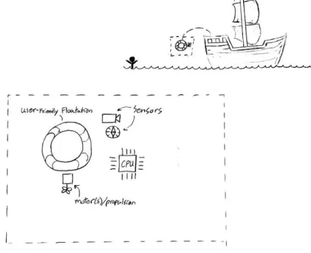
Figure 6 is the boundary sketch of the problem. The boundary sketch was created to help the team understand the scope of the problem visually and show what is anticipated to be needed for the project. The boundary sketch also helps to quantify what can be changed (within the dashed boundary) and what is not able to be changed (everything outside of the dashed boundary). The most notable factors that are out of the control of the project is the boat that the project would be thrown off, the body of water the project is in, and the relative location of the person in need to the boat. These factors should heavily influence the design of what is inside of the boundary. Inside of the boundary are the parts of the design that are thought to be needed to satisfy the problem statement. These include the flotation device, sensors, propulsion, and CPU. The flotation device is needed to achieve to goal of assisting the person in need by supplying a way for them to float without exerting large amounts of energy. The flotation device should need to be large enough to keep the person in danger afloat and be ergonomically designed for the person in danger to use/grab hold of easily. The method of propulsion should need to be powerful enough to get the project to the person in danger in a reasonable amount of time and not be overpowered by the flow of the water. The propulsion should also need to be efficient enough to get the project to the person in danger without running out of power. Sensors of multiple types should be needed to measure location, speed, acceleration, and other parameters that are needed to accurately control the project. The sensors should be read and analyzed by a CPU. The CPU should also control the propulsion and steering to get the project to the desired location (the person).
3.3 Customer Wants/Needs
The customer defined in the problem statement included maritime rescue teams. For a rescue team the project should need to be efficient enough to increase the effectiveness of a rescue and not get in the way of their saving people in danger. Although rescue teams can benefit from assistance in maritime rescues, the end goal is also to create a project that would mitigate, at least temporarily, the need for a maritime rescue team. This would mean that the project should be designed for use by a person who has no rescue experience, and at the most has minimal training with using this project. For a more commercial customer, usability and reliability are important aspects of the projects because of the amount a commercial customer would depend on the project to replace a rescue team. A House of Quality analysis of customer needs and wants can be found in Appendix A.
3.4 QFD Results and Solution Specifications
The QFD House of Quality is a document generated by the SAVER team to determine an appropriate list of specifications for their design. To generate the QFD House of Quality, a list of all potential users (manufacturers, search and rescue teams, victims, etc.) and important device attributes for each potential user were generated. Then, the importance of each attribute to each user was assigned a weighting in order to determine overall importance of each attribute. A list of device specifications was then generated to ensure that each attribute is accounted for in the final design as well as a target for each specification. The completed document generated by the team can be found in Appendix A.
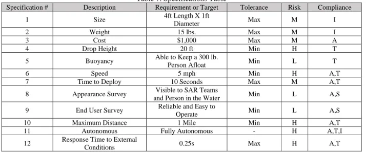
Contained in Table 7 below is a relevant description, requirement or target, tolerance, risk, and compliance for each of the specifications. The description states what the specification is. The requirement or target states what the team is hoping to accomplish with that specification. Tolerance is how well the team must hit the requirement or target values. Risk is how difficult the team believes it should be to achieve the requirement or target value. Finally, compliance is the method in which the team plans to determine whether they have reached the required or targeted values. These methods are through Analysis (A), Test (T), Similarity to Existing Designs (S), or Inspection (I).
The rationale for the targets is that a person who witnesses a man-overboard scenario should be able to react to the situation as quickly and easily as possible, that it should be possible to deploy the device from a large boat, that the device should reach the victim within a reasonable time, and that the device should work well for virtually all victims.
Table 7. Specifications Table
Specification # Description Requirement or Target Tolerance Risk Compliance
1 Size 4ft Length X 1ft
Diameter Max M I
2 Weight 15 lbs. Max M I
3 Cost $1,000 Max M A
4 Drop Height 20 ft Min H T
5 Buoyancy Able to Keep a 300 lb.
Person Afloat Min L T
6 Speed 5 mph Min H A,T
7 Time to Deploy 10 Seconds Max M A,T
8 Appearance Survey Visible to SAR Teams
and Person in the Water Min L A,S
9 End User Survey Reliable and Easy to
Operate Min L A,S
10 Maximum Distance 1 Mile Min H A,T
11 Autonomous Fully Autonomous - H A,T,I
12 Response Time to External
The following list enumerates the team’s 13 chosen design specifications and their exact meaning.
1. The size of the design refers to the volumetric space which the SAVER device should encapsulate. 2. Weight encompasses the entire weight of all internal components, the frame, and any externally attached
features for the drone.
3. Cost includes only the cost of all the components on the final SAVER device.
4. Drop height pertains to the maximum distance that the device can fall without sustaining permanent damage.
5. Buoyancy relates the maximum external weight that the device can support in water while remaining afloat. 6. Speed references the maximum speed at which the SAVER device should be able to travel.
7. Time to deploy describes the time for the SAVER device to orient itself in the water and begin actuation after being thrown overboard.
8. The Appearance Survey should be utilized for data collection on whether the drone is visible by SAR teams and nonthreatening for those being rescued.
9. The End User Survey should utilize feedback from operators of the drone pertaining to ease of use and operation.
10. Maximum distance enumerates the distance the device should be able to travel
11. Autonomous prescribes the SAVER device as a fully autonomous device with no active human navigation, and no prior experience required for operation.
4.0 Concept Design
This chapter describes the design process that the team performed to select their chosen design direction and provides a thorough description of the chosen concept design and possible risks and challenges the team would have to overcome when designing the SAVER device.
4.1 Processes
The process for choosing a final design had five distinct phases: function decomposition, ideation, concept models, Pugh matrices, a morphological table, and a decision matrix. All these processes, as well as the results for SAVER, are described below.
4.1.1 Function Decomposition
The aim of function decomposition is to break down the requirements of a given problem into several basic functions. This makes it easy to identify critical aspects of the solution while staying open to many solution possibilities. The functions that the SAVER vehicle must satisfy are as follows:
1. Propel itself
2. Turn on and connect to networks automatically 3. Be safe
4. Find the victim
5. Float and support victim 6. Be easy to use
7. Be obvious to rescuers and victim
8. Take a large drop into water without damage 9. Be waterproof
4.1.2 Ideation
The aim of ideation is to generate as many solutions for each function as possible. This allows exploration of many ideas so that the best solution can be found. The SAVER team performed various ideation methods for several critical functions. This allowed the team to rapidly generate as many ideas as possible, without regard to feasibility. Although there are many possible functions that could be ideated for, the team focused their efforts on just three: hull/frame construction, flotation, and drive design. The reasoning for this was that these concerns were the most relevant: many functions, such as waterproofing or power system, are directly informed by the design of the physical body and drive system, and others, like electronics or code design, are irrelevant if there is not first a functioning physical prototype. For a list of the most feasible ideas generated for these three functions, see Appendix B.
4.1.3 Concept Models
Building concept models allows exploration of ideas generated during the ideation phase and can often lead to insights or realizations about certain designs. On the designated concept model build day, the SAVER team brought a wide variety of crafting materials to produce as many concept models as they could. Many concept models were built using these various crafting supplies. Photos of these concept models can be found in Appendix C and are intended to be possible solutions to various aspects of the SAVER device. These concept models assisted in taking the multitude of ideas generated during the ideation phase and narrowing down towards the ideas that are most likely to produce a successful drone design.
4.1.4 Pugh Matrices
ultimately pared down the options from ideation and helped the SAVER team to determine which solutions would be put in a Morphological Table.
4.1.5 Morphological Table
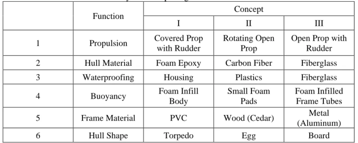
A morphological table allows for combinations of many designs from subsets of component designs that satisfy given functions. The reason that the top design for each function is not always picked is that the overall design has many complex interplays between components and the best overall combination is not always the sum of each best design for each function. Table 8 below contains the top three ideas taken from the Pugh Matrices for each of the six functions that the team created Pugh Matrices for.
Table 8. System Morphological Table for SAVER
Function Concept
I II III
1 Propulsion Covered Prop
with Rudder
Rotating Open Prop
Open Prop with Rudder
2 Hull Material Foam Epoxy Carbon Fiber Fiberglass
3 Waterproofing Housing Plastics Fiberglass
4 Buoyancy Foam Infill
Body
Small Foam Pads
Foam Infilled Frame Tubes
5 Frame Material PVC Wood (Cedar) Metal
(Aluminum)
6 Hull Shape Torpedo Egg Board
First in the table is the propulsion function. The top three concepts the SAVER team decided between were a covered propeller with a rudder, a rotating open propeller, and an open propeller with a rudder. The covered propeller with the rudder is the safest of the three but should likely have the least thrust. The rotating open propeller would give more propulsion but is much less safe to the victim in the water. And finally, the open propeller with a rudder is not quite as dangerous as the rotating open propeller but gives slightly more propulsion than the covered propeller design.
Regarding the hull material, the SAVER team determined that the top three options would be a foam epoxy, carbon fiber, and fiberglass. The foam epoxy would be the lightest and most buoyant of the three but not as sturdy. The carbon fiber is the sturdiest of the three and relatively light, however, it is easily the most expensive of the three and would be relatively difficult to manufacture. Lastly, the fiberglass would be cheap and not too difficult to manufacture but is heavy and not very sturdy. Note that each material is the hull/surface material, not the inner body material, so it possible to have epoxy over foam or fiberglass over foam. Surfboard construction techniques have also been investigated, and while fiberglass over foam is the classic method of surfboard construction, modern-day surfboards also are frequently made from epoxy.
Next in the table is the method in which the SAVER team plans to waterproof the device. The first option is a waterproof housing around the electronics that would have waterproof connectors extending from the housing to sensors and motors. This gives the option to open the container and manipulate the electronics within but has the highest risk of a leak. The second option is a plastic that could encase the electronic components so that it would not be possible for the water to reach the electronics. While this is by far the best way to ensure the electronics never get exposed to water, it makes it very difficult for the SAVER team to manipulate the electronics after setting the plastic. This means that this method would more likely be used on a final product as opposed to the prototype. The third method discussed was using fiberglass to waterproof the device, by layering the fiberglass over the electronics, essentially sealing the electronics within the fiberglass. Ultimately this method would provide great waterproofing but the manufacturability of this makes it difficult to produce on a prototype.
itself to be narrow but might make it difficult to supply adequate buoyancy to the victim. Lastly, the foam infill tubing would not add any volume to the SAVER device but wouldn’t supply as much buoyancy as the other options.
The fifth function discussed in the table above is the frame material. The top three options considered were PVC, cedar, and aluminum. The PVC was considered because it is a light and cheap material but might not be quite as sturdy as the other two options. Cedar was also considered as it is easy to manufacture, and various kinds are buoyant, but cedar is also very heavy compared to PVC. Lastly, aluminum was considered which would be by far the sturdiest of the three options, but also likely the heaviest and most expensive.
The final function considered in the system morphological table is the hull shape. Initially, the top three considered body shapes were a torpedo shape, an egg like shape, and a surfboard like shape. Pictures of these general body shapes of these designs are shown in Appendix E. The torpedo shape is considered because it is easy for the victim to grasp onto in the water, however, it isn’t the sturdiest shape as it has a long flat edge that, if landed on, has a high potential to crack the hull or frame. The egg shape was also considered because it is the sturdiest of the three options, but likely would have the lowest maneuverability. Finally, the last body shape considered was the surfboard shape that would allow the person to lay on top of the device to be buoyant but had a high risk of landing on the top with the motor up, rendering the SAVER device useless.
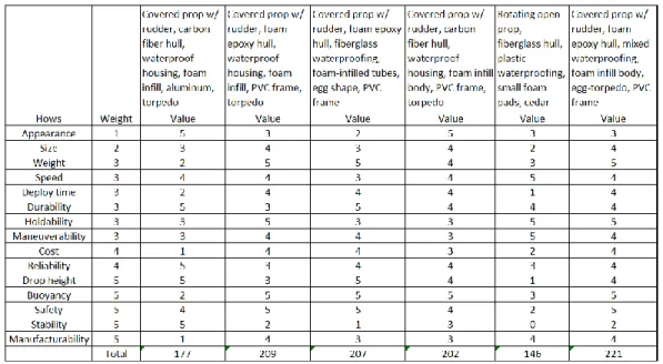
4.1.6 Decision Matrix
For the final decision matrix, each team member selected a combination of component functions for a complete design that they thought would work well. In addition, a design consisting of all top components was included. These combinations ultimately would make up the top five alternative design ideas. The exact specifications of each of these combinations can be seen in the first five elements of the top row of the weighted decision matrix below. After the decision matrix values were computed with these five combinations, the team considered whether blending or altering existing designs could create an even better design. Most of the combinations had similar final values, but while going through the process, the team was able to see which aspects were more beneficial to overall performance. This led to the creation of a new blended design which included the best parts from each of the others. This combination is seen on the right side of the top row in the weighted decision matrix below, that has the highest overall score and thus would ultimately become the selected concept design. (Note: as of February 2020, due to new design considerations and discussions with the project sponsor, the chosen design has evolved considerably – see notes on sections below or section 5.0 which describes the final planned design in detail)
The judgment criteria are ordered from least important to most important. The aspects considered least important were appearance, size, and weight, as these aspects do not directly affect the performance of the device. More important aspects include those related to non-critical performance, such as speed, time to deploy, durability, maneuverability, etc. The most important aspects are those that are critical to performance, including whether the device can survive a large drop, whether it can self-right in the water upon landing, whether it is buoyant enough to support a person, and whether it is safe. The cost and manufacturability of the device are also valued highly, primarily because the team is limited in resources, but secondarily because one of the main advantages this device has over its competition is affordability.
4.2 Selected Concept
The new blended design was selected, as it outscored the other designs in the weighted decision matrix. This was because the blended design has the best balance of desirable characteristics: safety, efficiency, cost, ease of construction, speed, strength, reliability, etc. (Note, again, that as of February 2020, the chosen design has evolved considerably – see notes on subsections below or section 5.0 which describes the final planned design in detail)
4.2.1 Structural Design
The proposed design used a PVC frame with foam walls and infill with an epoxy finish molded into the shape that was both rounded and elongated (a combination of the egg and torpedo designs). This component design considered weight, cost, ease of construction, strength, performance, durability, and safety.
As of February 2020, the structural design had changed considerably due to new information found through research and discussions with the project sponsor. The hull shape was made more similar to a speedboat due to planing considerations (see section 5.2.2). The frame was changed to be made from medium-density fiberboard (MDF) and the hull from fiberglass for cost and manufacturing considerations.
4.2.2 Power and Drive Design
The proposed design used a single propeller driven by an electric motor, covered for safety considerations, with a rudder to turn. This design considered efficiency, safety, cost, performance, and ease of implementation. The team intended to buy these systems premanufactured.
4.2.3 Electronic Systems Design
The proposed electronic systems design used a master microcontroller which was connected to all sensors and two slave microcontrollers which each would drive one of two motors. These should all be interfaced through a printed circuit board (PCB), that the team should design. The first motor is the main motor which drives the propeller, and the second is a smaller servo motor which actuates the rudder. The reason each motor has its own microcontroller is that highly controlled electric motors have large computational demands and it should likely be easier and safer to delegate the complex tasks of motor reading and control to their own chips. The sensors that the master microcontroller should integrate with include a GPS transceiver, a radio direction finder, an inertial measurement unit, and a moisture detector. The master microcontroller should also drive a strobe light for nighttime visibility.
As of February 2020, the electronics system was simplified and no longer included a custom PCB, the two slave microcontrollers, or the radio direction finder, moisture sensor, or strobe light.
4.2.4 Control/Code Design
4.2.5 Concept Prototype
The team’s concept prototype was focused on frame design, as it was unclear how difficult it would be to fabricate a PVC frame or if a certain heating and bending process to shape the frame would degrade the structural integrity of the PVC. The SAVER team created this prototype by using a heat gun to heat various length PVC pipes close to their melting point so they would be malleable. The PVC pipes were then bent into the desired shape by hand and allowed to cool in that position, thus locking in their new bent shape. The conclusion drawn from this prototyping process is that PVC is a promising option, offering excellent weight, structural soundness, and ease of fabrication at an extremely low cost. This process could be altered to get much more precise shapes by making a jig out of much more sturdy material through machining or casting. These jigs could then be used to bend the PVC pipe to a precise shape instead of doing it by hand. After discussing with the project sponsor however, the team opted for an MDF frame due to manufacturing considerations.
Figure 8. Concept Prototype
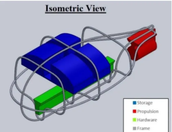
4.2.6 CAD Model
The team’s CAD model was meant to help visualize the chosen model more accurately than the concept prototype. The focus of the CAD model was to show the final shape of the frame and where key components were located.
The frame shape was chosen to allow for maneuverability and control when moving through the water while still being easy for a victim to hold on to. Higher density components were located lower in the frame to increase stability. The top portion was designed to be bulbous to supply the needed buoyancy to support a person and to contain the storage for the anticipated safety accessories. These accessories include a radio, freshwater, and a flair kit. The propulsion is located at the back and is enclosed to minimize the likelihood of injury. The size and shape of each component is not finalized so all shapes are meant to be rough representations.
As of January 2020, the shape of the hull had been redesigned due to planing considerations (see section 5.2.2). Additionally, the team opted to design separate top and bottom components, for design flexibility, cost, and manufacturing reasons. It was also decided that the top portion would no longer have a compartment to store supplies in, although this could be a good feature to implement in future design iterations.
4.3 Preliminary Analysis
This section describes the preliminary hand calculations completed by the SAVER team to begin the parameterization of components to meet design specifications.
4.3.1 Drop Height
One of the most important design considerations for the SAVER device was the height from which it could be dropped. The design specifications call for the device to be capable of withstanding a 20-foot drop on deployment. This drop corresponds to the maximum force that the device should be able to withstand while maintaining structural integrity. Appendix F contains the full hand calculations for determining the value of the impact force. The result is the equation:
𝐹𝑖𝑚𝑝=
𝑀𝑏𝑜𝑡√(𝑣2𝑥𝑚𝑎𝑥)2+(𝑔ℎ1+(𝑣1𝑦𝑚𝑎𝑥)2)2
𝛥𝑡 (Equation 4.1)
Equation 4.1 relates the impact force to the required drop height, estimated maximum deployment velocity, mass of the device, and the impact time. The most undefined variable in the final equation is the impact time which has been conservatively estimated as 0.1 seconds. The equation yields an impact force of 5.43 kN. This force should be utilized for FEA on the CAD model to determine the best member thicknesses for sustaining the impact force while maintaining a low mass and similar body shape.
4.3.2 Buoyancy
The SAVER device is required to navigate to people who fall overboard and remain in their vicinity to provide a flotation device. In order to accomplish this task, the SAVER device must be capable of being buoyant on its own as well as buoyant enough to support the weight of the person being rescued. Appendix F contains the full hand calculations for determining the design parameters that affect the buoyancy of the device. The final equation is:
𝜌ℎ𝑤𝐿 = 𝑀𝑝+ 𝑚 (Equation 4.2)
Equation 4.2 develops a relationship between the density of saltwater, the device dimensions, and the mass of the device for providing a buoyant device to a 350-pound person. In determining preliminary dimensions of the device, this equation should calculate the height of the robot that should need be under water for it to remain buoyant. 4.4 Risks and Challenges
This section describes the aspects of the SAVER design that the team determined to be highly risky or challenging, and how the team planned to handle these aspects. A full design hazard checklist can be found in Appendix G.
4.4.1 Propeller Safety
4.4.2 Waterproofing and Electrical
Operating an electrical device in an aquatic environment leads to potential for the electrical circuitry to be exposed to the water. This can cause accidental discharges from the battery which can damage the device and possibly electrocute anyone near the device in the water. The team should has done much research into methods of preventing accidental discharges. Originally, the team planned on placing a very large ground plane covered in an insulating material in the device so the battery should discharge into the ground plane and not the water. The team also considered using a fuse to ensure that there is no rapid discharge from the battery. Various codes and standards, including but not limited to the SAE International Surface Vehicle Recommended Practice [22] and IEEE Std 45.5-2014 [23], should be used as reference to ensure that the device is up to code and safe for all users.
In February, the team met with a campus electrician to discuss the proposed design and any electrical hazards. The electrician noted that at voltages less than 50 V, electrocution was not much of a hazard, and at that at voltages less than 24 V, the danger was almost negligible.
4.4.3 Navigation
The SAVER device should autonomously approach the person in the water – this is one of the more challenging aspect of the design. Autonomous navigation in a maritime environment is inherently difficult for many reasons. These reasons include but are not limited to, accuracy of sensors making it difficult to locate the victim, difficulty mapping a path to where the victim is, and drift throwing the vessel off course during its journey. Additionally, there is an inherent risk of the device not stopping or slowing properly and running into the victim’s head in the water. If the device is traveling at a high speed, this impact could injure the person in the water or even knock them unconscious if the device is traveling fast enough. In order to minimize these risks, the SAVER team chose appropriate sensors and did their best to design the code and sensors to slow the device as it approaches the victim in the water. In order to ensure that this function is safe, much testing should be done on the device when the final build is completed. On top of this, the device should be light and soft enough so that even if the device impacted the person floating in the water at a relatively high rate, there is little chance of severe injury or knocking them unconscious.
4.4.4 Shelf Life
5.0 Final Planned Design
This chapter outlines the SAVER team’s final planned design as well as the rationale and analysis driving many of the team’s design choices. It should be noted that the final design was intended to be a proof of concept, however, throughout this chapter, there are many potential improvements noted that could be made in the future if the prototype were to be adapted into a production model.
As of April 2020, Cal Poly’s campus had shut down due to the COVID-19 pandemic, and all work was being carried out remotely. Without access to labs or shops, the team could not complete the physical build as intended, and the project underwent major scope changes. The project scope change, as well as all work that was able to be completed, is outlined in chapters 6 and 7. Please note that the final design described in this chapter reflects the planned design before this scope change, and not the work that the team was actually able to complete.
5.1 Overview and Functionality
The main function of the SAVER bot is to save people who have fallen overboard, and thus it is important that the device operates autonomously, can move to the victim in a timely manner, and provides adequate support once it arrives. These functions are met through:
1. A structural design that is ergonomic and supportive, yet strong and efficient at moving through the water
2. Power and drive systems that are safe yet provide adequate thrust and turning capability 3. An electronics system with the necessary sensors and controllers to allow the bot to navigate
autonomously
4. Implementation of C++ code to collect sensor data, run the SAVER device control scheme, and actuate a drive thruster and rudder motor to control direction
Figure 10 below shows an exploded view of the SAVER device’s final design. The design is approximately 4 ft long by 2 ft wide by 2 ft tall. The major components represented are the fiberglass hull and cover (dark grey), foam top piece (light grey), MDF frame (brown), thruster assembly (black), strengthening aluminum plate (grey), batteries and assorted electronics (blue), electronics enclosure (white), and rudder assembly (green). Each of these components are described in further detail in the following chapters, including design, manufacturing, and integration into the final SAVER device. Figures 11 and 12 illustrate the integration of major components with the fiberglass hull from the top and bottom views, respectively. Note that in these views, the sealing plate and top foam assemblies are hidden so that component location within the hull can be seen.
Figure 11. Top View of Assembled Hull Figure 12. Bottom View of Assembled Hull
5.2 Structural System
This section outlines the structural design of the SAVER device, including the hull shape, materials, design, construction, and waterproofing. Generally, the structural portion consists of a frame mounted inside a fiberglass hull, which is then filled with foam and sealed with a sealing plate. Each of these components are discussed in the following sections. For a complete drawing package, see Appendix J.
5.2.1 Frame Shape
MDF (medium density fiberboard) was chosen as the internal frame material due to ease of manufacturing and ability to iterate on the design. Note that this material is great for the proof of concept design but would not be ideal for a final product, as MDF does not perform well in water. The frame should help maintain the rigidity of the hull and allow for easy mounting of critical components on the interior of the hull. More details on the frame, including manufacturing and assembly instructions, can be found in section 8.2.1 and in Appendix J.
Figure 13. Frame Shape
5.2.2 Hull Shape
Figure 14. Isometric View of Hull Figure 15. Side View of Hull
5.2.3 Materials
The internal frame should be made of MDF. This material was chosen because it is resilient against compressive forces, while also having some flexibility in the shear direction. This flexibility allows the frame to be bent and “snapped” into place to allow for the desired shape and rigidity of the frame. While lots of different materials have similar properties, MDF is inexpensive and can be manufactured into the desired shape using resources available on Cal Poly’s campus, which is ideal for prototyping.
For initial prototyping, the bottom shell should be made of fiberglass. The bottom shell needs to be sturdy and hydrodynamic, as it is the surface of the SAVER device that should be in contact with the water. Fiberglass was chosen, as it can be manufactured, by laying it up into a mold, to have curved irregular shapes. In order for the SAVER device to plane, the design needs this sort of curved shape. The full process for manufacturing the hull is outlined in section 8.2.2. In anticipation of higher stress regions in the hull, the SAVER team has integrated additional strengthening members. These additional members should be composed of aluminum plates to distribute the load.
The top shell should be made of pourable polyurethane foam. The foam shape shown in Appendix J contains the final design with ergonomic requirements taken into consideration. The chosen pourable polyurethane foam should be an easy to use foam that provides the necessary 15 pounds of buoyancy force [29].
5.2.4 Design and Construction
Initial designs for the SAVER device have been documented in SOLIDWORKS. Iterations of the frame have been tested using simple prototypes laser-cut from MDF. Final pieces for the frame should be made using a jig saw. The fiberglass shell should be laid up in a mold made of foam using a CNC mill in the Cal Poly shop. Excluding the molding process, all the construction should be done manually. More about this should be covered section 8.2 on manufacturing. For a complete drawing package including dimensions see Appendix J.
5.2.5 Waterproofing
Since the bottom shell is to be made from a fiberglass layup, it should be inherently waterproof. The top foam should be made from the pourable polyurethane foam, which is not inherently waterproof, but is resistant to the absorption of water. If the polyurethane is continuously submerged for months at a time, this can lead to losses in buoyancy, but continuous submersion is not intended as part of the use for the SAVER device. This means that if the SAVER device is stored properly, the polyurethane should function as if it is waterproof for these purposes. To include an additional layer of waterproofing, the sealing plate was added between the top foam and the hull. The sealing plate will contain a rubber gasket inside of the ring of clamping bolts to prevent water from seeping in between the sealing plate and the hull.
5.3 Thruster and Rudder Systems
This section outlines the thruster and rudder systems of the SAVER device, including reasoning behind the chosen design and how the components were selected.
Figure 16. Isometric View of Integrated Thruster and Rudder Systems
5.3.1 Thruster System
For the drive system, a premanufactured integrated thruster system was selected which has the motor, propeller, and housing all together in one waterproof package. The unit selected was the T200 Thruster from BlueRobotics, the technical documents for which can be found in Appendix L. This thruster delivers more than the needed 425 watts at 18 V, which is discussed in section 5.6.1 Fluid/Power Calculations. The thruster should be mounted on the bottom aft end of the boat to allow the thruster to remain underwater while the craft is planing. The motor component of the thruster is controlled with an Electronic Speed Controller (ESC) by the code implementation discussed in section 5.5. This should enable variable boat speed depending on the craft’s distance from the victim. Foreign material such as kelp or fishing line fouling the prop would be a concern in real-world application, but in order to focus on developing a working proof-of-concept, the team opted to leave this issue to future design iterations.
5.3.2 Rudder System
A modified surfboard fin was to be be used for the rudder, as it would have the right amount of surface area and was already an optimized control surface. The fin would be turned by a DC servo motor – the model selected was the 26 RPM Premium Planetary Gear Motor w/Encoder from ServoCity. A link to the product literature can be found in Appendix L. With a gear ratio of 455:1, the selected motor can output 583 oz-in of torque at stall at only 12V and 4.9A. This is a very large torque (slightly exceeding the specifications determined in section 5.6.1) for a relatively small amount of power, which is ideal for the purposes of this project. The rudder should be mounted aft of the thruster, set into the cavity on the back of the bottom fiberglass hull, to allow for optimal redirection of the higher velocity fluid, leading to more efficient redirection of the propeller wash and more precise turning.
The rudder motor should be fixed inside a small length of ABS pipe with a sealed bearing on one end to allow the shaft of the motor to extend outside the ABS pipe while remaining waterproof. The enclosure should be fixed to the hull via ¼ in x 20 screws and nuts through the top of the ABS pipe. To attach the fin to the rudder motor, the team should acquire a 4 in x 1 in x ¼ in piece of scrap metal from the Cal Poly machine shops and drill threaded holes in the metal so a simple set screw hub can be set on the shaft of the motor and attached to the piece of metal. Finally, the team should drill two more holes in the piece of scrap metal for the two protrusions from the fin, as seen in Figure 19, so that the fin can be slotted into the metal and fixed with hardware from Home Depot.
The whole system should be integrated by gluing the fin to the metal plate, putting the set screw hub on the rudder motor shaft, bolting the set screw hub to the aluminum using 4 #6-32 screws, nuts, and washers from Home Depot, and attaching the ABS to the hull via ¼ in. x 20 screws through the top of the ABS pipe. The ¼ in. X 20 screw heads and a washer should be on the inside of the ABS pipe with PL Marine Loctite between the screw and ABS pipe. The ¼ in. X 20 nuts and washer should be on the inside of the hull with PL Marine Loctite around the screw on the inside and outside of the hull.
Figure 18. ServoCity 26 RPM Planetary Gear Motor [31] Figure 19. Surfboard Fin to be Used as Rudder
Figure 20. Set Screw Hub for Rudder Motor [31] Figure 21. Sealed Bearing [32]
5.4 Electronics Systems
This section outlines the design of the electronics systems for the SAVER device and the motivation behind these design decisions.
5.4.1 Wiring Diagram
Figure 24 shows a simplified wiring diagram for the SAVER bot. As seen below, the design is centered around the microcontroller that is running the receiver end of the GPS system. The SAVER prototype uses an Adafruit Feather M0 RFM96 LoRa board provided by the sponsor Dr. Ridgely. This board has an Atmel ATSAMD21G18 microcontroller which functions as the “brain” for the entire system. This microcontroller operates all the components outlined in the diagram above using the various tasks outlined in section 5.5.1 Task Descriptions.
Figure 24. Wiring Diagram
![Table 2 contains condensed information about five patents [6-10] that are relevant to the SAVER design project](https://thumb-us.123doks.com/thumbv2/123dok_us/8220347.2179420/15.918.110.813.285.1053/table-contains-condensed-information-patents-relevant-saver-project.webp)