OTTER VECTOR EXTENSION
Senior Project Report
California Polytechnic State University,
San Luis Obispo
In Partial Fulfillment
of the Requirements for the Degree
Bachelor of Science in Computer Engineering
by
Alexis Peralta
c 2020 Alexis Peralta
TITLE: Otter Vector Extension
AUTHOR: Alexis Peralta
DATE SUBMITTED: June 2020
ADVISOR: Joseph Callenes-Sloan, Ph.D.
ABSTRACT Otter Vector Extension
Alexis Peralta
TABLE OF CONTENTS
Page
LIST OF TABLES . . . vi
LIST OF FIGURES . . . vii
1 Vectors in Computer Architecture . . . 1
1.1 Related Work . . . 2
2 OTTER RISC-V Vector Extension Overview . . . 4
2.1 Vector Terminology . . . 5
3 OTTER Vector Extension Implementation . . . 6
3.1 Vector Configuration . . . 6
3.2 Vector Register File . . . 7
3.2.1 Vector Masking . . . 8
3.3 Vector Loads and Stores . . . 9
3.3.1 Vector Memory Assist . . . 9
3.4 Vector Algorithmic Logic Unit . . . 11
4 Results & Analysis . . . 13
5 Future Work . . . 21
BIBLIOGRAPHY . . . 23
APPENDICES A . . . 25
LIST OF TABLES
Table Page
2.1 SEW vtype encoding . . . 5
4.1 Array Addition Speedup Results . . . 16
4.2 memcpy Speedup Results . . . 20
LIST OF FIGURES
Figure Page
3.1 Vector length and SEW CSRs . . . 6
3.2 Vector layout in VRF . . . 7
3.3 VRF . . . 7
3.4 Example of a vector mask stored at v0 . . . 8
3.5 Vector Memory Assist Unit . . . 10
Chapter 1
VECTORS IN COMPUTER ARCHITECTURE
Vectors provide inherent data-level parallelism and appear frequently in high-performance computing[10]. Vectors provide support for algorithms used in many naturally-vectorizable applications such as multimedia extensions and processing, ”human-machine” interfacing, sound and image processing, wireless communication, bioin-formatics, climate modeling, cryptography, game consoles, graphics processing, and much more [8, 5, 2, 11, 7]. The advantages of modern vector architectures even exceed superscalar architectures for many of the aforementioned applications which exhibit an emphasis on computing [8]. They are also often less complex to contruct and scale with CMOS technology compared to superscalar computers [8].
per-of arithmetic computations[8]. Vector architectures are easily programmable and highly flexible while also contributing power and performance metrics rivaling cus-tom designs[8]. Vector instruction sets allow the programmer to maintain sequential ordering while achieving performance increases from data-parallel operations[6]. Be-cause vector architectures are programmable, fabricated versions can be re-purposed in different applications[11].
RISC-V International is in the process of developing a ”RISC-V ’V’ Vector Extension” to bring SIMD instructions to the RISC-V instruction set[9]. Up until the appear-ance of RISC-V, most widely used architectures, primarily chips from Intel and ARM, remained proprietary[4]. The introduction of the free, open-source RISC-V instruc-tion set architecture brought unprecedented flexibility to the computing industry[4]. This paper presents an implementation of a subset of the v0.7.x proposed ”RISC-V ’V’ Vector Extension” instructions. All implementation was completed using System Verilog and Vivado Design Suite for the BASYS3 Artix-7 FPGA.
1.1 Related Work
implements pipe-lining within its functional units[6]. Another vector architecture, ”CODE”, utilizes a clustered vector register file rather than a centralized vector reg-ister file[8]. The OTTER Vector extension follows precedents like VIRAM, Tarantula, and AltiVec and opts for a single centralized vector register file, but a single integer functional unit for simplicity[8]. This implementation is meant to be less complex without hindering performance.
With regards to memory, this implementation has variable alignment requirements for increased flexibility. Predecessors like AltiVec and SSE have strict memory alignment constraints[7, 2]. The Spert-II vector microprocessor enables unit-stride, strided, and indexed loads and stores, as does this implementation[11]. This implementation con-tains a load/store unit to handle vector memory operations, characteristic of several vector-register architectures such as CRAY-1 and VMIPS[5]. Although this vector architecture does not currently utilize off-chip DRAM memory, pipelined memory operations, or multiple memory banks, the goal is to allow for maximum flexibility for loading and storing elements of different widths - 1, 2, and 4 bytes - and vectors of different lengths.
Chapter 2
OTTER RISC-V VECTOR EXTENSION OVERVIEW
2.1 Vector Terminology
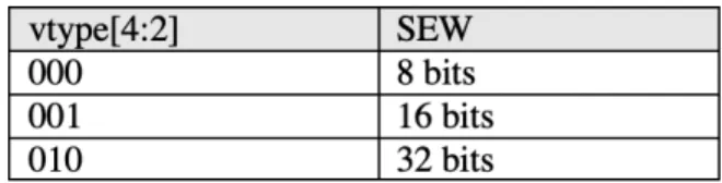
The ”RISC-V ’V’ Vector Extension” specification introduces vector terminology cru-cial to the understanding of this vector extension. Vector length (VL) refers to the number of elements which are stored in each vector. This value is stored in a control and status register (CSR). An element is a single value within a vector. Elements can have widths of 1 byte, 2 bytes, or 4 bytes. The term standard element width (SEW) refers to the current width of elements in a vector. SEW occupies bits [4:2] of the vtype CSR. SEW is encoded according to Table 2.1 below. [9]
Chapter 3
OTTER VECTOR EXTENSION IMPLEMENTATION
A diagram with the full implementation of the OTTER with vector extension is featured in Appendix B of this document.
3.1 Vector Configuration
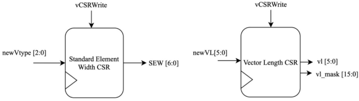
The vector length and standard element width (SEW) CSRs determine the operating status of the vector extension. These values can be updated using the vsetvl and vsetvli instructions. The length of a vector in elements is limited by the width of a vector register and the SEW. For example, if the vector width is 128 bits in the vector register file, and the SEW is 8 bits, the maximum vector length possible is 128/8, or 16, elements. The user can alter the width of the vectors in the vector register file to suit their application needs. Widths of the vector length CSR may need to be updated to support larger vector widths. Operating outside of these conditions will produce undefined errors. The vector length and SEW CSRs are shown in Figure 3.1 below.
3.2 Vector Register File
The vector register file (VRF) contains 32 vector elements of a user defined width. The least significant element, index zero, is stored at bits 0-(SEW-1). Elements are stored contiguously in a vector register from least significant to most significant. A vector in the VRF is written to element by element for memory operations. Otherwise, for vector algorithmic operations entire vectors are written at a time. An example layout for a vector with a length of 8 and a SEW of 16 stored in the vector register file is shown in Figure 3.2. below.
Figure 3.2: Vector layout in VRF
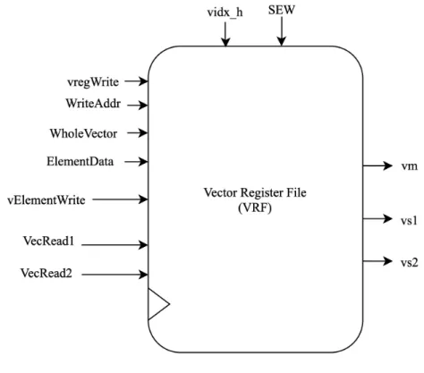
A black box diagram of the VRF is shown in Figure 3.3. The VRF performs syn-chronous vector-element and whole-vector writes. The element writes are controlled by the ”vElementWrite” signal, and the vector writes are controlled by the ”vreg-Write” signal. Data for the whole vector writes is supplied by the ”WholeVector” input. Likewise, ”ElementData” suppies a single element to write. The ”vidx h” input tells the VRF the highest bit which the single element is to be written to. Es-sentially which index inside the vector specified by ”WriteAddr” the element will be written to. The ”WriteAddr” input specifies which vector of the 32 available vectors will be overwritten. The VRF reads are asynchronous. The ”vm” output is always the vector mask at v0. The ”vs1” and ”vs2” outputs are the vectors specified by ”VecRead1” and ”VecRead2”, respectively.
3.2.1 Vector Masking
Some vector operations have a masked form. The vector mask is stored in vector register 0, v0. When masked operations are performed, the operation is only com-puted for the elements which the corresponding element in the vector mask has a value of 1, not 0. Elements for which the vector mask is 0 will retain the value of the source operand vs2 for VALU operations, if vs2 is specifiable. For the masked vmv instruction, all elements for which the vector mask is 0 will be 0 in the destination vector. The vector mask can be written using vector load instructions. A possible vector mask for a vector with a length of 8 and SEW of 2 bytes is shown in Figure 3.4:
3.3 Vector Loads and Stores
This implementation includes three types of vector loads and stores: unit-stride, strided, and indexed. Unit-stride loads and stores assume the vector elements are stored contiguously in memory as an array of SEW-width elements. Strided loads and stores assume the vector elements are stored contiguously in memory as an array of byte-stride-width elements. Indexed elements use another vector register as a list of byte-wise indexes into memory where each corresponding vector element is stored. A few different components were required to implement all three types of loads and stores with variable length and element-width vectors. These components consisted primarily encapsulated within the vector memory assist unit, described in the next section.
3.3.1 Vector Memory Assist
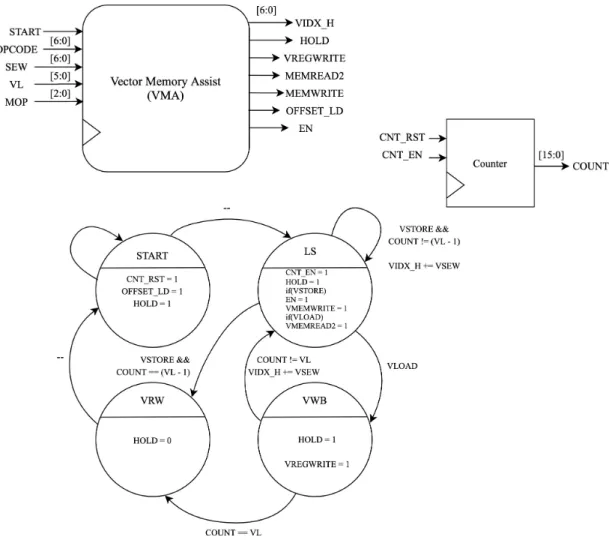
Figure 3.5: Vector Memory Assist Unit
progress. The hold signal is de-asserted in the last state to tell the control unit to move forward to the next instruction.
into memory. Another multiplexer chooses whether to pass the strided or indexed memory address to the memory module. Additionally, the ”VIDX H” signal is used to choose which vector index will be stored into memory or which vector index will be written to with a value loaded from memory. These components are shown in the RISC-V Vector Extension diagram.
Although this implementation requires at least a single clock cycle for each vector element, it is highly flexible for vectors of different lengths and SEWs. It interfaces directly with the existing OTTER memory module and control unit, and is fairly simplistic.
3.4 Vector Algorithmic Logic Unit
Chapter 4
RESULTS & ANALYSIS
To assess the performance of the OTTER Vector Extension, programs with identical behavior were written with and without the vector extension instructions. The non-vector programs were written using instructions from the RISC-V base 32-bit integer instruction set and run on the baseline multi-cycle OTTER. The timing results from running all programs were acquired using a Vivado simulation since access to FPGAs was limited.
The first assembly program compared adds the values of two arrays both 16 bytes in length, and stores the resulting values in a third array. Behavior is more accurately described by the snippet of C code below:
u i n t 8 t a [ 1 6 ] = {1 , 3 , 5 , 7 , 9 , 1 1 , 1 3 , 1 5 , 1 7 , 1 9 , 2 1 , 2 3 , 2 5 , 2 7 , 2 9 , 3 1};
u i n t 8 t b [ 1 6 ] = {2 , 4 , 6 , 8 , 1 0 , 1 2 , 1 4 , 1 6 , 1 8 , 2 0 , 2 2 , 2 4 , 2 6 , 2 8 , 3 0 , 3 2};
u i n t 8 t c [ 1 6 ] ;
f o r ( i n t i = 0 ; i < 1 6 , i ++) c [ i ] = a [ i ] + b [ i ] ;
. d a t a
v e c t o r 1 : . b y t e 1 , 3 , 5 , 7 , 9 , 1 1 , 1 3 , 1 5 , 1 7 , 1 9 , 2 1 , 2 3 , 2 5 , 2 7 , 2 9 , 3 1 v e c t o r 2 : . b y t e 2 , 4 , 6 , 8 , 1 0 , 1 2 , 1 4 , 1 6 , 1 8 , 2 0 , 2 2 , 2 4 , 2 6 , 2 8 , 3 0 , 3 2 v e c t o r 3 : . b y t e 0 , 0 , 0 , 0 , 0 , 0 , 0 , 0 , 0 , 0 , 0 , 0 , 0 , 0 , 0 , 0
. t e x t
. g l o b a l main
. t y p e main , @ f u n c t i o n main :
l a x5 , v e c t o r 1 l a x6 , v e c t o r 2 l a x7 , v e c t o r 3 l i x4 , 16
v s e t v l i x0 , x4 , e8 v l b . v v1 , ( x5 ) v l b . v v2 , ( x6 )
vadd . vv v3 , v1 , v2 vsb . v v3 , ( x7 ) j main
. d a t a
v e c t o r 1 : . b y t e 1 , 3 , 5 , 7 , 9 , 1 1 , 1 3 , 1 5 , 1 7 , 1 9 , 2 1 , 2 3 , 2 5 , 2 7 , 2 9 , 3 1 v e c t o r 2 : . b y t e 2 , 4 , 6 , 8 , 1 0 , 1 2 , 1 4 , 1 6 , 1 8 , 2 0 , 2 2 , 2 4 , 2 6 , 2 8 , 3 0 , 3 2 v e c t o r 3 : . b y t e 0 , 0 , 0 , 0 , 0 , 0 , 0 , 0 , 0 , 0 , 0 , 0 , 0 , 0 , 0 , 0
. t e x t
. g l o b a l main
. t y p e main , @ f u n c t i o n main :
l a x5 , v e c t o r 1 l a x6 , v e c t o r 2 l a x7 , v e c t o r 3 l i x1 , 16
l o o p :
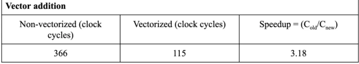
The total amount of clock cycles it took for the OTTER Vector Extension program to complete was 115. This includes initial setup of the stack pointer not shown in the code. The total amount of clock cycles it took for the non-vector version was 366. Results are summarized in Table 4.1. This includes the same initial setup sequence. The vectorized version produced a speedup by a factor of 3. One of the primary reasons for the large speedup is the addition operation in the vectorized version only takes 1 clock cycle to complete, whereas the addition in the non-vectorized version requires 16 separate cycles plus a fetch cycle for each. However, the speedup is much less significant for the loading and storing of the vectors. The vectorized version still requires at least 2 clock cycles for every element loaded from memory. In this case there are 16 elements, so at least 64 of the clock cycles are spent loading the vectors from memory, and another 16 are spent storing the resulting vector back to memory. However, there is still a slight speedup because the vector loads for each element occur back-to-back without the need for a fetch cycle in between.
Table 4.1: Array Addition Speedup Results
. d a t a
s o u r c e : . b y t e 1 , 3 , 5 , 7 , 9 , 1 1 , 1 3 , 1 5 , 1 7 , 1 9 , 2 1 , 2 3 , 2 5 , 2 7 , 2 9 , 3 1 , 2 , 4 , 6 , 8 , 1 0 , 1 2 , 1 4 , 1 6 , 1 8 , 2 0 , 2 2 , 2 4 , 2 6 , 2 8 , 3 0 , 3 2 d e s t : . b y t e 0 , 0 , 0 , 0 , 0 , 0 , 0 , 0 , 0 , 0 , 0 , 0 , 0 , 0 , 0 , 0 , 0 , 0 , 0 , 0 ,
0 , 0 , 0 , 0 , 0 , 0 , 0 , 0 , 0 , 0 , 0 , 0 . t e x t
. g l o b a l main
. t y p e main , @ f u n c t i o n main :
l a x5 , s o u r c e l a x6 , d e s t l i x4 , 32 l i x3 , 16
v s e t v l i x1 , x3 , e8 l o o p :
v l b . v v1 , ( x5 ) add x5 , x5 , x1 sub x4 , x4 , x1 vsb . v v1 , ( x6 ) add x6 , x6 , x1 bnez x4 , l o o p j main
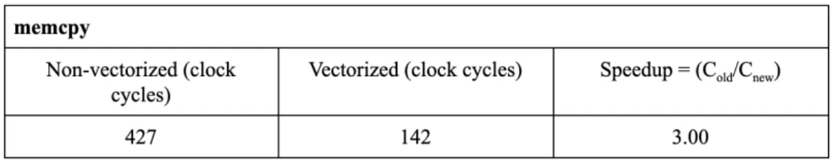
are summarized in Table 4.2.The reason for this is the vectors are able to complete 16 loads back-back without fetching another instruction. The same is true for the stores. Additionally, the vectorized loop runs twice, where the non-vectorized loop must run once for each byte. So, although the same amount of loads and stores are occurring, using vectors eliminates a lot of flow-control overhead.
. d a t a
s o u r c e : . b y t e 1 , 3 , 5 , 7 , 9 , 1 1 , 1 3 , 1 5 , 1 7 , 1 9 , 2 1 , 2 3 , 2 5 , 2 7 , 2 9 , 3 1 , 2 , 4 , 6 , 8 , 1 0 , 1 2 , 1 4 , 1 6 , 1 8 , 2 0 , 2 2 , 2 4 , 2 6 , 2 8 , 3 0 , 3 2 d e s t : . b y t e 0 , 0 , 0 , 0 , 0 , 0 , 0 , 0 , 0 , 0 , 0 , 0 , 0 , 0 , 0 , 0 , 0 , 0 ,
0 , 0 , 0 , 0 , 0 , 0 , 0 , 0 , 0 , 0 , 0 , 0 , 0 , 0 . t e x t
. g l o b a l main
. t y p e main , @ f u n c t i o n main :
l a x5 , s o u r c e l a x6 , d e s t l i x1 , 32 l o o p :
Table 4.2: memcpy Speedup Results
The examples shown in this section operated on single-byte elements, but can also be implemented using half-word and word size elements.
Chapter 5
FUTURE WORK
This implementation will hopefully act as a starting point for the OTTER vector extension, and other RISC-V projects. However, s number of improvements could be made in order to increase the functionality and efficiency of this version of the OTTER.
Although the VALU provides adequate performance increases, loading and storing vectors efficiently while maintaining the length and SEW flexibility is a problem yet to be solved. Memory bandwidth is often a limiting factor for vector processing. Possible improvements could include redesigning the memory module to allow for pipe-lined memory reads and writes. To overcome memory latency, many vector processors spread memory accesses across different memory banks[5]. Another design approach could allow entire vectors to be read or written to or from memory at once for unit-stride and unit-strided loads and stores, in order to achieve minimal cycle loads and stores. A major issue in vector supercomputers is providing such large bandwidth for memory accesses[5]. The memory module used in this implementation was designed specifically for the BASYS3 Artix-7 FPGA, but utilizing a different FPGA or external DRAM memory with caches would provide a more usable processor. DRAM is typically used for main memory because it is inexpensive [6].
re-errors. Most vector architectures contain multiple fully-pipelined functional units for increased performance [11, 6].
Also worthy of mentioning, this implementation was based off of the current version (0.7.x) of the ”RISC-V ’V’ Vector Extension” specification. The ’V’ extension has not yet been ratified and stabilized, so this implementation will need to be updated with each new release until the extension has been finalized.
Support does not yet exist for vectorization of C code into RISC-V instructions, but may become available in the near future with LLVM or gcc. Further research into this could make this extension more usable and appealing. The use of vectorization technology to translate code written in high-level languages to vector instructions may expand use cases for this extension [2].
BIBLIOGRAPHY
[1] Cal Poly Github. http://www.github.com/CalPoly.
[2] A. E. Eichenberger, P. Wu, and K. O’Brien. Vectorization for SIMD
Architectures with Alignment Constraints. SIGPLAN Not., 39(6):82–93, June 2004.
[3] A. K. Eman Aldakheel, Ganesh Chandrasekaran. Vector Processors, 2012. https://www.cs.uic.edu/~ajayk/c566/VectorProcessors.pdf.
[4] S. Greengard. Will RISC-V Revolutionize Computing? Communications of the ACM, 63(5):30–32, 2020.
https://cacm.acm.org/magazines/2020/5/244325-will-risc-v-revolutionize-computing/fulltext.
[5] J. L. Hennessy and D. A. Patterson. Innovation and intellectual property rights. In T. Green and N. McFadden, editors,Computer Architecture: A Quantitative Approach, pages G2–G34. Elsevier, Inc, 225 Wyman Street,
Waltham, MA 02451, USA, 2012.
[6] J. L. Hennessy and D. A. Patterson. Innovation and intellectual property rights. In T. Green and N. McFadden, editors,Computer Architecture: A Quantitative Approach, chapter 4, pages 261–342. Elsevier, Inc, 225 Wyman
Street, Waltham, MA 02451, USA, 2012.
[8] C. Kozyrakis and D. Patterson. Overcoming the Limitations of Conventional Vector Processors. 2003.
http://iram.cs.berkeley.edu/papers/code.kozyraki.isca.2003.pdf.
[9] RISC-V ”V” Vector Extension, 2019.
https://github.com/riscv/riscv-v-spec/releases/tag/0.7.1.
[10] Vectorization: SIMD Parallelism.
https://cvw.cac.cornell.edu/vector/overview_simd.
APPENDICES