Embedded C
Michael J. Pont
An imprint of
Pearson Education
PEARSON EDUCATION LIMITED
Head Office: London Office: Edinburgh Gate 128 Long Acre Harlow CM20 2JE London WC2E 9AN Tel: +44 (0)1279 623623 Tel: +44 (0)20 7447 2000 Fax: +44 (0)1279 431059 Fax: +44 (0)20 7240 5771 Websites: www.aw.com/cseng/
www.it-minds.com
First published in Great Britain in 2002 © Pearson Education Limited 2002
The right of Michael J. Pont to be identified as Author of this Work has been asserted by him in accordance with the Copyright, Designs and Patents Act 1988. ISBN 0 201 79523 X
British Library Cataloguing in Publication Data
A CIP catalogue record for this book can be obtained from the British Library Library of Congress-in-Publication Data
Pont, Michael J.
Embedded C/Michael J. Pont. p. cm.
Includes bibliographical references and index. ISBN 0-201-79523-X (pbx. : alk. paper)
1.C (Computer program language) 2. Embedded computer systems--Design and construction. I. Title.
QA76.73.C15 P65 2002 005.265--dc21
2001056731 All rights reserved; no part of this publication may be reproduced, stored
in a retrieval system, or transmitted in any form or by any means, electronic, mechanical, photocopying, recording, or otherwise without either the prior written permission of the Publishers or a licence permitting restricted copying in the United Kingdom issued by the Copyright Licensing Agency Ltd, 90 Tottenham Court Road, London W1P 0LP. This book may not be lent, resold, hired out or otherwise disposed of by way of trade in any form of binding or cover other than that in which it is published, without the prior consent of the Publishers.
The programs in this book have been included for their instructional value. The publisher does not offer any warranties or representations in respect of their fitness for a particular purpose, nor does the publisher accept any liability for any loss or damage arising from their use.
Many of the designations used by manufacturers and sellers to distinguish their products are claimed as trademarks. Pearson Education Limited has made every attempt to supply trademark information about manufacturers and their products mentioned in this book.
The publishers wish to thank Infineon Technologies for permission to reproduce the material in Figure 1.4.
10 9 8 7 6 5 4 3 2 1
Designed by Claire Brodmann Book Designs, Lichfield, Staffs Typeset by Pantek Arts Ltd, Maidstone, Kent
Michael J. Pontis an experienced software engineer who began his first embedded project in 1986. Since then he has lectured and carried out research at the University of Sheffield and the University of Leicester, and has provided consul-tancy and training services to a range of international companies. Michael is the author of two previous books Patterns for Time-Triggered Embedded Systemsand Software Engineering with C++ and CASE tools.
Preface
xi
1 Programming embedded systems in C
1
1.1 Introduction
1
1.2 What is an embedded system?
1
1.3 Which processor should you use?2
1.4 Which programming language should you
use? 7
1.5 Which operating system should you use?9
1.6 How do you develop embedded software?12
1.7 Conclusions15
2 Introducing the 8051 microcontroller family
17
2.1 Introduction
17
2.2 What’s in a name?17
2.3 The external interface of the Standard 8051
18
2.4 Reset requirements20
2.5 Clock frequency and performance
21
2.6 Memory issues23
2.7 I/O pins
29
2.8 Timers29
2.9 Interrupts30
2.10 Serial interface32
2.11 Power consumption32
2.12 Conclusions34
3 Hello, embedded world
35
3.1 Introduction
35
viii Contents
3.3 Configuring the simulator
37
3.4 Building the target39
3.5 Running the simulation39
3.6 Dissecting the program43
3.7 Aside: Building the hardware55
3.8 Conclusions56
4 Reading switches
57
4.1 Introduction
57
4.2 Basic techniques for reading from port pins
58
4.3 Example: Reading and writing bytes60
4.4 Example: Reading and writing bits (simple version)
61
4.5 Example: Reading and writing bits (generic version)62
4.6 The need for pull-up resistors67
4.7 Dealing with switch bounce
69
4.8 Example: Reading switch inputs (basic code)
70
4.9 Example: Counting goats75
4.10 Conclusions
80
5 Adding structure to your code
81
5.1 Introduction
81
5.2 Object-oriented programming with C
82
5.3 The Project Header (MAIN.H)88
5.4 The Port Header (PORT.H)
94
5.5 Example: Restructuring the ‘Hello Embedded World’ example
96
5.6 Example: Restructuring the goat-counting example103
5.7 Further examples
111
5.8 Conclusions111
6 Meeting real-time constraints
113
6.1 Introduction
113
6.4 Example: Creating a portable hardware delay
124
6.5 Why not use Timer 2?129
6.6 The need for ‘timeout’ mechanisms
129
6.7 Creating loop timeouts130
6.8 Example: Testing loop timeouts
133
6.9 Example: A more reliable switch interface
134
6.10 Creating hardware timeouts136
6.11 Example: Testing a hardware timeout
140
6.12 Conclusions142
7 Creating an embedded operating system
143
7.1 Introduction
143
7.2 The basis of a simple embedded OS
147
7.3 Introducing sEOS152
7.4 Using Timer 0 or Timer 1
161
7.5 Is this approach portable?166
7.6 Alternative system architectures166
7.7 Important design considerations when using sEOS
172
7.8 Example: Milk pasteurization174
7.9 Conclusions
187
8 Multi-state systems and function sequences
189
8.1 Introduction
189
8.2 Implementing a Multi-State (Timed) system
192
8.3 Example: Traffic light sequencing192
8.4 Example: Animatronic dinosaur
198
8.5 Implementing a Multi-State (Input/Timed) system
204
8.6 Example: Controller for a washing machine205
8.7 Conclusions215
9 Using the serial interface
217
9.1 Introduction
217
9.2 What is RS-232?217
9.4 The basic RS-232 protocol
218
9.5 Asynchronous data transmission and baud rates
219
9.6 Flow control220
9.7 The software architecture
220
9.8 Using the on-chip UART for RS-232 communications
222
9.9 Memory requirements224
9.10 Example: Displaying elapsed time on a PC
225
9.11 The Serial-Menu architecture237
9.12 Example: Data acquisition
237
9.13 Example: Remote-control robot252
9.14 Conclusions253
10 Case study: Intruder alarm system
255
10.1 Introduction
255
10.2 The software architecture
257
10.3 Key software components used in this example
257
10.4 Running the program258
10.5 The software
258
10.6 Conclusions283
11 Where do we go from here
285
11.1 Introduction
285
11.2 Have we achieved our aims?
285
11.3 Suggestions for further study286
11.4 Patterns for Time-Triggered Embedded Systems
288
11.5 Embedded Operating Systems288
11.6 Conclusions
289
Index
291
This book provides a ‘hardware-free’ introduction to embedded software for people who:
● Already know how to write software for ‘desktop’ computer systems.
● Are familiar with a C-based language (Java, C++ or C).
● Want to learn how C is used in practical embedded systems.
The remainder of this preface attempts to answer some questions which prospec-tive readers may have about the contents.
I What is an embedded system?
As far as this book is concerned:
This type of embedded system is all around us. Use of embedded processors in pas-senger cars, mobile phones, medical equipment, aerospace systems and defence systems is widespread, and even everyday domestic appliances such as dishwash-ers, televisions, washing machines and video recorders now include at least one such device.
II What type of processor is discussed?
This book focuses on the embedded systems based on the 8051 family of microcon-trollers. Prices for 8051 devices start at less than $1.00 (US). At this price, you get a performance of around 1 million instructions per second, and 256 bytes (not megabytes!) of on-chip RAM. The 8051’s profile (price, performance, available memory) matches the needs of many embedded systems very well. As a result, the
Preface
xii Preface
8051 architecture – originally developed by Intel – is now implemented in more than 400 chips; these are produced by a diverse range of companies including Philips, Infineon, Atmel and Dallas. Sales of this vast family are estimated to have the largest share (around 60%) of the microcontroller market as a whole, and to make up more than 50% of the 8-bit microcontroller market. Versions of the 8051 are currently used in a long list of embedded products, from automotive systems to children’s toys.
The low cost, huge range, easy availability and widespread use of the 8051 family makes it an excellent platform for developing embedded systems: these same factors also make it an ideal platform for learningabout embedded systems. Whether you will subsequently use 8-, 16- or 32-bit embedded processors, learning to work within the performance and memory limits of devices such as the 8051 is a crucial requirement in the cost-conscious embedded market. You simply cannot acquire these skills by developing code for a Pentium (or similar) processor.
III Which operating system is used?
The 256 bytes of memory in the 8051 are – of course – insufficient to support any ver-sion of Windows, Linux or similar desktop operating systems. Instead, we will describe how to create your own simple ‘embedded operating system’ (see Chapter 7). This ‘do-it-yourself’ approach is typical in small embedded applications, where the memory requirements and expense of a desktop operating system (like Windows or Linux) or of a so-called ‘real-time operating system’ simply cannot be justified. However, the approach is also in widespread use in large embedded systems (for example, aerospace applications or X-by-wire systems in the automotive industry), where conventional operating systems are generally considered to be too unpredictable.
Learning to work on a ‘naked’ processor and create your own operating system are key requirements for software developers wishing to work with embedded systems.
IV What type of system is discussed?
This book presents a number of examples adapted from working embedded sys-tems. These include:
● A remotely-controlled robot.
● A traffic-light sequencer.
● A system for monitoring liquid flow rates.
● An animatronic dinosaur.
● A general-purpose data acquisition system.
These and other examples are used to illustrate key software architectures that are in widespread use in embedded designs; the examples may be adapted and extended to match the needs of your own applications.
The book concludes with a final case study: this brings together all of the fea-tures discussed in earlier chapters in order to create an intruder alarm system. This case study includes the following key components:
● A suitable embedded operating system.
● A multi-state system framework.
● Software to process the inputs from door and window sensors.
● A simple ‘keypad’ library to process passwords entered by the user.
● Software to control external port pins (to activate the external bell).
● An ‘RS-232’ library to assist with debugging.
V Do I need a degree in electronics in order to use this book?
Please consider the following statement:
This is a concern which is commonly expressed by desktop programmers who – if they ever learned anything about electronics at school, college or university – have probably forgotten it.
If you don’t know the difference between a MOSFET and a BJT, or even the dif-ference between a resistor and a capacitor, please relax. You don’t need to have any knowledge of electronics in order to make full use of this book. Neither will you need a soldering iron, breadboard or any electronic components. In short, this book is (99%) hardware free.
To write software for the 8051 devices considered in this book, we will use an industry-standard (Keil) compiler. To test this software, we will use a hardware simulator. Copies of both compiler tools and the simulator are included on the enclosed CD. Using these tools, all of the examples in the book may be run, mod-ified and recompiled and tested, using a standard Windows PC.
This approach allows experienced desktop programmers to quickly understand the key features of embedded systems before they need to ‘get their hands dirty’ and build some hardware.
VI What’s on the CD?
In addition to the Keil compiler and hardware simulator (discussed in the previous section), the CD also includes source code files for all the examples and the case study: this code is in the ‘C’ programming language and is compatible with the Keil compiler.
The CD also contains useful information about the 8051 microcontroller family, including a large number of relevant data sheets and application notes.
VII What’s the link between this book and your other 8051 book
(
Patterns for Time-Triggered Embedded Systems
)?
Embedded Cprovides an introduction to the use of C in embedded projects. If you want to learn more about embedded systems after you finish this book, then Patterns for Time-Triggered Embedded Systems(PTTES) may be of interest.1
PTTES is a large (1000-page) book which includes a comprehensive set of ‘design patterns’ to support the development of embedded systems based on the 8051 family of microcontrollers. In total, details of more than 70 useful patterns are provided, complete with guidelines to help you apply these techniques in your own projects: full source code for all of the patterns is included on the PTTES CD.
The book includes: patterns for embedded operating systems (for both single-processor and multi-single-processor applications); patterns for user-interface designs using switches, keypads, LED and liquid crystal displays; patterns for PID control; patterns for PWM; patterns for analogue-to-digital and digital-to-analogue conver-sion; patterns for RS-232, RS-485, CAN, SPI and I2C serial networks; hardware patterns describing reset, oscillator and memory circuits.
VIII Is the code ‘free ware’?
The code included in this book took many years to produce. It is not ‘free ware’, and is subject to some simple copyright restrictions. These are as follows:
● If you have purchased a copy of this book, you are entitled to use the code listed in the text (and included on the CD) in your projects, should you choose to do so. If you use the code in this way, then no run-time royalties are due. xiv Preface
● If you are using the code in a company, and (for example) ten people are using the code, the company should own ten copies of this book.
● If you are teaching in a university or college, you may freely distribute this code to your students without requiring a licence, as long as the code is used for teaching purposes and no commercial application is involved. Please note that teaching (by university or college staff, or anyone else) of ‘short courses’ for industry or for purposes of ‘continuing professional development’ does notfall into this category: if in doubt, please contact me for clarification.2
● You may not, under any circumstances, publish any of the source code included in the book or on the CD, in any form or by any means, without explicit written authorization from me. If you wish to publish limited code frag-ments then, in most circumstances, I will grant this permission, subject only to an appropriate acknowledgment accompanying the published material. If you wish to publish more substantial code listings, then payment of a fee may be required. Please contact me for further details.
IX How should this book be read?
This short book is intended to be read from cover to cover.
Access to a Windows PC while reading will be useful in later chapters, as this will allow you to try out the examples for yourself: however, this is not essential.
X What about bug reports and code updates?
There is fair amount of code involved in this project, both in the book itself and on the associated CD. I have personally tested all of the code that appears here. Nonetheless, errors can creep in.
If you think you have found a bug, please send me an e-mail (the address is at the end of this preface), and I will do my best to help.
XI What about other reader comments?
I began my first embedded project in 1986. When writing Embedded C, I wanted to, try and provide the kind of information that I needed (but could not find) at that time.
I would appreciate your comments and feedback. For example, should the book be longer? Shorter? What other areas should I cover? What should I miss out? Would you like to see a future edition focusing on a different family of microcon-trollers? If so, which one?
To ensure that any future editions continue to provide the information you need, I would be delighted to hear of your experiences (good or bad) using the book.
XII Credit where credit is due
The publication of this book would not have been possible without the help and support of a number of people.
In particular, I would like to thank:
● The ‘Electronic and Software Engineering’ students at the University of Leicester who have provided useful feedback on this material as they attended my introductory courses in embedded systems in recent years.
● Simon Plumtree at Pearson Education, who responded positively to my sugges-tion that this material was suitable for wider publicasugges-tion.
● Karen Sellwood at Pearson, who helped to keep the project on the rails.
● Reinhard Keil and his colleagues, for reviewing the first draft of this book and – again – providing the core of the CD.
● Jim Cooling, for his review of the first draft of this book.
● Chris Stephens, for his review of the first draft of this book.
● Penelope Allport for managing the project.
● Sara Barnes for copy editing; Claire Brodmann for the design; Barbara Archer for proof reading and David Worthington for the index.
● Barbara and Gordon Pont for proof reading.
● Sarah, for convincing me that ‘No More Shall We Part’ was worth listening to again.
1.1 Introduction
This is a short book for people who already know how to program desktop computers and now wish to develop software for embedded systems.
In this introductory chapter, we consider some important decisions that must be made at the start of any embedded project:
● The choice of processor.
● The choice of programming language.
● The choice of operating system.
We begin by considering the meaning of the phrase ‘embedded system’.
1.2 What is an embedded system?
When we talk about ‘embedded systems’, what do we mean? Opinions vary. Throughout this book, we will use the following loose definition:
1
chapter
1
Programming embedded
systems in C
Typical examples of embedded applications that are constructed using the tech-niques discussed in this book include:
● Mobile phone systems(including both customer handsets and base stations).
● Automotive applications(including braking systems, traction control, airbag release systems, engine-management units, steer-by-wire systems and cruise-control applications).
● Domestic appliances(including dishwashers, televisions, washing machines, microwave ovens, video recorders, security systems, garage door controllers).
● Aerospace applications(including flight control systems, engine controllers, autopilots and passenger in-flight entertainment systems).
● Medical equipment(including anaesthesia monitoring systems, ECG moni-tors, drug delivery systems and MRI scanners).
● Defence systems(including radar systems, fighter aircraft flight control sys-tems, radio systems and missile guidance systems).
Please note that our definition of embedded systems excludesapplications such as ‘personal digital assistants’ (PDAs) running versions of Windows or similar operating systems: from a developer’s perspective, these are best viewed as a cut-down version of a desktop computer system. This type of application makes up a very small per-centage of the overall ‘embedded’ market and is not considered in this book.
1.3 Which processor should you use?
When desktop developers first think about working with embedded systems, there is a natural inclination to stick with what they know and look for a book which uses Pentium processors or other devices from this family (such as the 80486, or the Intel 188). However, if you open up the engine management unit or the airbag release system in your car, or take the back off your dishwasher, you will not find any of these processors sitting inside, nor will there be anywhere to plug in a key-board, graphics display or mouse.
would buy a portable music player that requires ten large batteries to run, and needs a trolley to transport it?)
Overall, the state-of-the art technology used in desktop processors matches the needs of the PC user very well: however, their key features – an ability to execute industry-standard code at a rate of more than 1000 million instructions per second – come with a heavy price tag and are simply not required in most embedded systems. The 8051 device is very different. It is a well-tested design, introduced in its original form by Intel in 1980 (Figure 1.1). The development costs of this device have now been fully recovered, and prices of modern 8051 devices now start at less than US $1.00. At this price, you get a performance of around 1 million instructions per second, and 256 bytes(not megabytes!) of on-chip RAM. You also get 32 port pins and a serial interface. The 8051’s profile (price, performance, available memory, serial interface) match the needs of many embedded systems very well. As a result, it is now produced in more than 400 different forms by a diverse range of companies including Philips, Infineon, Atmel and Dallas. Sales of this vast family are estimated to have the largest share (around 60%) of the micro-controller market as a whole, and to make up more than 50% of the 8-bit microcontroller market. Versions of the 8051 are currently used in a long list of embedded products, from children’s toys to automotive systems.
Building a desktop PC from an 8051 would not be a practical proposition, but it is an excellent device for building many embedded systems. One important factor is that the 8051 requires a minimum number of external components in order to operate. For example, Figure 1.2 shows the circuit diagram for a complete 8051-based application.
FIGURE 1.1 The external interface of a ‘Standard’ ‘8051’ microcontroller (40-pin DIP package). Standard 8051s have four ports, and are pin compatible with the original 8051/8052 from Intel. Further information about the pin functions is given in Chapter 2
The different nature of the embedded and desktop markets is emphasized by the fact that some of the more recent 8051 devices – far from being more powerful and having more features than the 1980 original – actually have fewerfeatures. For example, as we will discuss in Chapter 2, the original 8051 (Figure 1.1) had 32 I/O pins and could – if necessary – be connected to up to 128 kbytes of external memory. By contrast, the more recent ‘Small 8051’ devices typically have only some 15 I/O pins, and do not support external memory. These devices are finding their way into applications that would have involved a small number of discrete components (transistors, diodes, resistors, capacitors) a few years ago, but which may now be implemented more cheaply using microcontrollers (Figure 1.3). 4 Embedded C
FIGURE 1.2 An example of an 8051 microcontroller in use. In this example, the microcontroller is intended to flash an LED connected to Pin 6. In addition to this LED, only a simple ‘reset’ circuit is required (the capacitor and resistor connected to Pin 9), plus an external oscillator (in this case, a 3-pin ceramic resonator). We will consider some software that could be used to control such an application in Chapter 3
‘8051’
1 2 3 4 5 6 7 8 9 10 11 12 13 14 15 16 17 18 19 20 40 39 38 37 36 35 34 33 32 31 30 29 28 27 26 25 24 23 22 21 VCC P0.0 P0.1 P0.2 P0.3 P0.4 P0.5 P0.6 P0.7 / EA ALE / PSEN P2.7 P2.6 P2.5 P2.4 P2.3 P2.2 P2.1 P2.0 P1.0 P1.1 P1.2 P1.3 P1.4 P1.5 P1.6 P1.7 RST P3.0 P3.1 P3.2 P3.3 P3.4 P3.5 P3.6 P3.7 XTL2 XTL1 VSS 5V10 µF
Both the Standard and Small 8051s are aimed, largely, at low-performance applica-tion areas, where limited memory is required, and one of the most important considerations is product cost. This forms a large segment of the embedded market but – of course – not all projects take this form. To develop applications requiring additional hardware or larger amounts of memory, we can opt to switch to a 16-bit (or 32-bit) microcontroller environment – or even consider using a desktop micro-processor. However, such a move can require a major investment in staff, training and development tools. An alternative is to use one of the Extended 8051 devices introduced in recent years by a range of manufacturers (see Figure 1.4).
One important application area for Extended 8051s has been the automotive sector. Recent economic, legislative and technological developments in this sector mean that an increasing number of road vehicles contain embedded systems. Linking these systems together in many recent vehicles is a low-cost, two-wire Controller Area Network (CAN) computer bus. The CAN bus eliminates the expen-sive (and heavy) multi-wire looms, shaving around US $600 or more from production costs: a significant saving.
FIGURE 1.3 An example of a ‘Small 8051’ in use. Small 8051s are produced by Atmel and Philips. They have two ports (or less), and around 20 pins. In this case, an Atmel AT89C2051 is used, in a ‘cupboard light’ application. The circuit here is intended for use in a cupboard (closet), and will be battery powered. When the light is switched on (by pressing the switch), it will operate for 20 seconds. If, in this time, the user does not press the switch again (to turn off the light), the power will be removed automatically. This is a typical example of a very simple product that may now be economically produced using a microcontroller
Atmel 2051
1 2 3 4 5 6 7 8 9 10 20 19 18 17 16 15 14 13 12 11 VCC P1.7 P1.6 P1.5 P1.4 P1.3 P1.2 P1.1 P1.0 P3.7 RST P3.0 P3.1 XTL2 XTL1 P3.2 P3.3 P3.4 P3.5 GND 10 KΩ4V - 6V (battery)
10 µF
5.5V, 0.3A lamp
E B
This is not quite the end of the story. In order to connect to the CAN bus, the var-ious devices – from door mirrors to braking systems – each require an embedded processor. As a consequence, a modern passenger car may typically have 50 processors on board. To use 50 desktop chips in these circumstances, we would need to spend around US $5000. This cost greatly outweighs any saving achieved through the use of the CAN bus in the first place: in addition, the desktop proces-sor would not have on-chip support for CAN, so additional hardware would be needed in order to provide this, further increasing our costs and design complex-ity. As an alternative, various Extended 8051s have on-chip hardware support for 6 Embedded C
FIGURE 1.4 An example of an Extended 8051 device. Extended 8051s have additional on-chip facilities, and additional port pins. In the case of the Infineon C515C (shown here), the additional facilities include support for the ‘Controller Area Network’ (CAN) bus: this bus is widely used in the automotive sector and in industrial environments. Figure reproduced with permission from Infineon
40 P5.6 39 P5.5 38 P5.4 37 P5.3 36 P5.2 35 P5.1 34 P5.0 33 VCCE2 32 HWPD 31 VSSC1 30 N.C. 29 P4.0 ADST
28 P4.1 SCLK
27 P4.0/SRI 26 PE/SWD 25 P4.3/STO 24 P44.4 SLS
23 P4.5 INTB
22 P4.6 TXDC
21 P4.7 RXDC
20 RESET 19 N.C. 18 VAREF 17 VAGDN 16 P6.7/AIN7 15 P6.6/AIN6 14 P6.5/AIN5 13 P6.4/AIN4 12 P6.3/AIN3 11 P6.2/AIN2 10 P6.1/AIN1 9 P6.0/AIN0 8 VSSCLK 7 VCCCLK 6 P3.0/RXD 5 P3.1/TXD 4
P3.2 INT0
3
P3.3 INT1
2 P3.4/T0 1 P3.5/T1 61 62 63 64 65 66 67 68 69 70 71 72 73 74 75 76 77 78 79 80 41 42 43 44 45 46 47 48 49 50 51 52 53 54 55 56 57 58 59 60
P5.7 P0.7/AD7 P0.6/AD6 P0.5/AD5 P0.4/AD4 P0.3/AD3 P0.2/AD2 P0.1/AD1 P0.0/AD0 VSSEXT VCCEXT EA ALE PSEN CPUR P2.7/A15 P2.6/A14 P2.5/A13 P2.4/A12 P2.3/A11
P2.2/A10 P2.1/A9 P2.0/A8 XTAL1 XTAL2 VSSE1 VSS1 VCC1 VCCE1
P1.0 INT3/CC0 P1.1 INT4/CC1 P1.2 INT5/CC2 P1.3 INT6/CC3 P1.4 INT2 P1.5 T2LX P1.6 CLKOUT P1.7/T2 P7.0 INT7 P3.7 RD P3.6 WR C515C
P-MQFP-80 Package
CAN (see Figure 1.4). The use of 50 such chips in a car design would not generally cost more than US $200. Using these processors, the switch to CAN may result in overall savings of around US $400 per vehicle.
The final thing to note about the 8051 architecture is that, if none of the 400 or so existing chips matches the needs of your application, you can now build your own device. For example, the Triscend3E5 series of devices have 8051 cores, plus
an additional area of field-programmable gate arrays (FPGAs) with which you can create your own ‘on chip’ hardware. Alternatively, for even greater flexibility, Xilinx Foundation4provides a comprehensive set of tools for the programming of
‘blank’ FPGAs or Application-Specific ICs (ASICs). Compatible with these tools are a small range of 8051 ‘cores’ which can be purchased – for example – from Dolphin Integration.5The use of such techniques allows you to create your own
completely customized 8051 microcontroller, in order to match precisely your par-ticular requirements.
Overall, the low cost, huge range, easy availability and widespread use of the 8051 architecture makes it an excellent platform for developing embedded sys-tems: these same factors also make it an ideal platform for learning about embedded systems. Whether you will subsequently use 8-, 16- or 32-bit embedded processors, learning to work within the performance and memory limits of devices such as the 8051 is a crucial requirement in the cost-conscious embedded market. You simply cannot acquire these skills by developing code for a Pentium (or simi-lar desktop) processor.
1.4 Which programming language should you use?
Having decided to use an 8051 processor as the basis of your embedded system, the next key decision that needs to be made is the choice of programming lan-guage. In order to identify a suitable language for embedded systems, we might begin by making the following observations:
● Computers (such as microcontroller, microprocessor or DSP chips) only accept instructions in ‘machine code’ (‘object code’). Machine code is, by definition, in the language of the computer, rather than that of the programmer. Interpretation of the code by the programmer is difficult and error prone.
● All software, whether in assembly, C, C++, Java or Ada must ultimately be trans-lated into machine code in order to be executed by the computer.
● There is no point in creating ‘perfect’ source code, if we then make use of a poor translator program (such as an assembler or compiler) and thereby generate executable code that does not operate as we intended.
● Embedded processors – like the 8051 – have limited processor power and very limited memory available: the language used must be efficient.
● To program embedded systems, we need low-level access to the hardware: this means, at least, being able to read from and write to particular memory loca-tions (using ‘pointers’ or an equivalent mechanism).
Of course, not all of the issues involved in language selection are purely technical:
● No software company remains in business for very long if it generates new code, from scratch, for every project. The language used must support the creation of flexible libraries, making it easy to re-use (well-tested) code components in a range of projects. It must also be possible to adapt complete code systems to work with a new or updated processor with minimal difficulty.
● Staff members change and existing personnel have limited memory spans. At the same time, systems evolve and processors are updated. As concern over the ‘Year 2000’ problem in recent years has illustrated, many embedded systems have a long lifespan. During this time, their code will often have to be main-tained. Good code must therefore be easy to understand now, and in five years’ time (and not just by those who first wrote it).
● The language chosen should be in common use. This will ensure that you can continue to recruit experienced developers who have knowledge of the lan-guage. It will also mean that your existing developers will have access to sources of information (such as books, training courses, WWW sites) which give exam-ples of good design and programming practice.
Even this short list immediately raises the paradox of programming language selection. From one point of view, only machine code is safe, since every other language involves a translator, and any code you create is only as safe as the code written by the manufacturers of the translator. On the other hand, real code needs to be maintained and re-used in new projects, possibly on different hardware: few people would argue that machine code is easy to understand, debug or to port.
Inevitably, therefore, we need to make compromises; there is no perfect solu-tion. All we can really say is that we require a language that is efficient, high-level, gives low-level access to hardware, and is well defined. In addition – of course – the language must be available for the platforms we wish to use. Against all of these points, C scores well.
● It is ‘mid-level’, with ‘high-level’ features (such as support for functions and modules), and ‘low-level’ features (such as good access to hardware via pointers).
● It is very efficient.
● It is popular and well understood.
● Even desktop developers who have used only Java or C++ can soon understand C syntax.
● Good, well-proven compilers are available for every embedded processor (8-bit to 32-bit or more).
● Experienced staff are available.
● Books, training courses, code samples and WWW sites discussing the use of the language are all widely available.
Overall, C’s strengths for embedded system development greatly outweigh its weaknesses. It may not be an ideal language for developing embedded systems, but it is unlikely that a ‘perfect’ language will ever be created.
1.5 Which operating system should you use?
Having opted to create our 8051-based applications using C, we can now begin to consider how this language can be used. In doing so, we will begin to probe some of the differences between software development for desktop and embedded systems.
In the desktop environment, the program the user requires (such as a word processor program) is usually loaded from disk on demand, along with any required data (such as a word processor file). Figure 1.5 shows a typical operating environment for such a word processor. Here the system is well insulated from the underlying hardware. For example, when the user wishes to save his or her latest novel on disk, the word processor delegates most of the necessary work to the operating system, which in turn may delegate many of the hardware-specific com-mands to the BIOS (basic input/output system).
There are two fundamental differences between the embedded systems we are con-cerned with in this book and desktop computer systems:
1 The vast majority of embedded systems are required to run only one program: this program will start running when the microcontroller is powered up, and will stop running when the power is removed.
2 Many of the facilities provided by the modern desktop OS – such as the ability to display high-resolution graphics, printing facilities and efficient disk access – are of little value in embedded systems, where sophisticated graphics screens, printers and disks are generally unavailable.
As a consequence, the simplest architecture in an embedded system is typically a form of ‘Super Loop’ (see Listing 1.1).
Listing 1.1
Part of a simple Super Loop demonstration
void main(void) {
// Prepare run function X X_Init();
while(1) // ‘for ever’ (Super Loop) {
X(); // Run function X() }
}
10 Embedded C
FIGURE 1.5 A schematic representation of the BIOS/OS sandwich from a desk-bound computer system running some word processor software
Word Processor
Operating System
BIOS
Hardware
OS provides ‘common code’ for: • Graphics
It is important to appreciate that there is no operating system in use here. When power is applied to the system, the function main()will be called: having per-formed the initializations, the function X()will be called, repeatedly, until the system is disconnected from the power supply (or a serious error occurs).
For example, suppose we wish to develop a microcontroller-based control system to be used as part of the central-heating system in a building. The simplest version of this system might consist of a gas-fired boiler (which we wish to con-trol), a sensor (measuring room temperature), a temperature dial (through which the desired temperature is specified) and the controller itself (Figure 1.6).
We assume that the boiler, temperature sensor and temperature dial are connected to the system via appropriate ports.
Here, precise timing is not required, and a Super Loop framework similar to that shown in Listing 1.2 may be appropriate.
Listing 1.2
Part of the code for a simple central-heating system
/*---*-Main.C
---Framework for a central heating system using a Super Loop. [Compiles and runs but does nothing useful]
-*---*/ #include "Cen_Heat.h"
/*---*/ void main(void)
{
// Init the system C_HEAT_Init();
FIGURE 1.6 An overview of a central heating controller Central heating controller
Boiler Temperature
sensor
while(1) // 'for ever' (Super Loop) {
// Find out what temperature the user requires // (via the user interface)
C_HEAT_Get_Required_Temperature();
// Find out what the current room temperature is // (via temperature sensor)
C_HEAT_Get_Actual_Temperature();
// Adjust the gas burner, as required C_HEAT_Control_Boiler();
} }
/*---*--- END OF FILE /*---*---/*---*---/*---*---/*---*---/*---*---/*---*---/*---*---/*---*---/*---*---/*---*---/*---*--- ---*---*/
It should be noted that the Super Loop architecture employed in this central-heating system is not appropriate for all embedded applications. For more advanced applications, we will describe how to create your own embedded operat-ing system in Chapter 7.
1.6 How do you develop embedded software?
The process of compiling, linking and executing the program shown (in part) in Listing 1.2 on a desktop PC is straightforward. In this environment, the executable code we create will, in almost all cases, be intended to run on a desktop computer similar to the one on which the code development is carried out. In the embedded environment this is rarely the case. For example, the 8051 devices we will use throughout this book do not have sufficient memory resources to allow them to be used for compiling programs, and they will not support a keyboard or graphics display. As a result, the code will be ‘cross-compiled’ on a desktop PC, generating machine code that is compatible with the 8051 family: this process will be exam-ined in greater detail in Chapter 3.
Having created the required executable code, we need to test it and refine it. To do this, we need to do the following:
1 Build the hardware for the embedded system.
For programmers without experience of electronics, the process of building embedded hardware is a daunting one. A typical approach used to prototype small embedded applications is the ‘breadboard’. This allows the microcontroller and associated components to be connected together, without soldering, in order to test and refine the hardware and software design.
For example, consider the breadboard shown in Figure 1.7. This code is for a simple alarm clock with an LED display and some switches to adjust the time and alarm settings. As the photograph makes clear, even in this simple application there are many opportunities for wiring errors. As a result – if the system does not operate correctly – it may not be clear whether this is as a result of software errors or hardware problems.
A means of transferring the program code to the microcontroller is also required. In examples such as the alarm clock shown in Figure 1.7, the microcon-troller used will typically incorporate some form of ‘flash’ memory to store the program code.6To transfer the executable code to the microcontroller, we will use
a ‘flash’ programmer. Flexible programmers (for use with the whole family of 8051 processors, and other devices) may cost several hundred dollars. Alternatively, ‘hobby’ developers often choose to save money by developing their own program-mer at home: however, to do this, experience of electronics construction techniques is required.
Overall, the process of wiring up a breadboard to test your first simple embedded programs can be daunting, expensive and rather prone to error. Fortunately, there is now an alternative approach that can be used by those starting out in this area:
6. We will consider the different types of available memory in greater detail in Chapter 2.
1 Create the executable code for the embedded system on a desktop PC using an appropriate cross-compiler and related tools (as above).
2 Use a software simulator(running on the desktop PC) to test the code.
3 Repeat Step 1 and Step 2, as necessary, until the software operates as required.
Throughout this book we will use such a simulator, produced by Keil Software. This provides you with a very flexible ‘hardware’ platform, on which you can gain expe-rience of embedded software without simultaneously having to learn how to solder. A copy of this simulator is included on the enclosed CD. Please note that this is an evaluation version of the simulator and has some restrictions compared with the full version: nonetheless, it can be used to run all of the examples in this book. We describe how to use this simulator in Chapter 3.
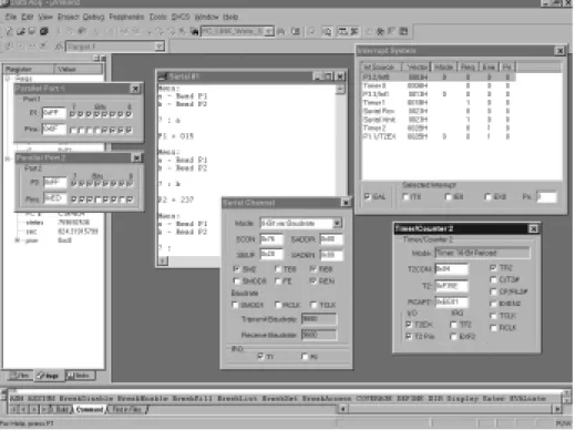
An example of the simulator in use is given in Figure 1.8. As we will see in sub-sequent chapters, this simulator accurately reproduces the activity of all key components in various members of the 8051 family.
14 Embedded C
Please note that these simulators are not simply ‘toys’ to be used only when learn-ing how to develop embedded software. Even where hardware will be constructed, most developers will conduct early software tests on a simulator before using the hardware. This can greatly speed up the development process. For example, in applications using a serial interface (see Chapter 9), the simulator can determine the precise baud rate being generated by your software: this can avoid many sub-sequent problems. In addition, the simulator provides key facilities for debugging, such as support for ‘profiling’ the code, a process that will typically involve meas-uring the duration of particular functions. As we will see in subsequent chapters, timing plays a central role in most embedded applications, and the ability to measure function durations in a straightforward way makes the simulator a key debugging tool.
1.7 Conclusions
In this introductory chapter, we have considered:
● The type of embedded systems that will be discussed in this book.
● The choice of programming language for embedded systems.
● The choice of operating system for embedded systems.
● The process of creating executable code for an embedded processor on a desktop PC.
● The process of testing the embedded code.
2.1 Introduction
In Chapter 1, we looked at some of the key features of ‘embedded’ software. In the remainder of the book, our focus will be on 8051-based embedded systems.
In this chapter, we consider some of the key features of the 8051 family.
2.2 What’s in a name?
Before we look in more detail at the features of the various 8051 devices, we should note that the names given to the various family members is always a source of confusion to new developers. For example, the 8031, 8751, 8052, 8032, C505C, C515C, C509, C868, 80C517, 83C452, 80C390, ADµC812 and MAX7651 are all members of the 8051 family. The names of the devices provide little or no indication of the family connections.
Particular confusion arises over the labels ‘8051’ and ‘8052’. The 8052 was launched (by Intel) shortly after the 8051 appeared. The architecture was the same, except that the 8052 had more on-chip RAM (256 bytes cf. 128 bytes), and also had an additional timer (Timer 2).
You should be aware that, despite the fact that they are described as ‘8051s’, almost all current devices are based on the slightly later 8052 architecture. As the distinction between ‘8051’ and ‘8052’ is now purely of historical interest, we will follow this convention and use the label ‘8051’ throughout this book.
If you want more information about the various 8051 devices that are available, you will find a large number of relevant data sheets on the CD. In addition, Keil
17
chapter
2
Software have a WWW site7with details of current 8051 variants (more than 400
devices are listed at the time of writing). This site is regularly updated. Another useful source of information about the different members of the 8051 family is the ‘Micro Search’ facility provided by Computer Solutions.8
2.3 The external interface of the Standard 8051
As we saw in Chapter 1, the 400 different devices in the 8051 family can be divided into three main groups: the Standard 8051s, the Small 8051s and the Extended 8051s (Figure 2.1).
We will assume the use of Standard 8051 devices throughout this book. As the architecture of the Small and Extended 8051s is derived from that of the Standard 8051, the techniques we discuss may be applied with any 8051-based device, and the C compiler used throughout this book (and introduced in Chapter 3) can be used to develop code for all 8051 derivatives.
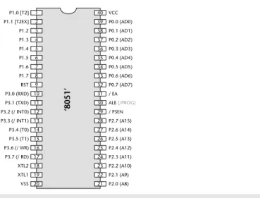
Figure 2.2 shows the external interface of the Standard 8051, and briefly sum-marizes the function of each of the port pins. Note that, in many cases, the port pins can serve more than one purpose.
18 Embedded C
7. www.keil.com 8. www.computer-solutions.co.uk
FIGURE 2.1 The relationship between the various ‘clans’ in the 8051 family. The Standard 8051s are modern implementations of the original 8051 / 8052 device. Both the Small 8051s and the Extended 8051s are derived from (and share key architectural features with) the Standard 8051s. From the developer’s perspective, a key feature of this family is that a single
compiler is required in order to generate code for all current devices Standard 8051
Small 8051 Extended 8051
Extended 8051
Members of the 8051 family with extended range of no-chip facilities (e.g. CAN controllers, ADC, DAC, etc), large numbers of port pins, and in recent devices -support for large amounts of off-chip memory. Typical applications: Industrial and automotive systems Small 8051 Low-cost members of the 8051 family with reduced number of port pins, and no support for off-chip memory.
Typical application:
‘8051’ 1 2 3 4 5 6 7 8 9 10 11 12 13 14 15 16 17 18 19 20 40 39 38 37 36 35 34 33 32 31 30 29 28 27 26 25 24 23 22 21 VCC P0.0 (AD0) P0.1 (AD1) P0.2 (AD2) P0.3 (AD3) P0.4 (AD4) P0.5 (AD5) P0.6 (AD6) P0.7 (AD7) / EA ALE (/PROG)
/ PSEN P2.7 (A15) P2.6 (A14) P2.5 (A13) P2.4 (A12) P2.3 (A11) P2.2 (A10) P2.1 (A9) P2.0 (A8) P1.0 [T2] P1.1 [T2EX] P1.2 P1.3 P1.4 P1.5 P1.6 P1.7 RST P3.0 (RXD) P3.1 (TXD) P3.2 (/ INT0) P3.3 (/ INT1) P3.4 (T0) P3.5 (T1) P3.6 (/ WR) P3.7 (/ RD) XTL2 XTL1 VSS
Pin(s) Function
1–8 Port 1. The bi-directional pins on this port may be used for input and output: each pin may be individually controlled and – for example – some may be used for input while others on the same port are used for output. Use of these pins is discussed in detail in Chapter 3 and Chapter 4. In 8052-based designs, Pin 1 and Pin 2 have alternative functions associated with Timer 2 (see Section 2.8).
9 The ‘Reset’ pin. When this pin is held at Logic 0, the chip will run normally. If, while the oscillator is running, this pin is held at Logic 1 for two (or more) machine cycles, the microcontroller will be reset. An example of simple reset hardware is given in Section 2.4. 10–17 Port 3. Another bi-directional input port (same operation as Port 1).
Each pin on this port also serves an additional function.
Pin 10 and Pin 11 are used to receive and transmit (respectively) serial data using the ‘RS-232’ protocol. See Chapter 9 for details.
Pin 12 and Pin 13 are used to process interrupt inputs. We say more about interrupts in Section 2.9. Pin 14 and Pin 15 have alternative functions associated with Timer 0 and Timer 1 (see Section 2.8). Pin 16 and Pin 17 are used when working with external memory (see Section 2.6).
18–19 These pins are used to connect an external crystal, ceramic resonator or oscillator module to the microcontroller. See Section 2.5 for further details.
20 Vss. This is the ‘ground’ pin.
21–28 Port 2. Another bi-directional input port (same operation as Port 1).
These pins are also used when working with external memory (see Section 2.6).
29 Program Store Enable (PSEN) is used to control access to external CODE memory (if used). See Section 2.6.
30 Address Latch Enable (ALE) is used when working with external memory (see Section 2.6). Note that some devices allow ALE activity to be disabled (if external memory is not used): this can help reduce the level of electromagnetic interference (EMI) generated by your product.
This pin is also used (on some devices) as the program pulse input (PROG) during Flash programming. 31 External Access (EA). To execute code from internal memory (e.g. on-chip Flash, where available)
this pin must be connected to Vcc. To execute code from external memory, this pin must be connected to ground. Forgetting to connect this pin to Vcc is a common error when people first begin working with the 8051.
32–39 Port 0. Another bi-directional input port (same operation as Port 1). Note that – unlike Port 1, Port 2 and Port 3 – this port does NOT have internal pull-up resistors. See Chapter 4 for further details. These pins are also used when working with external memory (see Section 2.6).
40 Vcc. This is the ‘5V’ pin (on 5V devices; 3V on 3V devices, etc).
2.4 Reset requirements
The process of starting any microcontroller is a non-trivial one. The underlying hardware is complex and a small, manufacturer-defined, ‘reset routine’ must be run to place this hardware into an appropriate state before it can begin executing the user program. Running this reset routine takes time, and requires that the microcontroller’s oscillator is operating.
Where your system is supplied by a robust power supply, which rapidly reaches its specified output voltage when switched on, rapidly decreases to 0V when switched off, and – while switched on – cannot ‘brown out’ (drop in voltage), then you can safely use low-cost reset hardware based on a capacitor and a resistor to ensure that your system will be reset correctly: this form of reset circuit is shown in Figure 2.3a.
Where your power supply is less than perfect, and / or your application is safety related, the simple RC solution will not be suitable. Several manufacturers provide more sophisticated reset chips which may be used in these circumstances: Figure 2.3b illustrates one possibility.
20 Embedded C
FIGURE 2.3a and b Two possible reset circuits for 8051-based designs. We will not consider hardware issues in detail in this book: please refer to Chapter 11 for sources of further information about this topic
RESET
‘8051’
R C
Vcc
(a) RESET
‘8051’
R C
Vcc
(a)
RESET
‘8051’ Vcc
2.5 Clock frequency and performance
All digital computer systems are driven by some form of oscillator circuit: the 8051 is certainly no exception (see Figure 2.4).
The oscillator circuit is the ‘heartbeat’ of the system and is crucial to correct operation. For example, if the oscillator fails, the system will not function at all; if the oscillator runs irregularly, any timing calculations performed by the system will be inaccurate.
We consider some important issues linked to oscillator frequency and perform-ance in this section.
a)
The link between oscillator frequency and machine-cycle period
One of the first questions to be asked when considering a microcontroller for a project is whether it has the required level of performance.
As a general rule, the speed at which your application runs is directly determined by the oscillator frequency: in most cases, if you double the oscillator frequency, the application will run twice as fast. When we want to compare different proces-sors, we need a way of specifying performance in a quantitative manner. One popular measure is the number of machine instructions that may be executed in one second, usually expressed in ‘MIPS’ (Million Instructions Per Second). For example, in the original Intel 8051 microcontroller, a minimum of 12 oscillator cycles was required to execute a machine instruction. The original 8051 had a max-imum oscillator frequency of 12 MHz and therefore a peak performance of 1 MIP.
FIGURE 2.4 An example of a simple crystal oscillator circuit. We will not consider hardware issues in detail in this book: please refer to Chapter 11 for sources of further information about this topic
RESET
‘8051’
11.0592 MHz crystal
XLTL2
‘8051’
XLTL1 27 pF
A simple way of improving the 8051 performance is to increase the clock fre-quency. More modern (Standard) 8051 devices allow the use of clock speeds well beyond the 12 MHz limit of the original devices. For example, the Atmel AT89C55WD, allow clock speeds up to 33 MHz: this raises the peak performance to around 3 MIPS.
Another way of improving the performance is to make internal changes to the microcontroller so that fewer oscillator cycles are required to execute each machine instruction. The Dallas ‘High Speed Microcontroller’ devices (87C520, and similar) use this approach, so that only four oscillator cycles are required to execute a machine instruction. These Dallas devices also allow faster clock rates (typically up to 33 MHz). Combined, these changes give a total performance of around 8 MIPS. Similar changes are made in members of the Winbond family of Standard 8051 devices (see the Winbond W77E58, for example) resulting in per-formance figures of up to 10 MIPS.
Clearly, for maximum performance, we would like to execute instructions at a rate of one machine instruction per oscillator cycle. For example, the Dallas ‘Ultra High Speed’ 89C420 operates at this rate: as a result, it runs at 12 times the speed of the original 8051. In addition, the 89c420 can operate at up to 50 MHz, increas-ing overall performance to around 40–50 MIPS.
To put all these figures in perspective, a modern desktop PC has a potential per-formance of around 1000 MIPS. However, a good percentage of this perper-formance (perhaps 50% or more) will be ‘consumed’ by the operating system. By contrast, the embedded operating system we will describe in Chapter 7 consumes less than 1% of the processor resources of the most basic 8051: this leaves sufficient CPU cycles to run a complex embedded application.
b)
Why you should choose a low oscillator frequency
In our experience, many developers select an oscillator frequency that is at or near the maximum value supported by a particular device. For example, the Infineon C505/505C will operate with crystal frequency of 2–20 MHz, and many people automatically choose values at or near the top of this range, in order to gain max-imum performance.
This can be a mistake, for the following reasons:
● Many applications do not require the levels of performance that a modern 8051 device can provide.
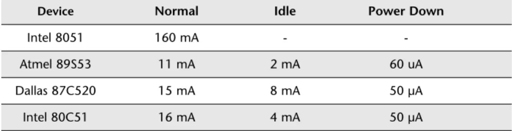
● In most modern (CMOS-based) 8051s, there is an almost linear relationship between the oscillator frequency and the power supply current. As a result, by using the lowest frequency necessary it is possible to reduce the power require-ment: this can be useful, particularly in battery-powered applications.
● When accessing low-speed peripherals (such as slow memory, or liquid-crystal displays), programming and hardware design can be greatly simplified – and the cost of peripheral components, such as memory latches, can be reduced – if the chip is operating more slowly.
● The electromagnetic interference (EMI) generated by a circuit increases with clock frequency.
In general, you should operate at the lowestpossible oscillator frequency compati-ble with the performance needs of your application. As we will see in later chapters, simulating the processor is a good way of determining the required oper-ating frequency for a particular application.
2.6 Memory Issues
We consider some of the memory issues relating to the 8051 in this section.
a)
Types of memory
On the desktop, most designers and programmers can safely ignore the type of memory they are using. This is seldom the case in embedded environments, and we therefore briefly review some of the different types of memory below.
First, a short history lesson, to explain the roots of an important acronym. On early mainframe and desktop computer systems, long-term data storage was car-ried out using computer tapes. Reading or writing to the tape took varying amounts of time, depending whether it involved, for example, rewinding the entire tape, or simply rewinding a couple of centimetres. In this context, new memory devices appeared that could be used to store data while the computer was running, but which lost these data when the power was removed. These read-write memory devices were referred to as ‘random access memory’ (RAM) devices, because – unlike tape-based systems – accessing any element of memory ‘chosen at random’ took the same amount of time.
Dynamic RAM (DRAM)
Dynamic RAM is a read-write memory technology that uses a small capacitor to store information. As the capacitor will discharge quite rapidly, it must be fre-quently refreshed to maintain the required information: circuitry on the chip takes care of this refresh activity. Like most current forms of RAM, the information is lost when power is removed from the chip.
Static RAM (SRAM)
Static RAM is a read-write memory technology that uses a form of electronic flip-flop to store the information. No refreshing is required, but the circuitry is more complex and costs can be several times that of the corresponding size of DRAM. However, access times may be one-third those of DRAM.
Mask Read-Only Memory (ROM)
Mask ROM is – from the software developer’s perspective – read only: however, the manufacturer is able to write to the memory, at the time the chip is created, according to a ‘mask’ provided by the company for which the chips are being produced. Such devices are therefore sometimes referred to as ‘factory-programmed ROM’. Mask programming is not cheap, and is not a low-volume option: mistakes can be very expensive, and providing code for your first mask can be a character-building process. Access times are often slower than RAM: roughly 1.5 times that of DRAM.
Many members of the 8051 family are available with on-chip, mask-programmed, ROM.
Programmable Read-Only Memory (PROM)
PROM is a form of Write-Once, Read-Many (WORM) or ‘One-Time Programmable’ (OTP) memory. Basically, we use a PROM programmer to blow tiny ‘fuses’ in the device. Once blown, these fuses cannot be repaired; however, the devices them-selves are cheap.
Many modern members of the 8051 family are available with OTP ROM.
UV Erasable Programmable Read-Only Memory (UV EPROM)
Like PROMs, UV EPROMs are programmed electrically. Unlike PROMs, they also have a quartz window which allows the memory to be erased by exposing the internals of the device to UV light. The erasure process can take several minutes and, after erasure, the quartz window will be covered with a UV-opaque label. This form of EPROM can withstand thousands of program / erase cycles.
More flexible than PROMs and once very common, UV EPROMs now seem rather primitive compared with EEPROMs (see below). They can be useful for pro-totyping but are prohibitively expensive for use in production.
Many older members of the 8051 family are available with on-board UV EPROM.
EEPROM and Flash ROM
Electrically-Erasable Programmable Read-Only Memory (EEPROMs) and ‘Flash’ ROMs are a more user-friendly form of ROM that can be both programmed and erased electrically.
EEPROM and Flash ROM are very similar. EEPROMs can usually be re-programmed on a byte-by-byte basis, and are often used to store passwords or other ‘persistent’ user data. Flash ROMs generally require a block-sized ‘erase’ oper-ation before they can be programmed: often the size of the block will be several kilobytes: such ROMs are often used for the storage of program code.
Many members of the 8051 family are available with on-board EEPROM or flash ROM, and some devices contain both types of memory.
b)
Memory organization and ‘hex’
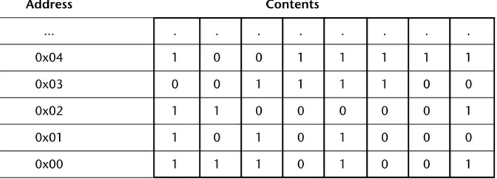
As you will recall, all data items are represented in computer memory as binary codes, each containing a certain number of bits. To simplify the storage and retrieval of data items, these memory bits are organized into memory locations, each with a unique memory address. In a common byte-oriented memory (as used in desktop PCs and – with some exceptions – in the 8051), each memory location contains eight bits (one byte) of storage, and each byte has a unique address (Figure 2.5).
FIGURE 2.5 A segment of byte-oriented memory. Note that each byte(rather than each bit) has its own unique address, shown in hexadecimal notation here. See text for details
Address Contents
... . . .
0x04 1 0 0 1 1 1 1 1
0x03 0 0 1 1 1 1 0 0
0x02 1 1 0 0 0 0 0 1
0x01 1 0 1 0 1 0 0 0
In Figure 2.5, the memory addresses are given in hexadecimal notation. This is a base-16 numbering scheme which provides a compact way of representing large binary numbers: it is widely used in embedded systems. Note that the prefix ‘0x’ is used in C (and elsewhere) to indicate that a number is in ‘hex’ notation.
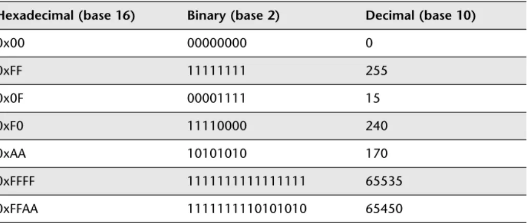
Table 2.1 shows a list of numbers with their hex, binary and ‘ordinary’ decimal representations.
c)
The 8051 memory architecture
Having considered some of the basic memory types available and some general features of computer memory organization, we are now in a position to consider the memory architecture of the 8051.
There are two distinct memory regions in an 8051 device: the DATA area and the CODE area. We will consider each region in turn here.
DATA memory
DATA memory is used to store variables and the program stack while the program is running. The DATA area will be implemented using some form of RAM.
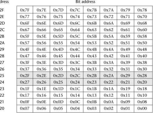
Most of the DATA area has a byte-oriented memory organization. However, within the DATA area is a 16-byte BDATA area which can also be accessed using bit addresses. This area can be used to store bit-sized variables (see Figure 2.6). The 8051 has machine instructions which allow bit variables to be manipulated very efficiently. These instructions can be easily utilized from C, as we will demonstrate in Chapter 3.
26 Embedded C
TABLE 2.1 Different number representations. See text for details
Hexadecimal (base 16) Binary (base 2) Decimal (base 10)
0x00 00000000 0
0xFF 11111111 255
0x0F 00001111 15
0xF0 11110000 240
0xAA 10101010 170
0xFFFF 1111111111111111 65535
Note that the various locations can be accessed either via their byte addresses (0x20 to 0x2F) or via their bit addresses (0x00 to 0x7F).
Note also that there is an area where the bit addresses and the byte addresses are the same. For example, within byte address 0x24, there is a bit location with address 0x27: there is also a byte with address 0x27 in the BDATA area. It may appear that this will cause problems for the compiler. However, no conflicts will arise because the compiler can always determine from the context (that is, the type of data being manipulated) whether the bit address or byte address should be used.
CODE memory
Not surprisingly, the CODE area is used to store the program code, usually in some form of ROM (’read-only memory’).
Please note:
● The CODE area may also contain read-only variables (‘constants’), such as filter co-efficients or data for speech playback.
● On a desktop PC, code is copied from disk to RAM when you run the program. It is then executed from RAM. In most embedded systems, like the 8051, code is ‘executed in place’, from ROM.
Byte
address Bit address
0x2F 0x7F 0x7E 0x7D 0x7C 0x7B 0x7A 0x79 0x78
0x2E 0x77 0x76 0x75 0x74 0x73 0x72 0x71 0x70
0x2D 0x6F 0x6E 0x6D 0x6C 0x6B 0x6A 0x69 0x68
0x2C 0x67 0x66 0x65 0x64 0x63 0x62 0x61 0x60
0x2B 0x5F 0x5E 0x5D 0x5C 0x5B 0x5A 0x59 0x58
0x2A 0x57 0x56 0x55 0x54 0x53 0x52 0x51 0x50
0x29 0x4F 0x4E 0x4D 0x4C 0x4B 0x4A 0x49 0x48
0x28 0x47 0x46 0x45 0x44 0x43 0x42 0x41 0x40
0x27 0x3F 0x3E 0x3D 0x3C 0x3B 0x3A 0x39 0x38
0x26 0x37 0x36 0x35 0x34 0x33 0x32 0x31 0x30
0x25 0x2F 0x2E 0x2D 0x2C 0x2B 0x2A 0x29 0x28
0x24 0x27 0x26 0x25 0x24 0x23 0x22 0x21 0x20
0x23 0x1F 0x1E 0x1D 0x1C 0x1B 0x1A 0x19 0x18
0x22 0x17 0x16 0x15 0x14 0x13 0x12 0x11 0x10
0x21 0x0F 0x0E 0x0D 0x0C 0x0B 0x0A 0x09 0x08
0x20 0x07 0x06 0x05 0x04 0x03 0x02 0x01 0x00
● One consequence of the ‘execute in place’ operation is that, in most applica-tions, while you may require up to 10 kbytes of CODE memory, you will rarely need much DATA memory. This is reflected in the fact that many 8051 devices have 20 kbytes or more of on-chip ROM, but will often have no more than 256 bytes of RAM. This is an appropriate mix for most general applications.
d)
8-bit family, 16-bit address space
The Standard 8051 can be described as an 8-bit microcontroller with a 16-bit address space.
Here the fact that it is an ‘8-bit microcontroller’ refers to the size of the registers and data bus. This means that the family will handle 8-bit data very quickly and process 16-bit or 32-bit data rather less efficiently.
The 16-bit address space means that the device can directly address 216bytes of
memory: that is, 64 kbytes. Note that the (Harvard-like) architecture of the 8051 means that it can access both 64 kbytes of CODE memory and 64 kbytes of DATA memory. These figures refer to the total amount of memory you can access: to reach these limits, you will need to connect memory devices to the external inter-face (Figure 2.7).
28 Embedded C
FIGURE 2.7 The 8051 external memory interface. Use of this external memory interface involves the use of the whole of Port 0 and Port 2, plus some of Port 3. We will not consider hardware issues in detail in this book: please refer to Chapter 11 for sources of further information about this topic
Timing and control lines 8-bit data bus
8-bit address
bus 8-bit (upper) address bus
Where possible, it is better to use a device with all the required memory on the chip: this can improve reliability, reduce costs, reduce the application size, and reduce power consumption.
Finally, please note that – while all 8051s are 8-bit microcontrollers – some more recent devices (like the Dallas 80c390) support an address space greater than 16 bits. This allows access to much larger amounts of memory. Please refer to the 80c390 data sheet (on the CD) for details.
2.7 I/O pins
Much of the activity in embedded systems involves reading pins (which may, for example, be connected to switches or keypads) and altering the value of other pins (which may, in turn, control anything, from an LED to a 5-tonne industrial robot). The 8051 architecture has a number of features which make it very well suited to such applications.
Most 8051s have four 8-bit ports, giving a total of 32 pins you can individually read from or control. All of the ports are bidirectional: that is, they may be used for both input and output. To limit the size of the device, some of the port pins have alternate functions. For example, as we saw in the previous section, Ports 0, 2 (and part of Port 3) together provide the address and data bus used to support access to external memory. Similarly, two further pins on Port 3 (Pin 16 and Pin 17) also pro-vide access to the on-chip UART (see Section 2.10). When in their ‘alternative roles’, these pins cannot be used for ordinary input or output. For example, if using a Standard 8051 device with external memory, Port 1 is the only (complete) port available for general-purpose I/O operations.
The comments above all refer to the Standard 8051: the number of available ports on 8051 microcontrollers varies enormously: the Small 8051s have the equivalent of approximately two ports, and the Extended 8051s have up to ten ports. Despite these differences, the control of ports on all members of the 8051 family is carried out in the same way.
We will consider how to use the port pins for input and output in Chapter 3 and Chapter 4.