Corresponding Author: Jer-Vui Lee, Department of Mechatronics and Biomedical Engineering, Faculty of Engineering and Science, Universiti Tunku Abdul Rahman, Jalan Genting Kelang, 53300 Kuala Lumpur,
Pick-and-place Machine Design with Vision Module
1Yea-Dat Chuah, 1Jer-Vui Lee, 2Yeong-Jin King and 1Jon-Wen Tan
1Department of Mechatronics and Biomedical Engineering, Faculty of Engineering and Science,
Universiti Tunku Abdul Rahman, Jalan Genting Kelang, 53300 Kuala Lumpur, Malaysia. 2Department of Mechanical and Material Engineering, Faculty of Engineering and Science,
Universiti Tunku Abdul Rahman, Jalan Genting Kelang, 53300 Kuala Lumpur, Malaysia.
Abstract: This paper presents the design and development of a pick-and-place machine for integrated circuit (IC) packages. This paper begins with the conceptual design and its design considerations. A stress simulation has been carried out on the pickup arm. In the hardware part, several components are carefully selected or custom designed, fabricated and assembled for the electronics system, pneumatic system and mechanical system. In the software part, a graphical user interface (GUI) has been developed using MFC in C++ programming language. The performance of the machine has been tested in terms of pick-and-place speed and placement repeatability. The outcome was a pick-and-place machine that is capable to achieve speeds of up to 1500UPH using a simple design and readily available industrial components.
Key words: Pick-and-Place Machine, Machine Design and Vision Module
INTRODUCTION
Achieving High Speed Component Pick-and-place:
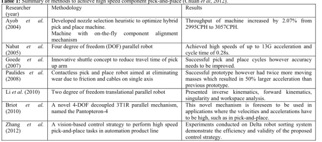
Machine set-up and precision are critical to the efficiency of the high speed pick-and-place machines’ operation. It requires the evaluation and control of many parameters (Koepp et al, 2008). Proper machine set-up requires highly experienced technicians or engineers. There are various designs to achieve precise pick-and-place. Table 1 summarizes the various methods proposed by different researchers to achieve high speed pick- and-place (Chuah et al, 2012).
Vision Inspection system is one of the commonly used tool in industry (Patrick, 1996; Ronald et al, 1999; Brian, 2001; Leigh, 2003; Christine, 2003 & 2009, Piccinini et al, 2012). It consists of a camera, light source, frame grabber, computer and the image processing algorithm. Vision systems require high reliability in order to find out the defects of inspected units. In the actual application, the vision system is a sub-module mounted on the IC test handler. More than 20,000 Units Per Hour (UPH) passes through the vision systems and the ICs are constantly being moved from one inspection station to another. Consumer demand for electronic products like smart phones and tablet computers have been steadily increasing, it makes extremely heavy demands in the electronics manufacturing industry. High speed vision systems are required to inspect integrated circuit (IC) packages as small as 2mm × 2mm. Current commercial IC test handlers which include IC inspection have reached speeds in excess of 20,000 units per hour (UPH) and its vision systems require the support of reliable software (Chuah et al, 2012).
Table 1: Summary of methods to achieve high speed component pick-and-place (Chuah et al, 2012). Researcher
(year) Methodology Results
Ayob et al.
(2004) Developed nozzle selection heuristic to optimize hybrid pick and place machine. Machine with on-the-fly component alignment mechanism
Throughput of machine increased by 2.07% from 2995CPH to 3057CPH.
Nabat et al. (2005)
Four degree of freedom (DOF) parallel robot Achieved high speeds of up to 13G acceleration and cycle time of 0.28s.
Goede et al. (2007)
Innovative shuttle concept to reduce travel time of pick up arm
Successful pick and place cycles however accuracy needs to be improved.
Paulides et al. (2008)
Contactless pick and place robot aimed at eliminating wear due to friction and cables on single axis
Successful prototype however had twice more moving masses which resulted in 50% larger acceleration than previous prototype.
Li et al. (2010) Two degree of freedom translational parallel robot Presented inverse kinematics, forward kinematics, singularity and workspace analysis.
Briot et al. (2010)
A novel 4-DOF decoupled 3T1R parallel mechanism, named the Pantopteron-4
This novel mechanism is foreseen to be used in applications where the velocities and accelerations have to be high, such as in pick-and-place.
Zhang et al. (2012)
A vision-based control strategy to perform high speed pick-and-place tasks in automation product line
Conceptual design:
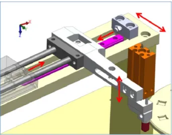
Conceptually, the overall design of the machine is shown in Figure 1. The IC packages are placed in an indexing plate and rotated for the pickup arm to sequentially pick and return each unit. The X-axis movement is achieved by using one pneumatic cylinder and the Z-axis movement is achieved by using another cylinder. A linear guide is used to ensure the movement is guided in an exact line and also to withstand the moment on the X cylinder due to the pickup arm. This method was found to be the simplest in terms of control and simplicity. End-to-end movement is transferred using cylinders and unit changing using a stepper motor. Figure 2 shows the complete design of the machine which excludes the vision system and control elements (Chuah et al, 2012).
Fig.1: Conceptual design.
Fig. 2: The complete design in isometric view.
Design Considerations:
In the design, additional tolerance areas are added for alignment purposes. These considerations allow for time saving during the assembly and calibration process. The extra alignment tolerances also allow the machine to support different type of IC packages with minor adjustments. Generally, there are 3 rules that are considered which allow extra tolerance (Chuah et al, 2012).
i. Not all the parts should be free for alignment because it will introduce uncertainty during the assembly process. The more fixed parts, the better.
ii. In order to make for the machine to function properly. The additional tolerance for the alignment should be allocated as near as possible to the section where the alignment is critical.
iii. The alignment should only be allowed along or around one axis in each position where tolerance is given.
Figure 3 shows the places where alignment is allowed for the X, Y and Z axis. In order to constrain the movement of component, grooves and specific cut-outs are designed which help to reduce the overall alignment time.
Fig. 3: Locations for alignment of pickup head.
Component Selection:
The stepper motor selected is a 2-phase step motor by Tamagawa (TS3653N94E5). There are two main cylinders that are used for the actuation in the X-axis and the Z-axis. For the X-axis cylinder, the CXSJ series by SMC is selected since it is a compact type dual cylinder which allows for higher actuation forces to move the pick-up arm. The model selected is CXSJL10-70 which has a 10mm bore size, 6mm rod size (standard for 10mm bore) and 70mm stroke. The piston area is doubled since there are 2 cylinders. Therefore, the force was calculated to be approximately 78.5N when the operating pressure is 0.5MPa. For the Z-axis actuation, the force required is not an important parameter since the units are relatively light (less than 100grams). However it is important to ensure the cylinder rod is guided properly in order to keep its straightness. The rod must also be non-rotating in order to avoid the units from rotating out of orientation. The cylinder CDUK6-15D by SMC was selected to for this purpose. It contains a stainless steel block at the end and a linear guide rod to avoid the rod from rotating. The linear guide is used to hold the pickup arm in place. It also ensures that most of the moment caused by the pickup arm is supported by the guide instead of the pneumatic cylinder. A stainless steel linear guide (SSEBL-N8-119 and is sold by Misumi) was selected with one block for the mounting of the pickup arm.
To achieve high speed actuation, a quick response is required. The valves play an important role in transferring the air to the cylinders. It acts as a switch to control the movement of the cylinders. The valves selected for this machine are standard 5/2 way valves (SY3000 series by SMC) which stands for five ports for airflow and two positions which can be switched depending on the requirement. A vacuum module (ZX1071-K15LZ by SMC) was selected which contains all the required components to generate vacuum, ejector, valve and a filter to avoid the valve from being contaminated. This module is able to pick the electronic components up to 100g.
Stress Simulation On Pickup Arm:
Fig. 4: Stress simulation of pickup arm.
Pneumatics System:
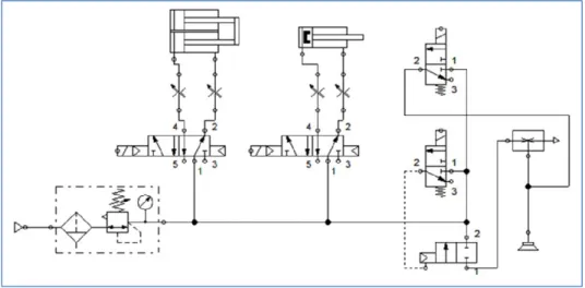
Figure 5 shows the block diagram of the pneumatic system. It comprises of two cylinders, one regulator and one vacuum module. Other parts include the elbow type speed controller, M5 fittings, Y and T junction fittings and tubing. The connection of all the components were modeled in Festo FluidSim software and simulated before the actual system was developed. The components on the right form the vacuum module where two inputs are required to switch on or off the vacuum and purge (blow air to remove unit). The components on the left are the air regulator while the components in the middle are the valves and cylinders. Overall, this simple pneumatic system is able to deliver the functionality required by the machine.
Fig. 5: Pneumatic block diagram.
Electronics:
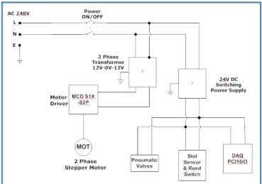
The overall connection block diagram is shown in Figure 6. The power supply supplies 240V AC to the machine via a standard three-pin plug. A step down transformer and a switching supply are used to step down the high voltage. 24V DC is the operating voltage of all the components used except for the motor driver which requires a 12-0-12V two-phase AC. The machine logic also operates on a 24V DC voltage and a compatible Data Acquisition Unit (DAQ-PCI16IO by Vie Technologies) is applied for Input and Output (IO). The motor driver selected is the MCD S1X-S2P by Vie Technologies. Its input voltage is 12-0-12V and its driving voltage is ranged from 34V to 36V with maximum current up to 4A.
for this machine is the D-A93 model by SMC. It is a two wire type connection that forms a closed circuit when magnet is present. The response time for this switch is 12ms.
Fig. 6: Electronic connection block diagram.
Software Development:
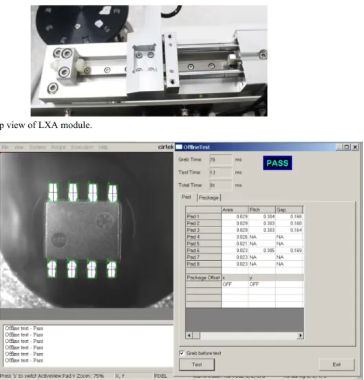
The GUI was designed and developed using Microsoft Visual Studio 2008 (MFC library and the C++ programming language). Figure 7 shows the developed GUI that is used to control the Auto Module. The number of IO Cards detected, base address and slot number the card are exhibited at the top of the GUI. The GUI allows the user to select the board that is connected to the machine. Generally, the application is divided into four different groups of control boxes. The button in the first group is used to start/end the program sequence. This is an automatic sequence which runs accordingly to the developed C++ program. The next two control boxes allow the user to control certain outputs manually. The manual output box can be used to control the cylinder movements, vacuum, purge and trigger the vision signal. These buttons allow the user to pick and hold a unit in a desired position manually. The motor control allows the user to make the indexer and step the indexer plate to home positions. The five outputs are used to manually control the motor for troubleshooting purpose. The final group of control box shows the digital input. It is also used for troubleshooting purpose and aware the user to response on the various outputs from the machine.
Fig. 7: Machine tester application graphical user interface.
1
2 3
RESULTS AND DISCUSSION
Overall Design:
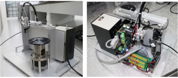
The final product is a fully functional pick-and-place machine that is controlled by an application on windows. Table 2 summarizes the general specifications of the machine. Figure 8 shows the isometric view of the pickup arm and the pickup head at the home position. The tube extends out from the left is the input for the compressed air supply. The black cable on the right is the power cable while the grey cable is connected to the DAQ card.
Table 2: Machine specifications.
Overall Dimensions 400mm(L) × 340mm(W) × 340mm(H)
Overall Mass 9kg
Input Voltage 240V AC
Operating Voltage 24V & 12-0-12V
Operating Pressure 0.5Mpa
Maximum Vacuum Pressure -91kPa
Rated Speed 1500 UPH
Figure 9 shows the top-back view of the final product. The power supply box, motor stepper and driver, IO termination board, valves, air regulator and vacuum module are exhibited in this figure. All of the control components are placed at the back of the machine since the operator doesn’t use it. The vision module is mounted on the six holes that are located in front of the pickup arm. Figure 10 shows the machine attached with a vision module. The lighting effects of the vision system can be observed. The light is a high intensity flash and can be tuned in various colours, depending on the unit inspected. Therefore, components that are closed to the vision system need to be black in colour for absorbing the stray reflections.
Fig. 8: Isometric-front view of the machine. Fig. 9 : Top-back view of the machine.
Figure 11 shows the pickup head and arm where alignment can be done and the height can be adjusted. The arm is also hollow in the middle to decrease the overall inertia. The indexer is in its home position where the dog is slightly beside the photoelectric slot sensor.
Fig.10 : Machine with vision module in place. Fig.11 : Pickup head and indexer disc with photoelectric slot sensor.
The LXA module is an important part where it ensures the rigidity of the pickup arm during the motion. Figure 12 shows the top view of the pickup arm which is attached to the linear guide below it. The X-axis cylinder is located on the right of the image and it is also connected to the pickup arm at the end of the cylinder. The image captured and image processing of the unit is beyond the scope of this paper. However Figure 13 illustrates how a typical captured image when and measurements were conducted.
Fig. 12 : Top view of LXA module.
Pick and Place Speed:
For standard evaluation of the developed machine, a total of ten similar IC units were used and each unit was inspected nine times. This brought a total of 90 times to be considered as one full cycle. The speed of the machine was measured using a sport timer watch from the click of “Run Sequence” button until the X-cylinder returned to its home position. The vision cycle time was assumed 100ms for each unit.
Table 3 shows the results of recorded time. The average time for the machine to complete the pick-and-place for 90 units is 215.33s.The UPS is calculated to be 0.4180 units/s and the UPH is calculated to be 1504 units/h. The trial run was conducted more than 20 times and the recorded time was found to be within ±0.1% of the average time. The speed did not achieve the expected 2000UPH due to several reasons. Firstly, there was a defective cylinder which leaked the air in one direction, causing the return stroke to be slower that it should be. Higher speeds will cause high machine vibration due to the impact of stopping the cylinders. The high impact forces may reduce the lifespan of the machine. This problem can be reduced by introducing shock absorbers instead of the current nylon bolt that is used as a stopper.
Secondly the developed software for the machine was not fully optimized at the current stage. The software functions based on a delay so the extra time may be wasted in waiting for the delay to elapse. There were also not enough sensors to assist the software to indicate the states of the machine before proceeding to the next step.
Table 3: Pick and place time (s) for 90 units.
Trial number Recorded Time (s)
1 215.33 2 215.41 3 215.25 Average 215.33
Placement Repeatability:
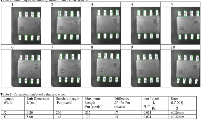
In order to visualize the placement repeatability of the machine, the vision system was used to capture the images of the unit at the inspection position. A series of 10 units was used and each unit’s image was captured. The images were captured using the Bottom-Pad Vision. It can be observed from the ten images as shown in Table 4, the unit’s position slightly moves around and rotates slightly either to the left or right. The position of the suction pad can be seen in the image (the round circle behind the unit). The lighting of the vision illuminates the vacuum pad. In the real application, this is undesirable and it may affect the image processing. To obtain the error, the image was zoomed to 400% size and measured using pixel ruler then the mm/pixel value and error were calculated. Table 5 shows the result of the calculated mm/pixel value and error.
Table 4: Unit images captured by Bottom-Pad Vision System.
1 2 3 4 5
6 7 8 9 10
Table 5: Calculated mm/pixel value and error. Length/ Width Unit Dimension L (mm) Standard Length Po (pixels) Maximum Length Pm (pixels) Difference ∆P=Po-Pm (pixels)
mm / pixel Error
X 6.20 200 217 17 0.031 ±0.26mm
Y 5.00 162 176 14 0.031 ±0.22mm
then multiplied with the mm/pixel ratio and divided by two to obtain the error. The error is the possible misalignment in terms of position in the X and Y axis.
Possible Areas of Improvement:
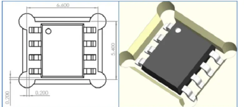
From the tests, it can be observed that the units tremble and shake in its pocket during the stepper motor rotates to the next position. It is because too much tolerance allowed in the design of the indexer disc. Figure 14 shows the layout and space between the unit and the walls of the disc pocket. On the left, a 2D drawing and dimension difference between the unit and pocket is shown. A 3D visualization is shown on the right. From the results, it shows that ±0.2mm tolerance for both sides (left/ right and top/ bottom) is too wide which allows for too much movement when the indexer rotates. A suggested tolerance of ±0.05mm each side should be sufficient to reduce the misalignment. Table 6 shows the expected improvements if the new pocket design is implemented.
Fig. 14: 2D and 3D image of available tolerance between unit and pocket.
Table 6: Expected improvements after implementation of new pocket design. Length/ Width Initial Error (mm) After change in indexer
pocket dimensions
Expected Improved Error
X 0.26 ≈ ±0.065mm 65 microns
Y 0.22 ≈ ±0.055mm 55 microns
Conclusion:
An automated machine has been designed and developed which performs pick-and-place with vision inspection. After the activation of a button, the machine automatically pick the units, place on the indexer disc and move it to the required location for inspection then place it back in its original position. It has a capacity of 10 units and can also be re-programmed to pick-and-place fewer than 10 units. The developed machine achieves speeds of 1500UPH. This speed falls short of the initial target of 2000UPH. This is due to several mechanical limitations. The speeds of the pneumatic cylinders are limited to about 50% of their actual speed. If the impact from the cylinder stopping can be reduced, the speed can be increased greatly by cutting down the overall cycle time for cylinder movement. Software optimization can be carried out in order to increase the speed. In addition, the GUI of the machine has been developed using MFC in C++ programming language. The developed application has the basic functionalities to execute the sequence and manually trigger each output for the pneumatics component and the stepper motor. All the machine output signals are exhibited in the application interface.
REFERENCES
Ayob, M., and G. Kendall, 2004. A nozzle selection heuristic to optimise the hybrid pick and place machine, IEEE Conference on Cybernatics and Intelligent Systems, 2: 1260-1265.
Brian Rooks, 2001. Manufacturing week targets assembly and vision, Assembly Automation, 21(2): 117-122.
Briot, S. and I.A. Bonev, 2010. Pantopteron-4: A new 3T1R decoupled parallel manipulator for pick-and-place applications, Mechanism and Machine Theory, 45: 707-721.
Christine Connolly, 2003. Using machine vision in assembly applications, Assembly Automation, 23(3): 233-239.
Christine Connolly, 2009. Machine vision advances and applications, Assembly Automation, 29(2): 106-111.
Chuah, Y.D. and J.W. Tan, 2012. Machine design for Gauge Repeatability and Reproducibility measurement of vision modules, 2012 IEEE Conference on Sustainable Utilization and Development in Engineering and Technology (Student), 6-9.
Koepp, R., T. Allen, J. Fassett & A.T. Tang, 2008. Achieving high speed RFID die pick and place operation, IEEE/CPMT International Electronic Manufacturing Technology Symposium (IEMT), 1-8.
Leigh Simpson, 2003. Machine vision improves productivity in many ways, Assembly Automation, 23(3): 243-248.
Li, Z., Y. Lou, Z. Li, G. Yang, & J. Gao, 2010. A novel two degree of freedom translational parallel robot for pick and place operation, 8th IEEE International Conference on Control and Automation, pp: 725-730.
Nabat, V., M. Rodriguez, O. Company, S. Krut, & F. Pierrot, 2005. Very high speed parallel robot for pick and place. IEEE/RSJ International Conference on Intelligent Robots and Systems, pp: 553-558.
Patrick Hillberg, 1996. A vision-guided robotic water jet cutting system, Assembly Automation, 16(2): 17-21.
Paulides, J., L. Encica, J. Jansen, R. v. Burg, J. Horijon, & E. Lomonova, 2008. Robot architecture for a contactless industrial pick and place machine. International Conference on Electrical Machines and Systems, 2954-2959.
Piccinini, P., A. Prati and R. Cucchiara, 2012. Real-time object detection and localization with SIFT-based clustering. Image and Vision Computing, 30: 573-587.
Ronald Brian Jennings and Glen Bright, 1999. Machine vision and intelligence incorporating motion control, Assembly Automation, 19(1): 55-58.