Exploring Dielectric Absorption: Data Collection System Development
Avery Ted Cashion IV
A thesis submitted to the faculty of the University of North Carolina at Chapel Hill in partial fulfillment of the requirements for the degree of Master of Science in the Department of Biomedical Engineering.
Chapel Hill 2010
©2010
ABSTRACT
Avery Ted Cashion IV: Exploring Dielectric Absorption: Data Collection System Development
(Under the direction of Robert Dennis, PhD)
Dielectric materials in capacitors restore charge to the capacitive plates following a momentary short of the terminals by an effect known as dielectric absorption.
TABLE OF CONTENTS
List of Figures………...……….…………. v
Introduction………...……….……. 1
Materials and Methods………...……….……… 5
Results………..……….…… 14
Discussion………..……….…….. 15
Future Research………..………...17
Conclusions………...………17
Appendix...………...…….………18
LIST OF FIGURES
Figure
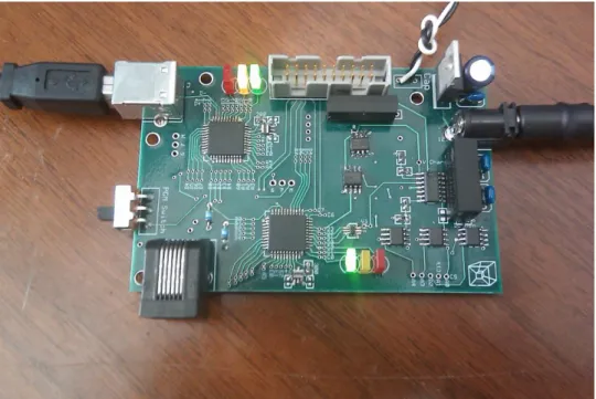
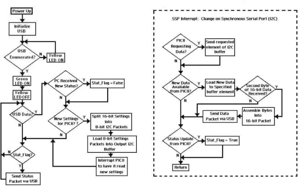
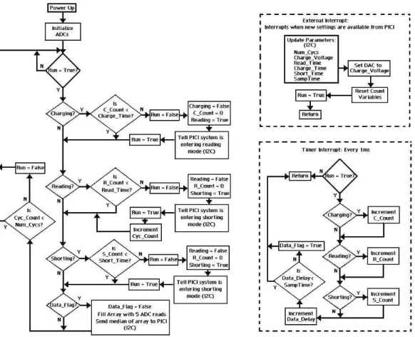
1. Representation of a single data collection cycle….………6 2. Image of the system hardware..………..6 3. Circuit schematic for generation of charge signals and acquisition of data…...6 4. Program flow diagram for the USB intermediary chip (PICI)……...……...11 5. Program flow diagram for PICII, the microcontroller that
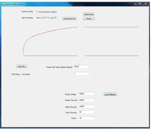
directly controls data collection parameters…….……….12 6. Data collection software GUI………...…….………...13 7. Example data collected with this system on commercial
Introduction
Dielectric absorption describes an intrinsic property of dielectric materials wherein the charge on a capacitor returns to a certain degree after briefly shorting the terminals. Dielectric theory suggests that this behavior stems from a gradual polarization of the molecules of the dielectric material in the presence of an electric field [1]. After the removal of the externally applied electric field (shorting), the remaining dipoles set up in the dielectric still have an electric field of their own. This field in turn restores some charge to the capacitive plates as the induced dipoles decay over time in the absence of the initial electric field placed on the capacitor. The rate and final value of the returning charge is dependent mainly on the molecular structure of the dielectric material involved.
voltage/high power systems, capacitors must often be discharged several times before they can be safely handled.
To better understand this phenomenon, an absorption-compensating mathematical model of a capacitor has been described using a succession of RC circuits connected in parallel with the original capacitor [3]. The RC circuits mimic dielectric absorption behavior by representing delayed release energy storage elements. The number of RC components and the R and C values of each must be experimentally estimated in each case.
Minimization of this effect is an important criterion in the selection of dielectric materials by capacitor manufacturers. Some common dielectrics include mylar, silver mica, and ceramic but for better absorption performance, polypropylene or PTFE (Teflon) is used [2]. Nonetheless, these carefully chosen materials for industrial
capacitors still provide a readily measurable charge soakage signal with relatively simple electronics. The system described here employs a method for measurement of this property adapted from a design by Robert Pease wherein a strip chart recorder was used to characterize some absorption behaviors of different dielectrics [1].
Sensor applications based on other dielectric behaviors have been applied
successfully in several ways. One common use for dielectric technology is in the design of gauges for monitoring the fluid level in a container, such as diesel fuel, hydraulic fluid, or motor oil. Two long parallel plates coated in a nonconductive material are placed vertically into the container with a small gap between them to form a variable capacitor. As the fluid fills the volume between the plates, it displaces the air and acts as a
capacitance between the plates rises as fluid is added to the container. This is a very reliable method for measuring fluid level but it provides little information about the fluid itself.
“Dielectric spectroscopy” generally refers to the observation of dielectric behavior at carefully selected sinusoidal frequencies to determine specific dielectric material properties. One use of dielectric spectroscopy relevant to biologically derived fuels is a method of determining biomass concentration in suspended cultures of microorganisms using a capacitive probe [4-5]. The process works by selecting a capacitor charge frequency based on the dielectric dispersion principles of biological cells [4-7]. Conductivity and permittivity data, obtained by monitoring conductance of the sample and capacitance of the probe, can be used with a series of equations defined by [Harris et. al] to determine the volume fraction of the sample that is inhabited by cells [4]. Biomass concentration is the most established measurement with this technology but some results suggest other capabilities through the use of harmonics derived from a Fourier transform of the signal [5].
Potential applications of a sensor based on dielectric absorption to provide rapid
determinations of bulk sample characteristics are widely varied. Preliminary experiments suggest one possible application of this method in the rapid assessment of oil content in cultures of algae.
Assessment of oil productivity (mass of oil per unit volume of algal broth) is of critical importance to algae-derived bio-fuels research. The oil content of the cells is both strain-specific and highly dependent on environmental growth conditions [10]; genetic and metabolic engineering are also likely to have a significant effect in the future [13]. Metrics developed for this type of measurement are mainly limited to theoretical yield calculations based on multiple efficiency assumptions [11, 12], and experimentally determined weight percentage of algal lipids versus dried biomass [9-12]. Though theoretical approaches provide a valuable means for qualitative estimation of algal oil possibilities, actual oil productivity measurements must be collected to facilitate the necessary incremental research in this field. Percent lipids by weight measurements are currently energy intensive and require relatively large samples of algae. A capacitive probe based on dielectric absorption may help to fill this technological void in bio-fuels research.
Though dielectric absorption is an undesirable characteristic of real capacitors in most electronic applications, details of this behavior will be exploited in the work described in this thesis in order to gain deeper understanding and explore other possible applications of the phenomenon. Data collected with this device is being used to
Materials and Methods
System Overview
According to the existing dielectric absorption model [3], the rebuilding voltage on a capacitor induced by a saturated dielectric is a time-dependent function of the initial charge voltage and the duration of the short. Conversely, in a briefly charged capacitor the decaying voltage resulting from soakage into the dielectric is described as a function of charge time and charge voltage.
To enable low frequency and “DC” dielectric soakage measurements in accordance with this model, we have selected five user defined parameters for data collection settings in this system: charge voltage, charge time, short time, read time and number of data cycles. See Figure 1 for a description of how these parameters relate to the voltage signal being digitized. One data collection cycle includes three modes of data collection. When the system is in charging mode the positive terminal of the subject capacitor is connected to the charge voltage. The charge voltage is disconnected and the capacitor is shorted during shorting mode. Finally, the system transitions into read mode where the capacitor charge is building and is connected exclusively to the data collection circuitry.
Fig 1. Representation of a single data collection cycle. The graph displays an example voltage on a capacitor over time in this system. All parameters are 16-bit values allowing user settings in the range of 0 to 65534. A charge voltage setting of 65534 will yield a 10v output in the circuit. Each time variable signifies the amount of time in milliseconds that the system will be in that data collection mode during each cycle (Charge time means time in charging mode etc.)
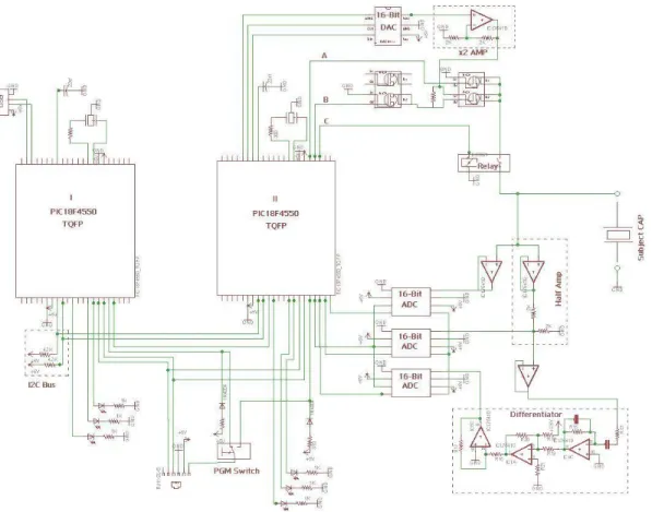
Fig. 3. Circuit schematic for generation of charge signals and acquisition of data. Created using EAGLE Layout Editor CAD software. Experimental parameters set in software control the behavior of the circuit. Three 16-bit ADCs are used to provide options of reading the raw signal, the signal halved (for values in excess of 5V), and/or a differentiated signal.
Charging/Shorting Circuitry
This system is capable of generating DC dielectric soaking signals ranging from zero to ten volts. A 16-bit digital-to-analog converter (DAC8411) is set using SPI communication from a PIC18F4550 microcontroller (labeled II in Figure 1). The output of the DAC is then amplified by a factor of two with a non-inverting operational
A set of three MOSFETs (IRF7341, IRF7343) and a relay (HE3621A051) are used to set the circuit in charge, short, or read modes. The amplified charge signal is connected to the source pin of a P-Channel MOSFET. The P-Ch is activated when the voltage on the gate pin is at least one volt less than that of the source. This means that at source voltages of six volts or more, the P-Ch cannot be controlled by a microcontroller digital I/O pin directly. In light of this constraint, an N-Ch MOSFET serves as an open-collector interface between the microcontroller and the gate of the P-Ch. Thus, activation of the N-Ch (See B in Fig.1) grounds the P-Ch gate and connects the charge signal to the relay. To short the capacitor, line B is pulled low and line A is pulled high. The relay (line C in Fig.1) is in place to completely disconnect the capacitor from the
charging/shorting circuitry during data collection mode to eliminate data aberrations from transistor switching noise. Data is digitized and collected during all modes of operation.
Data Collection Circuitry
After a momentary short of the capacitor terminals, the system is transitioned into reading mode. Depending nonexclusively on the dielectric material, charge voltage, charge time, and short time the charge on the capacitor builds up over a period of several seconds to a voltage value ranging from zero to around 7V. This signal is buffered with a voltage follower op-amp circuit to isolate the reading circuitry with a very high input impedance from the measured signal and thus minimize distortions.
The 16-bit ADCs (TLC4545) allow for three parallel options for signal
the raw signal to be collected with the first ADC for voltages five volts or lower. For values up to ten volts, the second ADC has a one half voltage divider following the buffer. The third acquisition option is an analog differentiated signal. This is in place to offer a measurement of the signal current (first derivative of the voltage). In order to make the differentiated signal comply with the input range of the ADC, a combination of a summing amplifier and an inverting amplifier provides a +2.5V offset.
The ADCs are interfaced via SPI communication from the microcontroller. All three clock lines connect to one I/O pin and the chip select lines connect to another. This allows for simultaneous reading of all three ADCs.
Microcontrollers
Two PIC18F4550 microcontrollers (Labeled I and II in Fig. 1) were used in the hardware design of this system; referred to as PICI and PICII henceforth. All
microcontroller code was written in a C compiler by Custom Computer Services (CCS). PICI acts as an intermediary between PICII and the graphical user interface (GUI) generated in VisualBasic 2010. USB communication on these PICs is relatively
demanding of microcontroller resources, resulting in undesirable design constraints when attempting to implement all the necessary system firmware on a single chip.
request the data from the slave and generate the clock cycles to obtain it. In order to achieve seamless bidirectional data flow in this system, the slave needs to be able to tell the master when data is available to read. This need is addressed with the addition of another connection between the PICs in which a digital I/O pin on PICI is linked to an external interrupt pin on PICII to let it know when data is available to be read. This event triggers the execution of code defined in the external interrupt subroutine on PICII to read the slave device. I2C has a maximum data transfer rate of 3.4 Mbps, sufficient to
facilitate a suitable data sampling rate for digitizing and storing the signal of interest. The design specifications require communication of 16-bit collected data and settings. One limitation of many data transfer protocols, including I2C, is an 8-bit packet size per transfer. Well established methods using binary rotations and software
implementations of logic gates accomplish the splitting and reassembling of the 16-bit integers on each microcontroller.
Graphical User Interface
A text file is created in the user specified directory into which the collected data is logged. The data is written to the first column of the text file and a second “label”
column specifies the data collection mode. A “1” indicates charging mode, a “2” for shorting, and a “3” during data collection mode. The label column provides a simple means for separation of collection modes in the Matlab analysis software as well as a way to display specific sections of the data in real time.
Results
The processor of the PIC18F4550 provides high-speed transfer rates and mathematical functions in working with 16-bit data. Each microcontroller processor is operating at 24.00 MHz in this system. At this clock speed, the system hardware is capable of sampling at a rate of approximately 2.2 KHz. Each successive sample includes reading the ADC five times and loading it into an array, sending the median of the array via I2C, and sending that value to the computer using USB. The hardware sampling rate could be increased by increasing the PIC CPU speed toward the maximum of 48MHz but the limitation in this system is not the hardware, but the GUI sample rate under the Human Interface Device (HID) USB protocol.
Based on experimental testing, the template used in development of the GUI can only read values from a peripheral device at a maximum rate of 125Hz (See Figure 7). This limitation introduces some ambiguity in the time scale of the data being collected at high sample rates. Time between successive data points must be consistent and accurate for analysis methods to work properly. In order to ensure operation in the range of reliability, values are sent to the computer at a rate of once every ten milliseconds
(100Hz). The median filter on PICII lessens the deleterious effect of a lower sample rate because each data point represents five ADC reads. Even with the severe sample rate limitation, the greatest voltage jump between samples seen in any of the data collected during read mode thus far has been less than 2mV, with most step sizes being
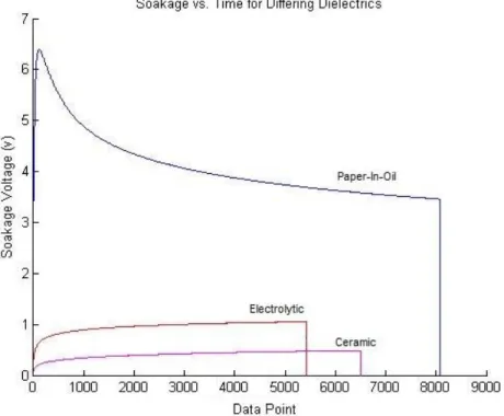
Fig 7. Example data collected with this system on commercial capacitors with differing dielectric materials. The data was separated and rendered in this graph using software created in Matlab 2010 by Devin Hubbard [8]. In this figure, the ceramic capacitor data was collected for 65 seconds at a sample rate of 100Hz. The electrolytic and paper-in-oil (PIO) capacitors were sampled at rates higher than the GUI software can accommodate for read times of 45000 ms and 65534 ms respectively. Dividing the read time by the number of data points collected yields a sample rate of about 124 Hz in both cases.
Discussion
A particular advantage this DC dielectric sensor method has over sinusoidal driven systems is overall simplicity of signal acquisition and analysis. Although sinusoidal systems show potential in being very well catered to specific determinations about a sample, assessment of aggregate characteristics is difficult and each application requires a significant amount of detailed research. The signals generated in dielectric soakage measurements however, provide bulk information about a sample and have been suggested mathematically and supported experimentally to be an average of the
created using similar processes and by simply collecting and referencing the necessary database.
The absorption data collection system described herein can be used to investigate a variety of potential applications of dielectric sensors. Possibilities may include a tool for improvement and testing of industrial capacitors, detection of concealed materials within objects (drugs, explosives, etc), or even a food diagnostic tool for relative
determinations of fat content. It is our hope that collection of data with this system will lead to better sensory technologies in the field of algae-derived bio-fuels.
Future Work
The greatest opportunity for improvement of this system is in the data sampling rate. As the bottleneck occurs in the USB communication between PICI and the
computer, there are viable approaches to this challenge using either software or hardware. Alternative USB techniques exist to the HID method used in this application. Much higher data sampling rates could likely be achieved using a serial port emulation method for example. Another option is adding a memory chip to the hardware that can be interfaced by the microcontroller using a serial communication method. Data could be logged into the memory chip at very high rates but still sent to the GUI in 10ms intervals (100Hz) for real-time plotting. The full dataset could be transferred to the computer after collection is complete.
With a higher sampling rate, another GUI user setting could be created to set the amount of time between samples. This would provide a level of control over the size of the data files being created.
Further design implementations will depend on specific research needs based upon analyses of the data collected with the present system.
Conclusions
This paper describes hardware and software methods for measuring dielectric absorption properties of materials. Microcontrollers, analog-to-digital converters, and fast switching transistors accomplish data logging and data mode settings. The
APPENDIX: Source Code for PICI, PICII, and the Graphical User Interface (GUI)
Source code for PICI:
#include <18F4550.h>
#fuses HSPLL, NOWDT, NOPROTECT, NOLVP, USBDIV, PLL5, CPUDIV3, VREGEN, PUT
#use delay (clock=24000000)
#use i2c(Slave,sda=PIN_B0,scl=PIN_B1,address=0xB2,force_hw,no_stretch)
// PCB board pin defines #define GREEN_LED PIN_C0 #define YELLOW_LED PIN_C1 #define RED_LED PIN_C2
/*
// setup USB endpoints //may not always be necessary #define USB_EP1_TX_ENABLE USB_ENABLE_INTERRUPT
#define USB_EP1_TX_SIZE 32
#define USB_EP1_RX_ENABLE USB_ENABLE_INTERRUPT #define USB_EP1_RX_SIZE 8
*/
// included headers and source code
#include <pic18_usb.h> //Select PIC for USB
#include <usb_desc_hid.h> //USB Application (in this case HID_IO) #include <usb.c> //USB commands. Look through this to understand specifics of commands.
//Special Function Registers///////// #byte TRISB = 0xF93
#bit TrisB0 = TRISB.0 #bit TrisB1 = TRISB.1 #byte SSPBUF = 0xFC9 #byte SSPSTAT = 0xFC7 #bit BF = SSPSTAT.0 #byte SSPCON1 = 0xFC6 #bit CKP = SSPCON1.4 #bit SSPOV = SSPCON1.6 #bit WCOL = SSPCON1.7
/////////////////////////
//Define Globals//
int16 Charge_Time = 20000; //in ms int16 Short_Time = 2000; //in ms int16 Read_Time = 30000; //in ms int16 Voltage = 65534;
int8 buffer_to_16[2]; int1 packet_count = 0; int which_Var = 0;
typedef enum {NOTHING, CONTROL_READ,
ADDRESS_READ, READ_COMMAND_READ} I2C_STATE;
I2C_STATE fState;
BYTE adress, buffer[0x10];
int1 New_Data_Flag = 0; int16 Data;
//The following subroutine Takes a low and high byte and assembles them into a
//single 16-bit number. It is used by first loading your 8-bit numbers into an
//array called "buffer" and then call the command:
//Assemble_16(element number of Low_Byte, element number of High_Byte); //The assembled 16-bit number is returned
int16 Assemble_16(int L_Byte_Add, int H_Byte_Add) { int L_Byte_8; int H_Byte_8; int16 Assembled; int16 Shift; int16 L_Byte_16; int16 H_Byte_16; int16 H_Shifted;
L_Byte_8 = buffer_to_16[L_Byte_Add]; H_Byte_8 = buffer_to_16[H_Byte_Add];
Shift = 256; //2^8 = 256 (Multiplying by 2^8 shifts 8 bits left)
//Turning the 2 8-bit numbers into 16-bit numbers for PIC math operations
L_Byte_16 = L_Byte_8; H_Byte_16 = H_Byte_8;
H_Shifted = H_Byte_16*Shift; //(Multiplying by 2^8 shifts 8 bits left)
Assembled = H_Shifted + L_Byte_16; //Adding the low byte to complete operation
return Assembled;
}
//The following subroutine splits a 16-bit number into its high and low bytes
int Split_16(int16 To_Split, int1 H_or_L){ int16 Shift;
int16 AND16bit; int16 H_Byte_16; int16 L_Byte_16; int H_Byte; int L_Byte;
Shift = 256; //2^8 = 256 (Dividing by 2^8 shifts 8 bits right) AND16bit = 255; //0b0000000011111111
H_Byte_16 = To_Split / Shift; //(Dividing by 2^8 shifts 8 bits right) L_Byte_16 = To_Split & AND16bit; //ANDing with 255 gives you the low byte
//Turning the numbers into 8-bit pieces H_Byte = H_Byte_16;
L_Byte = L_Byte_16;
if (H_or_L ==1){return H_Byte;} if (H_or_L ==0){return L_Byte;} }
//The following subroutine sends a 16-bit number via USB. It actually is sending
//2 individual bytes that you'll have to bring together in software. void USB_Send(int16 Send)
{
out[0]= Send; out[1] = 1007;
usb_put_packet(1,out,2,USB_DTS_TOGGLE); }
//This subroutine reads USB data if it is available. void USB_Read()
{
if (usb_kbhit(1)) { //usb_kbhit is a status bit for available data in input buffer.
usb_get_packet(1,in,4); //Reads the input buffer into array "in" and clears the input buffer.
//2 received 16-bit packets (two updates of the "in" array represents one transmission
//for updating a data setting if(packet_count == 1) {
packet_count = 0;
if(which_Var == 2){ //New Voltage available buffer_to_16[0] = in[0];
if(which_Var == 3){ //New Charge Time available buffer_to_16[0] = in[0];
buffer_to_16[1] = in[1];
Charge_Time = Assemble_16(0,1);
}
if(which_Var == 4){ //New Read Time available buffer_to_16[0] = in[0];
buffer_to_16[1] = in[1]; Read_Time = Assemble_16(0,1);
}
if(which_Var == 5){ //New Short Time available buffer_to_16[0] = in[0];
buffer_to_16[1] = in[1];
Short_Time = Assemble_16(0,1);
}
if(which_Var == 6){ //New # of Cycles available (Also, Cycles is the last update so I2C should be activated
buffer_to_16[0] = in[0]; buffer_to_16[1] = in[1]; Cycles = Assemble_16(0,1);
//Set the new values to be ready to send buffer[2] = Split_16(Charge_Time,0); buffer[3] = Split_16(Charge_Time,1); buffer[4] = Split_16(Read_Time,0); buffer[5] = Split_16(Read_Time,1); buffer[6] = Split_16(Short_Time,0); buffer[7] = Split_16(Short_Time,1); buffer[8] = Split_16(Voltage,0); buffer[9] = Split_16(Voltage,1); buffer[10] = Split_16(Cycles,0); buffer[11] = Split_16(Cycles,1);
//interrupt master and tell it to read in new values output_high(PIN_B2);
delay_ms(1);
output_low(PIN_B2); }
which_Var = 0; }
if (packet_count == 0){ if (in[0]>1) {
packet_count = 1; //Set packet_counter flag to indicate that a setting is being received.
which_Var = in[0];
//output_toggle(YELLOW_LED);
if (in[0]==0) {output_low(RED_LED);} //Turns red LED off } } } #INT_SSP void SSP_isr() {
BYTE incoming, state, clear; state = i2c_isr_state();
if (state <= 0x80){ incoming = i2c_read();
if (state ==1){ adress = incoming; //output_high(RED_LED); }
if (state == 2){
buffer[adress] = incoming;
if (adress ==1){ //Second byte of 16-bit data point has been received
New_Data_Flag = 1;
buffer_to_16[0] = buffer[0]; buffer_to_16[1] = buffer[1]; Data = Assemble_16(0,1); USB_Send(Data);
}
if (adress ==2){ //Status byte has been updated buffer_to_16[0] = buffer[2];
buffer_to_16[1] = 0;
Status = Assemble_16(0,1); USB_Send(Status); output_toggle(YELLOW_LED); } } }
if (state == 0x80){ //TrisB0 = 1;
//clear = i2c_read(); i2c_write(buffer[adress]);
//SSPBUF = 0;
//i2c_write(0b00000111); //BF = 0;
// CKP = 0;
//output_high(RED_LED); }
}
void main (void) {
// initialize variables int i;
int Test_H; int Test_L;
fState = NOTHING; adress = 0x00;
for (i=0;i<0x10;i++){ buffer[i] = 0x00;}
enable_interrupts(INT_SSP); enable_interrupts(GLOBAL);
// initialize USB usb_init(); //initialize ADC // adc_init(); //output_high(Charge_Relay);
while (TRUE) {
if (usb_enumerated()) //USB must be enumerated (PC ack) for any USB communications
{
output_high(GREEN_LED); //output_low(YELLOW_LED); USB_Read();
if(Voltage == 500 && Charge_Time == 1000 && Read_Time == 2000 && Short_Time == 4000 && Cycles == 8000){
output_toggle(YELLOW_LED); delay_ms(250);
}
if(New_Data_Flag ==1){ New_Data_Flag = 0; //USB_Send(Data);
// output_toggle(PIN_E0); }
}
else //USB not enumerated {
} } }
Source code for PICII:
#include <18F4550.h>
#fuses HSPLL, NOWDT, NOPROTECT, NOLVP, USBDIV, PLL5, CPUDIV3, VREGEN, PUT
#use delay (clock=24000000)
#use i2c(Master,sda=PIN_B0,scl=PIN_B1,fast)
// included headers and source code
#include <pic18_usb.h> //Select PIC for USB
#include <usb_desc_hid.h> //USB Application (in this case HID_IO) #include <usb.c> //USB commands. Look through this to understand specifics of commands.
//Initialize Slave Addresses
//Initialize Variables int8 Send_Byte = 8;
int8 Slave_One_Address_Write = 0xa0; int8 Slave_Two_Address_Write = 0xb0; int8 data;
int8 i2c_buffer[12];
int16 Charge_Time = 10000; //in ms int16 Short_Time = 500; //in ms int16 Read_Time = 10000; //in ms int16 Voltage = 65000;
int16 Cycles = 10;
int16 USB_VARS[5]; //[charge_time, read_time, short_time, voltage, cycles]
int16 Cyc_Num = 0; int16 analog_in[5]; int H_Byte;
int L_Byte; int1 Go = 0;
////////////////////////////
#define Charge_Cap PIN_D3 #define Short_Cap PIN_D4 #define Cap_Relay PIN_D5 #define DAC_SYNC PIN_D2 #define DAC_CLK PIN_D1 #define DAC_Data PIN_D0
// included headers and source code
#include <pic18_usb.h> //Select PIC for USB
#include <usb_desc_hid.h> //USB Application (in this case HID_IO) #include <usb.c> //USB commands. Look through this to understand specifics of commands.
//Special Function Registers #byte T1CON = 0xFCD
#byte T3CON = 0xFB1
//Defining Globals int8 in[2];
int16 out[2]; int16 ADC_Val;
// initialize variables
int16 analog_center = 0; int16 data_delay = 0; int16 charge_delay = 0; int16 read_delay = 0; int16 short_delay = 0; int16 timer = 0;
int1 charging = 0; int1 reading = 0; int1 shorting = 0; int16 val;
int16 val1 = 0;
////////////////////////////
void Write_Slave(int Slave_Address, int Buffer_Address, Write_Byte) {
i2c_start();
i2c_write(Slave_Address); // Device address
i2c_write(Buffer_Address); // address of the buffer that you are writing to 'buffer[address]'
i2c_write(Write_Byte); //data sent to the buffer(address) above i2c_stop();
delay_us(5); }
int Read_Slave(int Slave_Address, int Buffer_Address) {
i2c_write(Buffer_Address); //i2c_stop();
delay_us(1); i2c_start();
i2c_write(Slave_Address+1); delay_us(2);
data = i2c_read(0);
i2c_stop();
return data;
}
void adc_init() {
int i;
output_high(ADC_CS); // Chip Select (active LOW)
output_high(ADC_CLK); // Serial Clock (active on FALLING Edge) delay_us(1);
// Select ADC Chip
output_low(ADC_CS); // Chip Select (active LOW)
output_high(ADC_CLK); // Serial Clock (active on FALLING Edge) delay_us(1);
// Cycle Serial Clock 4 times with CS = LOW to reset ADC: for(i = 1; i<=4; ++i)
{
output_low(ADC_CLK); // Serial Clock (active on FALLING Edge) delay_us(1);
output_high(ADC_CLK); // Serial Clock (active on FALLING Edge) delay_us(1);
}
}
void Read_16() {
int16 volts = 0b0000000000000000; int bits, c;
volts = 0b0000000000000000;
// Start with ADC INACTIVE
output_high(ADC_CS); // Chip Select (active LOW)
output_high(ADC_CLK); // Serial Clock (active on FALLING Edge) //delay_us(1);
// delay_cycles(2);
// Run 24 cycles of SClk to complete the next conversion for (c = 1; c <=25; ++c)
{
output_low(ADC_CLK); // Serial Clock (active on FALLING Edge) // delay_cycles(2);
}
// Convert and load data.
// Conversion begins on 1st falling edge with MSB first // ... then add 8 falling edges on SClk to complete the next conversion
// Select ADC Chip: initiate conversion cycle output_low(ADC_CS); // Chip Select (active LOW)
output_high(ADC_CLK); // Serial Clock (active on FALLING Edge) // delay_cycles(2);
//The following loop gets a single reading from the adc for ( bits=15; bits>0; bits = bits-1)
{
output_high(ADC_CLK); // Serial Clock (active on FALLING Edge)
// delay_cycles(2);
output_low(ADC_CLK); // Serial Clock (active on FALLING Edge) // delay_cycles(2);
if (INPUT(ADC_IN)) BIT_SET(volts, bits); }
// add 8 falling edges on SCLK to complete the conversion for the next cycle
for (c = 1; c <=9; c = c + 1) {
output_high(ADC_CLK); // Serial Clock (active on FALLING Edge) // delay_cycles(2);
output_low(ADC_CLK); // Serial Clock (active on FALLING Edge) // delay_cycles(2);
}
//De-select the ADC chip
OUTPUT_BIT(ADC_CS, 1); // Chip Select (active LOW)
OUTPUT_BIT(ADC_CLK, 1); // Serial Clock (active on FALLING Edge)
// delay_cycles(2);
ADC_Val = volts; // Set the analog_in value
}
void Get_Data() {
{
Read_16();
analog_in[element] = ADC_Val; // Set the analog_in value }
}
//The following Subroutine gets the median of the analog_in array int16 Median()
{
//Bubble sort Data Array int r,k;
int16 c,Med;
for ( k=0; k <=4; ++k) {
for ( r=0; r <=4; ++r) {
if (analog_in[r] < analog_in[r+1] ) {
c=analog_in[r+1]; // next 3 statements swap 2 values
analog_in[r+1] = analog_in[r]; analog_in[r] = c;
} } }
Med = analog_in[2];
return Med;
}
void DAC_16(int16 Volts) {
int bits, c;
// Start with DAC INACTIVE
output_high(DAC_SYNC); // Sync (active LOW)
output_high(DAC_CLK); // Serial Clock (active on FALLING Edge) delay_us(1);
// Select DAC Chip: initiate conversion cycle output_low(DAC_SYNC); // Sync (active LOW) delay_us(1);
output_high(DAC_CLK); // Serial Clock (active on FALLING Edge) delay_us(1);
//Set Operation mode Normal Operation: (0,0)
output_high(DAC_CLK); // Serial Clock (active on FALLING Edge) delay_us(1);
delay_us(1);
output_low(DAC_CLK); // Serial Clock (active on FALLING Edge) delay_us(1);
output_high(DAC_CLK); // Serial Clock (active on FALLING Edge)
delay_us(1);
OUTPUT_BIT(DAC_Data, 0); //Sets or clears the output bit in accordance with Voltage variable
delay_us(1);
output_low(DAC_CLK); // Serial Clock (active on FALLING Edge) delay_us(1);
//The following loop sends a single 16-bit voltage value to the DAC for ( bits=15; bits>0; bits = bits-1)
{
output_high(DAC_CLK); // Serial Clock (active on FALLING Edge)
delay_us(1);
OUTPUT_BIT(DAC_Data, BIT_TEST(Voltage, bits)); //Sets or clears the output bit in accordance with Voltage variable
delay_us(1);
output_low(DAC_CLK); // Serial Clock (active on FALLING Edge) delay_us(1); }
// add 6 falling edges on SCLK to complete the conversion for the next cycle
for (c = 1; c <=7; c = c + 1) {
output_high(DAC_CLK); // Serial Clock (active on FALLING Edge) delay_us(1);
output_low(DAC_CLK); // Serial Clock (active on FALLING Edge) delay_us(1);
}
//De-select the DAC chip
OUTPUT_BIT(DAC_SYNC, 1); // Sync (active LOW)
OUTPUT_BIT(DAC_CLK, 1); // Serial Clock (active on FALLING Edge)
delay_us(1);
}
//The following subroutine Takes a low and high byte and assembles them into a
//single 16-bit number. It is used by first loading your 8-bit numbers into an
//array called "i2c_buffer" and then call the command:
int16 Assemble_16(int L_Byte_Add, int H_Byte_Add) {
int L_Byte_8; int H_Byte_8; int16 Assembled; int16 Shift; int16 L_Byte_16; int16 H_Byte_16; int16 H_Shifted;
L_Byte_8 = i2c_buffer[L_Byte_Add]; H_Byte_8 = i2c_buffer[H_Byte_Add];
Shift = 256; //2^8 = 256 (Multiplying by 2^8 shifts 8 bits left)
//Turning the 2 8-bit numbers into 16-bit numbers for PIC math operations
L_Byte_16 = L_Byte_8; H_Byte_16 = H_Byte_8;
H_Shifted = H_Byte_16*Shift; //(Multiplying by 2^8 shifts 8 bits left)
Assembled = H_Shifted + L_Byte_16; //Adding the low byte to complete operation
return Assembled;
}
//The following subroutine splits a 16-bit number into its high and low bytes
//It is used by calling "Split_16(16-bit number to split, 0 or 1)" //0 will return Low_Byte and 1 will return High_Byte
void Split_16(int16 To_Split){ int16 Shift;
int16 AND16bit; int16 H_Byte_16; int16 L_Byte_16;
Shift = 256; //2^8 = 256 (Dividing by 2^8 shifts 8 bits right) AND16bit = 255; //0b0000000011111111
H_Byte_16 = To_Split / Shift; //(Dividing by 2^8 shifts 8 bits right) L_Byte_16 = To_Split & AND16bit; //ANDing with 255 gives you the low byte
//Turning the numbers into 8-bit pieces H_Byte = H_Byte_16;
//Interrupt subroutine will be triggered when new USB_Settings are available
//External Interrupt on B2 #INT_EXT2
void ext2_isr() { //i2c_buffer is filled int c;
int i = 0; int n; int r = 0; int j = 1;
for (c = 2; c <=11; c = c + 1){ i2c_buffer[i] = Read_Slave(0xB2, c); i = i+1;
}
for (n = 0; n <= 5; n=n+1){ USB_VARS[n] = Assemble_16(r, j); r = r+2;
j = j+2; }
Charge_Time = USB_VARS[0]; Read_Time = USB_VARS[1]; Short_Time = USB_VARS[2]; Voltage = USB_VARS[3]; Cycles = USB_VARS[4];
DAC_16(Voltage);//Update DAC value charge_delay = 0;
read_delay = 0; short_delay = 0; charging = 0; shorting = 0; reading = 0; Go = 1; Cyc_Num = 0;
output_high(RED_LED); output_low(GREEN_LED); output_low(YELLOW_LED);
if (Charge_Time == 5000 && Short_Time == 5001 && Read_Time == 5002 && Voltage == 65534 && Cycles == 4){output_high(GREEN_LED);}
}
#int_CCP1 //interupts every 1ms void CCP1_isr(void)
{
if(Go == 1){
if(charging == 1){
charge_delay = charge_delay+2; }
read_delay = read_delay+2; }
if(shorting == 1){
short_delay = short_delay+2; }
output_toggle(YELLOW_LED);
//Read_16(); //reads ADC //Split_16(ADC_Val);
Get_Data(); //Fills the Analog_in array to be median filtered //Split ADC value into separate bytes and send them via I2C
val = Median(); Split_16(val);
Write_Slave(0xB2,0,L_Byte); Write_Slave(0xB2,1,H_Byte); }
//val = val+1; // val1 = val1 + 1;
//if(val >= 5 && Go == 1){ // output_toggle(YELLOW_LED);
//Take and send data // Read_16(); //reads ADC
//Split ADC value into separate bytes and send them via I2C //Split_16(ADC_Val);
//Write_Slave(0xB2,0,L_Byte); //Write_Slave(0xB2,1,H_Byte); // val = 0;
//}
// if(val1>=500 && Go == 1){ //Update status // if(reading ==1){Write_Slave(0xB2,2,3);} // if(charging ==1){Write_Slave(0xB2,2,1);} // val1 = 0;
// }
}
#int_CCP2 //interupts every 100us void CCP2_isr(void)
{
//enable_interrupts(INT_CCP1); // disable_interrupts(INT_CCP2); //enable_interrupts(GLOBAL);
//Read_16(); //reads ADC //Split_16(ADC_Val);
// Get_Data(); //Fills the Analog_in array to be median filtered //Split ADC value into separate bytes and send them via I2C // Split_16(Median());
// Write_Slave(0xB2,0,L_Byte); // Write_Slave(0xB2,1,H_Byte); // }
//enable_interrupts(INT_CCP2); }
void main (void) {
ext_int_edge( 2, L_TO_H); // Set up PIC18 EXT2 (PIN_B2) enable_interrupts(INT_EXT2);
setup_ccp1(CCP_COMPARE_INT|CCP_COMPARE_RESET_TIMER); setup_ccp2(CCP_COMPARE_INT|CCP_COMPARE_RESET_TIMER); enable_interrupts(INT_CCP1);
//enable_interrupts(INT_CCP2); enable_interrupts(global);
T1CON = 0b11100101; //Setup Timer1
T3CON = 0b10101101; //Setup Timer3 (use cpu clk, div_by_4, CCP1 = Timer1, CCP2 = Timer3)
// 1/((24000000/4)/4) = .666667us per timer increment
CCP_1 = 1499;//CCP2*.667us = 1ms CCP2 = 1499 for a 1ms interrupt //CCP_2 = 149; //CCP1*.667us = 100us
CCP_2 = 149; //CCP1*.667us = 100us //initialize ADC
adc_init();
delay_ms(250);
//DAC_16(0b1111111111111111);
//USB_VARS[0] = 5000; //in ms //USB_VARS[1] = 5000; //in ms //USB_VARS[2] = 5; //in ms //USB_VARS[3] = 65000; //USB_VARS[4] = 5;
//Short_Time = USB_VARS[2];
output_high(GREEN_LED);
while(TRUE){
//output_high(GREEN_LED); //output_low(YELLOW_LED);
if(charging == 0 && reading == 0 && shorting == 0 && Go == 1){ //Charge_Time = USB_VARS[0];
// Voltage = USB_VARS[3]; // Cycles = USB_VARS[4];
//DAC_16(Voltage);
//disable_interrupts(GLOBAL); Go = 0;
output_low(Charge_Cap); output_low(Short_Cap); output_high(Charge_Cap); output_high(Cap_Relay);
charging =1; //Sets charging flag reading = 0;
shorting = 0;
delay_ms(10);
Write_Slave(0xB2,2,1);//Tell Slave to tell VB that Status is charging
delay_ms(2); charge_delay = 0;
// enable_interrupts(GLOBAL); Go = 1;
}
if(charging == 1 && Go == 1){ // output_high(GREEN_LED); //output_low(RED_LED); // reading = 0;
if(charge_delay >= Charge_Time){
// disable_interrupts(GLOBAL); Go = 0;
charging = 0; reading = 0; shorting = 0; charge_delay = 0;
output_low(Charge_Cap); //
delay_ms(10);
Write_Slave(0xB2,2,2);//Tell Slave to tell VB that Status is shorted delay_ms(2);
output_high(Short_Cap); // Short Cap // delay_ms(10);
shorting = 1; short_delay = 0;
// enable_interrupts(GLOBAL); Go = 1;
}
if (shorting ==1 && Go == 1){ if (short_delay >= Short_Time){
// disable_interrupts(GLOBAL); Go = 0;
shorting = 0; charging = 0; reading = 0; short_delay = 0;
//delay_ms(Short_Time); // Short Time output_low(Cap_Relay);
output_low(Short_Cap); //
delay_ms(10);
Write_Slave(0xB2,2,3); //Tell Slave to tell VB that Status is reading delay_ms(2);
reading = 1; read_delay = 0;
//enable_interrupts(GLOBAL); Go = 1;
} }
if(reading ==1 && Go == 1){ //output_high(RED_LED); //output_low(GREEN_LED); if(read_delay >= Read_Time){
// disable_interrupts(GLOBAL); Go = 0;
reading = 0; shorting = 0; charging = 0; read_delay = 0; delay_ms(10);
Write_Slave(0xB2,2,1);//Tell Slave to tell VB that Status is charging
delay_ms(2);
output_low(Short_Cap); output_high(Charge_Cap); output_high(Cap_Relay); charging = 1;
//delay_ms(10); charge_delay = 0;
// enable_interrupts(GLOBAL); Go = 1;
output_high(GREEN_LED); output_low(RED_LED); output_low(YELLOW_LED); }
else{output_high(RED_LED); output_low(GREEN_LED);}
} }
}
}
Source code for GUI: Imports System
Imports System.IO
Imports System.Windows.Forms
Imports System.Security.Permissions
Public Class Data_Collect
' vendor and product IDs
Private Const VendorID As Short = &H461 'Replace with your device's Private Const ProductID As Short = &H20 'product and vendor IDs ' read and write buffers
Private Const BufferInSize As Short = 5 'Size of the data buffer coming IN to the PC
Private Const BufferOutSize As Short = 4 'Size of the data buffer going OUT from the PC
Dim BufferIn(BufferInSize) As Byte 'Received USB data will be stored here - the first byte in the array is unused
Dim BufferOut(BufferOutSize) As Byte 'Transmitted USB data is stored here - the first item in the array must be 0
' Other Global Varables
Dim Value_In As UInt16 'Concatanated bytes to make a 16 bit value
'Devin's House
Dim DataFileName As String = "C:\Users\dhubbard\Desktop\Cap_Data\test.txt" 'Phillips Computer
'Dim DataFileName As String = "C:\Users\CASE\Desktop\Cap_Data\test.txt"
Dim Take_Data As Boolean = False
Dim Take_Data1 As Boolean = False
Dim count As ULong = 0 Dim count2 As ULong = 0
Dim datafile As New System.IO.StreamWriter(DataFileName, True) Dim Volts As UInt16 = 50000
Dim Charge_tim As UInt16 = 5000 Dim Read_tim As UInt16 = 5000 Dim Short_tim As UInt16 = 500 Dim Cycs As UInt16 = 3
Dim Zer As UInt16 = 0 Dim Status As UInt16 = 0 Dim Next_read As UInt16 = 0 Dim Modflag As Boolean = False
Dim value As UInt16 = 0 Dim value1 As UInt16 = 0 Dim maxholder As UInt16 = 0 Dim minholder As UInt16 = 0 Dim holder As UInt16 = 0 Dim plot_count As Integer = 0 Dim plot_count2 As Integer = 0 Dim stat_flag As Boolean = False
' **************************************************************** ' when the form loads, connect to the HID controller - pass ' the form window handle so that you can receive notification ' events...
'***************************************************************** Private Sub Form1_Load(ByVal sender As System.Object, ByVal e As
System.EventArgs) Handles MyBase.Load ' do not remove!
ConnectToHID(Me)
currentLogFile.Text = DataFileName Voltage_16.Text = CStr(Volts)
Charge_Time_16.Text = CStr(Charge_tim) Short_Time_16.Text = CStr(Short_tim) Read_Time_16.Text = CStr(Read_tim) Cycles_16.Text = CStr(Cycs)
End Sub
'***************************************************************** ' disconnect from the HID controller...
'***************************************************************** Private Sub Form1_FormClosed(ByVal sender As Object, ByVal e As
System.Windows.Forms.FormClosedEventArgs) Handles Me.FormClosed DisconnectFromHID()
End Sub
'***************************************************************** ' a HID device has been plugged in...
'***************************************************************** Public Sub OnPlugged(ByVal pHandle As Integer)
'TextBox1.Text = "Yay"
If hidGetVendorID(pHandle) = VendorID And hidGetProductID(pHandle) = ProductID Then
End Sub
'***************************************************************** ' a HID device has been unplugged...
'***************************************************************** Public Sub OnUnplugged(ByVal pHandle As Integer)
If hidGetVendorID(pHandle) = VendorID And hidGetProductID(pHandle) = ProductID Then
hidSetReadNotify(hidGetHandle(VendorID, ProductID), False) ' ** YOUR CODE HERE **
USB_Label.Text = "Disconnected" End If
End Sub
'***************************************************************** ' controller changed notification - called
' after ALL HID devices are plugged or unplugged
'***************************************************************** Public Sub OnChanged()
' get the handle of the device we are interested in, then set ' its read notify flag to true - this ensures you get a read ' notification message when there is some data to read... Dim pHandle As Integer
pHandle = hidGetHandle(VendorID, ProductID)
hidSetReadNotify(hidGetHandle(VendorID, ProductID), True) End Sub
'***************************************************************** ' on read event...
'***************************************************************** Public Sub OnRead(ByVal pHandle As Integer)
' read the data (don't forget, pass the whole array)... If hidRead(pHandle, BufferIn(0)) Then
' ** YOUR CODE HERE **
' first byte is the report ID, e.g. BufferIn(0)
' the other bytes are the data from the microcontroller...
'Bring two bytes into one 16-bit value, BufferIn(1) = HByte, BufferIn(2) = LByte
value = BitConverter.ToUInt16(BufferIn, 1)
ADC_Val_textbox.Text = CStr(value) TextBox4.Text = CStr(Status)
' The following three if statements ensure help eliminate erroneous data
If Status = 0 Then Take_Data = False 'Fixes false starts
minholder = Math.Min(value, value1) maxholder = Math.Max(value, value1) holder = maxholder - minholder
If value > 4 Then value1 = value
'If stat_flag = False Then If value < 4 And value > 0 Then
Take_Data = False
Modflag = True
plot_count = 10 plot_count2 = 10 stat_flag = True
End If
If Modflag = True Then
Next_read = Next_read + 1 End If
If value = 1 Then
BufferOut(1) = 16 'Tell the PIC that Charging indicator was received
hidWriteEx(VendorID, ProductID, BufferOut(0)) Status = 1
count = 0 count2 = 0 maximumvalue = 0 maximumvalue2 = 0 ReDim data_in(count) ReDim data_in2(count2)
End If
If value = 2 Then
BufferOut(1) = 17 'Tell the PIC that a new Voltage value is available
hidWriteEx(VendorID, ProductID, BufferOut(0)) Status = 2
End If
If value = 3 Then
BufferOut(1) = 18 'Tell the PIC that a new Voltage value is available
hidWriteEx(VendorID, ProductID, BufferOut(0)) Status = 3
End If
'End If
If Take_Data = True And Take_Data1 = True Then
If Status = 3 Then
plot_count = plot_count + 1
If plot_count > 10 Then
data_in(count) = value
If value > maximumvalue Then maximumvalue = value picDataPlot.Refresh()
count = count + 1
ReDim Preserve data_in(count) 'ReDim data_in(count)
plot_count = 0 End If
End If
'End If
plot_count2 = plot_count2 + 1 If plot_count2 > 10 Then
data_in2(count2) = value
If value > maximumvalue2 Then maximumvalue2 = value picDataPlot2.Refresh()
count2 = count2 + 1
ReDim Preserve data_in2(count2) 'ReDim data_in2(count2)
plot_count2 = 0 End If
End If
If Next_read > 2 Then
Take_Data = True
Next_read = 0 Modflag = False
End If
End If
End Sub
'Red Led Toggle
Private Sub Button1_Click(ByVal sender As System.Object, ByVal e As
System.EventArgs) Handles Button1.Click 'BufferOut(1) = 1
If BufferOut(1) >= 1 Then
'TextBox1.Text = "Hello World" End Sub
'Data Filename textbox
Private Sub TextBox1_TextChanged(ByVal sender As System.Object, ByVal e As
System.EventArgs) Handles newFilename.TextChanged 'DataFileName = newFilename.Text
End Sub
Private Sub TextBox2_TextChanged(ByVal sender As System.Object, ByVal e As
System.EventArgs) Handles currentLogFile.TextChanged End Sub
Private Sub TextBox3_TextChanged(ByVal sender As System.Object, ByVal e As
System.EventArgs) Handles ADC_Val_textbox.TextChanged End Sub
Private Sub TextBox4_TextChanged(ByVal sender As System.Object, ByVal e As
System.EventArgs) Handles TextBox4.TextChanged End Sub
Private Sub Label2_Click(ByVal sender As System.Object, ByVal e As
System.EventArgs) Handles USB_Label.Click End Sub
Public Sub Graph_paint(ByVal sender As Object, ByVal e As
System.Windows.Forms.PaintEventArgs) Handles picDataPlot.Paint Dim picturebox_height, picturebox_width As Double
Dim gfx As System.Drawing.Graphics
Dim points() As Point
Dim Control() As Point
Dim graph_1 As Pen
Dim i As Integer = 0 Dim x_centre As Double
Dim y_centre As Double
Dim x_offset As Double
Dim y_offset As Double
On Error Resume Next
x_offset = 10 On Error Resume Next
y_offset = 10 gfx = e.Graphics
picturebox_width = picDataPlot.Width - x_offset picturebox_height = (picDataPlot.Height - y_offset) gfx.TranslateTransform(x_offset, picturebox_height) ReDim Preserve points(count)
ReDim Preserve Control(count) For i = 0 To count
Control(i).X = i * (picturebox_width / (count))
points(i).Y = (-1) * data_in(i) * ((picturebox_height) / maximumvalue)
Next
gfx.DrawLines(Pens.Red, points) gfx.DrawLines(Pens.Blue, Control) End Sub
Public Sub Graph_paint2(ByVal sender2 As Object, ByVal e As
System.Windows.Forms.PaintEventArgs) Handles picDataPlot2.Paint Dim picturebox_height2, picturebox_width2 As Double
Dim gfx2 As System.Drawing.Graphics
Dim points2() As Point
Dim Control2() As Point
Dim graph_12 As Pen
Dim i2 As Integer = 0 Dim x_centre2 As Double
Dim y_centre2 As Double
Dim x_offset2 As Double
Dim y_offset2 As Double
On Error Resume Next
x_offset2 = 10 On Error Resume Next
y_offset2 = 10 gfx2 = e.Graphics
picturebox_width2 = picDataPlot2.Width - x_offset2 picturebox_height2 = (picDataPlot2.Height - y_offset2) gfx2.TranslateTransform(x_offset2, picturebox_height2) ReDim Preserve points2(count2)
ReDim Preserve Control2(count2) For i2 = 0 To count2
Control2(i2).X = i2 * (picturebox_width2 / (count2)) 'Control2(i2).Y = (-1) * 5
Control2(i2).Y = (-1) * ((picturebox_height2) / maximumvalue2) points2(i2).X = i2 * (picturebox_width2 / (count2))
points2(i2).Y = (-1) * data_in2(i2) * ((picturebox_height2) / maximumvalue2)
Next
gfx2.DrawLines(Pens.Red, points2) gfx2.DrawLines(Pens.Blue, Control2) End Sub
'Set File Name
Private Sub Button2_Click(ByVal sender As System.Object, ByVal e As
System.EventArgs) Handles createFile.Click Take_Data = False
Volts = Val(Voltage_16.Text)
Charge_tim = Val(Charge_Time_16.Text) Read_tim = Val(Read_Time_16.Text) Short_tim = Val(Short_Time_16.Text) Cycs = Val(Cycles_16.Text)
'DataFileName = "D:\Zack\Collected_Data\" + newFilename.Text DataFileName = newFilename.Text
Dim datafile As New System.IO.StreamWriter(DataFileName, True)
datafile.WriteLine(ControlChars.Tab & Cycs & ControlChars.Tab & Zer) datafile.Close()
currentLogFile.Text = newFilename.Text End Sub
Private Sub collectData_Click(ByVal sender As System.Object, ByVal e As
System.EventArgs) Handles collectData.Click Take_Data = True
End Sub
Private Sub pauseCollect_Click(ByVal sender As System.Object, ByVal e As
System.EventArgs) Handles pauseCollect.Click Take_Data = False
End Sub
Private Sub TextBox3_TextChanged_1(ByVal sender As System.Object, ByVal e As
System.EventArgs) Handles ADC_Val_textbox.TextChanged End Sub
Private Sub Load_Settings_Click(ByVal sender As System.Object, ByVal e As
System.EventArgs) Handles Load_Settings.Click count = 0
count2 = 0 ReDim data_in(1) ReDim data_in2(1) maximumvalue = 0 maximumvalue2 = 0
picDataPlot.Refresh() picDataPlot2.Refresh()
value1 = 0
currentLogFile.Text = DataFileName
Status = 0
Volts = Val(Voltage_16.Text)
Charge_tim = Val(Charge_Time_16.Text) Read_tim = Val(Read_Time_16.Text) Short_tim = Val(Short_Time_16.Text) Cycs = Val(Cycles_16.Text)
'Convert 16-bit numbers into separate bytes\
Dim Volts_8 As Byte() = BitConverter.GetBytes(Volts) Dim C_tim_8 As Byte() = BitConverter.GetBytes(Charge_tim) Dim R_tim_8 As Byte() = BitConverter.GetBytes(Read_tim) Dim S_tim_8 As Byte() = BitConverter.GetBytes(Short_tim) Dim Cycs_8 As Byte() = BitConverter.GetBytes(Cycs)
BufferOut(1) = 22 'Tell the PIC that a new Voltage value is available hidWriteEx(VendorID, ProductID, BufferOut(0))
BufferOut(1) = Volts_8(0) BufferOut(2) = Volts_8(1)
hidWriteEx(VendorID, ProductID, BufferOut(0))
BufferOut(1) = 23 'Tell the PIC that a new Charge time is available hidWriteEx(VendorID, ProductID, BufferOut(0))
BufferOut(1) = C_tim_8(0) BufferOut(2) = C_tim_8(1)
hidWriteEx(VendorID, ProductID, BufferOut(0))
BufferOut(1) = 24 'Tell the PIC that a new Read time is available hidWriteEx(VendorID, ProductID, BufferOut(0))
BufferOut(1) = R_tim_8(0) BufferOut(2) = R_tim_8(1)
hidWriteEx(VendorID, ProductID, BufferOut(0))
BufferOut(1) = 26 'Tell the PIC that a new Short time value is available hidWriteEx(VendorID, ProductID, BufferOut(0))
BufferOut(1) = S_tim_8(0) BufferOut(2) = S_tim_8(1)
hidWriteEx(VendorID, ProductID, BufferOut(0))
BufferOut(1) = 27 'Tell the PIC that a new Cycles value is available hidWriteEx(VendorID, ProductID, BufferOut(0))
BufferOut(1) = Cycs_8(0) BufferOut(2) = Cycs_8(1)
hidWriteEx(VendorID, ProductID, BufferOut(0))
Take_Data = True
End Sub
Private Sub picDataPlot_Click(ByVal sender As System.Object, ByVal e As
System.EventArgs) Handles picDataPlot.Click Refresh()
End Sub
REFERENCES
[1] Pease, R. (1998) What’s All This Soakage Stuff, Anyhow?, Electronic Design Magazine, 46(11), 125-128.
[2] Pease, R. (1982) Understanding Capacitor Soakage to Optimize Analog Systems.
Electronic Design Magazine , 27(20), 125-129.
[3] Iorga C. (2000)Compartmental Analysis of Dielectric Absorption in Capacitors, IEEE Transactions on Dielectrics and Electrical Insulation, Vol. 7 No. 2 April 2000.
[4] Harris CM, Todd RW, Bungart SJ, Lovitt RW, Morris JG, Kell DB (1987) Dielectric permittivity of microbial suspensions at radio-frequencies: a novel method for the real-time estimation of microbial biomass. Enzyme Microb. Technol. 9: 181–186.
[5] Kell, D.B. (1987) The principles and potential of electrical admittance
spectroscopy: an introduction. In: Turner, A.P.F., Karube, I. and Wilson, G.S. (Eds.), Biosensors: Fundamentals and Applications. Oxford University Press, Oxford, pp. 427-468.
[6] Schwan HP (1957) Electrical properties of tissue and cell suspensions. Adv. Bio. Med. Phys. 5: 147–209.
[7] Fehrenbach R, Comberbach M, Petre JO (1992) On-line biomass monitoring by capacitance measurement. J Biotechnol. 23: 303–314.
[8] Hubbard, DK. (2010) The use of Dielectric Absorption as a Method for Quantifying and Qualifying Dielectric Materials in Capacitors; MS Thesis, University of North Carolina at Chapel Hill, Chapel Hill, NC
[9] Chisti Y (2007) Biodiesel from microalgae. Biotechnol Adv 25:294-306 [10] Schenk P, Thomas-Hall S, Stephens E, Marx U, Mussgnug J, Posten C et al
(2008) Second generation biofuels: high-efficiency microalgae for biodiesel production. Bioenergy Res 1:20-43
[11] Goldman J (1979) Outdoor algal mass cultures-II. Photosynthetic yield limitations. Water Res 13:119-136
[13] Roessler PG, Brown LM, Dunahay TG, Heacox DA, Jarvis EE, Schneider JC, et al. Genetic-engineering approaches for enhanced production of biodiesel fuel from microalgae. ACS Symp Ser 1994;566:255-70