Z-Wave
Technical Basics
1 Introduction ... 6
1.1 Requirements of a wireless system for home control ... 6
1.2 Alternatives for wireless home control ... 7
1.2.1 Analogue Control using 27 MHz or 433 MHz frequency band.... 7
1.2.2 Proprietary Protocols of different vendors... 8
1.2.3 Power line... 9
1.2.4 Zigbee...10
1.2.5 En-Ocean...10
1.2.6 Z-Wave...11
1.3 History and Characteristics of Z-‐Wave ... 12
1.4 General Layer Model of wireless communication ... 14
2 Radio Layer ... 16
2.1 Wireless Basics ... 16
2.1.1 Wireless Distance Estimations...17
2.1.2 Distances to other wireless signal sources...19
2.1.3 Effective thickness of walls...20
2.1.4 Wireless Shadows...20
2.1.5 Reflexions...21
2.1.6 Interferences...21
2.1.8 General Basics of Installation...23
2.1.9 EME and Biology...23
2.2 Z-‐Wave encoding... 24
3 Network Layer ... 26
3.1 Media Access Layer and Transport Layer ... 26
3.2 Z-‐Wave Network Basics – Inclusion of Nodes ... 28
3.3 Meshing and Routing ... 34
3.4 Types of Network Nodes ... 39
3.5 Challenges in typical network configurations ... 45
3.5.1 Z-Wave Network with one portable controller...45
3.5.2 Z-Wave Network with one static controller...46
3.5.3 Networks with multiple controllers...47
3.6 Static Update Controller (SUC) and SUC ID Server (SIS) ... 49
3.6.2 Static ID Server (SIS)...52
3.7 Networks with portable slaves ... 54
3.8 Inclusion and Exclusion in practise ... 57
3.8.1 Inclusion and Exclusion of Slaves...57
3.8.2 Inclusion of Controllers...60
3.8.3 Inclusion of battery operated devices...62
4 Application Layer ... 63
4.1 Types of Z-‐Wave Devices ... 63
4.1.1 Command Classes...65
4.1.2 The command class „Basic“...66
4.1.3 Device Classes...67
4.2 Configuration ... 73
4.3 Battery operated devices ... 74
4.3.1 Typical Failure during Inclusion into a Network...77
4.3.2 Maximization of battery life time ...79
4.4 Groups, Scenes and Associations ... 82
4.4.1 Associations...82
4.4.2 Groups...88
4.4.3 Scenes...88
4.4.4 Comparison of groups, scenes and associations...88
4.5 Usage of IP-‐Gateways ... 90
4.5.1 Display of Switching Status Information...92
4.5.2 Using controllers to switch scenes...94
4.5.3 Configuration of Devices by the gateway...99
5 Z-‐Wave Practice ...100
5.1 General approach to setup a Z-‐Wave Network – „A Quick Start Guide“ ... 100
5.2 Selection of Devices ... 101
5.2.1 Controller... 101
5.2.2 Slaves... 101
5.3 General recommendation for installation of Z-‐Wave networks ... 102
5.4 Typical difficulties using Z-‐Wave ... 104
5.4.1 Lack of knowledge... 104
5.4.2 Unclear and confusing language... 104
5.4.4 Multiple Nodes with similar IDs ... 105
5.4.5 Compatibility Problems... 106
6 Some Recommendations for Installers ...107
6.1 Dimmers ... 107
6.1.1 Leading-edge phase control... 107
6.1.2 Leading Edge Phase Control for inductive loads... 108
6.1.3 Trailing Edge Phase Control Dimmer... 109
6.1.4 Universal Dimmers... 110
6.1.5 Fluorescent Lamps... 111
6.1.6 LED Lamps... 111
6.1.7 Dimmer Summary... 111
6.2 Product Families ... 112
6.2.1 ACT HomePro... 112
6.2.2 Merten Connect... 113
6.2.3 Duwi Z-Wave (former Interact)... 115
Annex A: Z-‐Wave Command Classes ...117
Annex B: Generic Device Classes...120
Annex C: Z-‐Wave Controllers for Scene Switching in IP Gateways .123
1 Introduction
Z-Wave is an international standard for wireless home automation. Home automation allows to interconnect all functions dealing with electricity such as light, heating, cooking, cooling, security etc with each other and to apply automation of these functions. This results in more security and more convenience in homes and offices. Home automation also helps to save energy and other resources.
The interconnection of all these functions can be accomplished using wires or a wireless technology. Particularly for wired home automation the so-called European Installation bus or KNX is very popular and the defacto standard.
Wired solutions are very reliable but require proper planning of wires and devices during the construction of the home and the installation of all the utilities.
For retrofitting or partial solutions a wired home automation system is not applicable. Here wireless solutions come into play. Unfortunately there is no clear standard for wireless home automation protocol in the market yet.
1.1 Requirements of a wireless system for home
control
To identify a good wireless technology for house automation a list of requirements must be considered. These are:
1. Reliability of the communication: Important functions such as window blind or even security installations are to be controlled via wireless signal. Hence it is essential that all messages will reach its destination and will be confirmed by the received device back to the transmitter. Not all wireless protocols comply with this requirement.
2. Security of communication: It must be guaranteed that an unauthorized third party cannot – on purpose or accidently – intercept or interfere the communication of the wireless system. Typically encoding technologies and handshake mechanisms ensures this.
3. Low radio emission: Wireless technology for home automation is used on living rooms; hence issues like electromagnetic
emission need to be taken into account.
4. Simple usage: Home automation shall make the life of the user easier and not more complicated.
5. Adequate price:
6. Protection of investment: Home automation solutions are typically installed during the construction of new buildings or renovation and need to comply with typical product life cycles of home installation equipment. It is important to make sure, that the user can replace devices or extends their systems even after years and do not run into compatibility issues.
7. Interoperability: Home automation functions such as heating, lighting or window control are implemented with products of different vendors with expertise in their respective area. It is not acceptable to be forced to stick with one vendor and buy - as an example - heating technology from a vendor with core
competence in lighting just to enable interoperability. Each installed wireless technology has to be used independent from several manufacturers.
1.2 Alternatives for wireless home control
On the market there are various wireless technologies, which comply more or less with the requirements just outlined.
1.2.1 Analogue Control using 27 MHz or 433 MHz frequency
band
Analogue wireless systems, which are available from no-name
will result in low manufacturing quality and very poor security.
Because a frequency is used which is shared with baby sitter radio or CB transceivers malfunctions are typical and the behaviour of this equipment becomes unpredictable. Analogue products are there not widely used for more serious installations in homes.
1. Reliability of communication: no 2. Security of communication: no 3. Low radio emission: yes
4. Simple usage: yes 5. Low price: yes
6. Protection of investment: no 7. Interoperability: no
1.2.2 Proprietary Protocols of different vendors
Multiple manufacturers have developed their own proprietary solution for wireless control and some of them offer a variety of different products. Some names from this category are Intertechno, Free
Control (Kopp), Homeeasy, FS 20, Homematic (both ELV) or Xcomfort (Eaton). Most of these protocols use the frequency of 868 MHz and communicate digitally.
Some protocols have implemented a two-way communication.
The by far biggest disadvantage of these solutions is the limitation of few or even one single vendor. While this may be attractive for the installation “out of one hand” it bears a great risk for long-term availability of components and stability of the protocol. Several
vendors have already proven their willingness to change protocols and make the former products obsolete.
1. Reliability of communication: partly 2. Security of communication: partly 3. Low radio emission: yes
4. Simple usage: yes 5. Low price: yes
7. Interoperability: no
1.2.3 Power line
The so-called power line communication uses the 230 V mains lines as communication medium. This is not a wireless technology but it
competes with wireless automation technologies.
The first and still important technology for power line communication is called X10. It was introduced almost 20 years ago in the US and still has plenty of users both in US and Europe. X10 has reached its end of life since the bandwidth is very limited and the protocol has problems with the modern switched power supplies of PCs injecting a lot of electrical noise into the power network.
Modern power line communication technology uses digital signal coding and is more robust against noise. Unfortunately multiple
different “standards” exists which are not compatible with each other. Furthermore the compatibility to the CE regulation on cable emission is questionable.
Another initiative based on power line is called Digitalstrom. This is a development from the University of Zurich and has gained some awareness in the press. As of today the technology hasn’t yet proven its stability in real environments beyond prototype installations.
1. Reliability of communication: questionable 2. Security of communication: questionable 3. Low radio emission: yes
4. Simple usage: yes 5. Low price: yes
6. Protection of investment: yes 7. Interoperability: yes
1.2.4 Zigbee
„ZigBee“ is quite a new player on the block, with the first products on the market in the beginning of 2005.
„ZigBee“ is an open wireless networking protocol which works similarly, but better than Bluetooth. Whereas Bluetooth will pair up with a mere seven devices, „ZigBee“ can pair with many hundred! A part of the functionality is based on the IEEE specification IEEE 802.15.4, which enables to connect household appliances, sensors, etc. on short distances (10 to 100 metres).
The downside is ZigBee devices from different manufacturers are not compatible with each other because Zigbee standardises only the lower protocol layers (radio layer), whereas different
manufacturers have defined their own higher software layers.
1. Reliability of communication: usually yes 2. Security of communication: yes
3. Low radio emission: yes 4. Simple usage: -
5. Low price: not yet
6. Protection of investment: - 7. Interoperability: no
1.2.5 En-Ocean
EnOcean GmbH is a spin-off company from the German company, Siemens AG, founded in 2001. EnOcean actors and sensors work without battery using energy harvesting techniques.
In the meantime, more than 100 manufacturers, primarily from Europe, adopt EnOcean. Pricewise Enocean tries to align with the higher
1. Reliability of communication: no 2. Security of communication: no 3. Low radio emission: yes
4. Simple usage: yes 5. Low price: no
6. Protection of investment: yes 7. Interoperability: yes
1.2.6 Z-Wave
Z-Wave technology is the key to having complete control over your home security and energy solutions, with the minimum of fuss. With a Z-Wave home automation system, you can program all major electrical elements of the home, such as light, heating, cooking, cooling and even your home security.
The benefits don‘t end there, although its a sophisticated system, it is simple to use, and works out to be an energy efficient and cost
effective option.
The system works via a remote control, and uses low-powered radio waves. Its mesh network covers all areas of the home, as the radio waves travel easily through walls, floors and furniture, making connectivity 100% reliable.
This freedom of connectivity means that you can easily start with a basic package, and build it up over time with additional components, personalising your home energy and security system, unique to your home and at your convenience. Each Z-Wave module can act as an RF repeater and commands can route through a maximum of four devices. This gives the system a maximum range of 400 ft and routing is
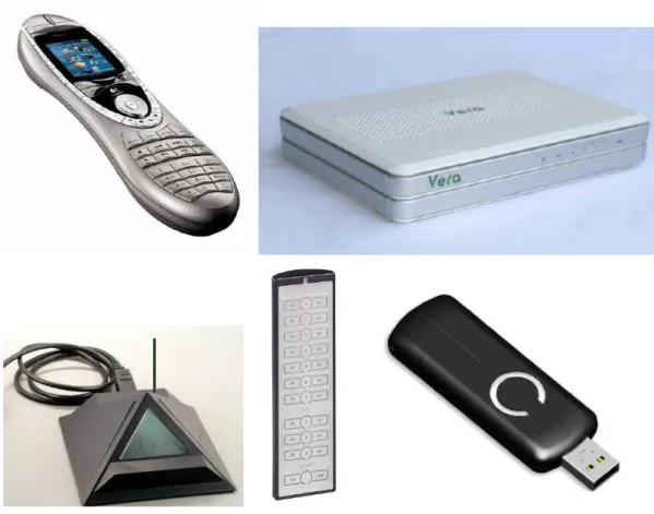
managed automatically. Components include sockets, switches, remote controls, and the Z-Wave Internet Gateway VERA where you can create scenes, events and timer settings to personalise your electrical appliances as you would your home. In terms of pricing
Z-Wave products ranges above proprietary solutions of some
Zigbee or Enocean.
1. Reliability of communication: yes 2. Security of communication: yes 3. Low radio emission: yes
4. Simple usage: yes 5. Low price: not yet
6. Protection of investment: yes 7. Interoperability: yes
1.3 History and Characteristics of Z-Wave
Z-Wave is a development of the Danish company of Zen-Sys. Two Danish engineers founded Zen-Sys at the end of the nineties of the last century. From the initial idea of developing their own home automation solution the company soon evolved into becoming a chip provider selling a home automation ASIC together with own firmware to other manufacturers. This formed an ecosystem of manufacturers with compatible products.
Figure 1.1: 3rd Generation Zen-Sys Chip
The first generation of Zensys hardware was sold from 2003 - at that time still as a combination of a standard microcontroller (Atmel) and a radio transceiver. This hardware platform was extended during the following years with the chip generations 100 (2003), 200 (2005), 300 (2007) and last 400 (2009).
Zen-Sys found the first big customers in the USA where - thanks to X10 – a relevant market and market awareness already existed for home automation.
The first larger Z-Wave device manufacturer in Europe was the German switch manufacturer Merten (now a part of Schneider
Electric), which publicly introduced the Z-Wave based lighting system CONNECT in the end of 2007. Since beginning of 2009 the market dynamics has strongly increased in Europe and Z-Wave also gets more and more adopters in Asia. This is also fostered by the takeover of Zen-Sys by the Asian-influenced chip manufacturer Sigma Designs. Sigma bought the venture capital funded Zen-Sys – among other funded by Intel Ventures - in December 2008.
Figure 1.2: Z-Wave Alliance Website (as of 2009)
One other landmark of the Z-Wave development was the foundation of the Z-Wave Alliance in 2005. In this industrial alliance the
manufacturers of Z-Wave compatible products are gathered. The alliance had more than 200 manufacturers in the end of 2009. The
Z-Wave alliance enhances the standard and also takes care of central marketing events such trade shows. Another central duty of the Z-Wave alliance is the maintenance of the interoperability of the devices on the basis of the Z Wave protocol. This is guaranteed by a
certification program, which results in a logo on the device guaranteeing the compliance to the Z-Wave protocol.
Figure 1.3: Z-Wave Compatibility Program
While all manufacturers base their products on the hardware of Zen-Sys, they have some freedom to implement application.
Zen-Sys defines the radio level with the line encodings and also defines the functions to organize the network itself. Precompiled firmware libraries accomplish this. The manufacturers cannot change them. Z-Wave also defines application specific functions (e.g. switch A is switched when button B is pressed) but the manufacturers are responsible to implement this. Most manufacturers optimize and enhance functions on application layer.
Hence, the certification tests concentrate to make sure that the application layer functions of the device comply with the standard to allow and guarantee interoperability across functionality and
manufacturers boundaries.
1.4 General Layer Model of wireless communication
Wireless systems are complex and consist of a huge number offunctions. As you have already read, there are numerous routes to choose from, but importantly, whatever you choose, has to be
compatible with the products you are using. To help manage the huge number of functions, its useful to split them into different layers. The lowest layer is always used for communication media. In the case of a wireless protocol, this is the air. The highest layer is always the user, in this case, a human being. In case of Z-Wave a three-layer structure has turned out to be useful.
1. Radio Layer: This layer defines the way; a signal is exchanged between a transmitter and a receiver. This includes issues like frequency, encoding, hardware access, etc.
2. Network Layer: This layer defines how real control data are exchanged between two communication partners. This includes issues like addressing, network organization, routing, etc. 3. Application Layer: This layer defines which messages need to
be exchanged to specific applications such as switching a light or increasing the temperature of a heating device.
Figure 1.4: General model of an communication architecture
The following chapters describe the architecture and the necessary user's knowledge of the three communication layers radio, network and application.
2 Radio Layer
2.1 Wireless Basics
Z-Wave uses radio waves, and in comparison to other similar systems, proves to be stronger and more reliable.
In an ideal situation, radio waves spread out steadily like light waves in all directions, generating a spherical field. For technical
applications the wavelength and the frequency are related to each other with the formula:
λ = c / f
In contrast to infrared light, or light waves in general, radio waves can penetrate in ceilings, walls, pieces, of furniture and other objects. Such obstacles however weaken the radio signal and reduce the range.
Figure 2.1: Attenuation of radio signals on a wall
Ideally, if you are going to install wireless components, the less obstacles there are the more effective it will be. In practise, this
means that wireless components should not be installed in random places.
Z-Wave uses the so-called ISM Band in Europe (Industrial-Scientific-Medical) that is open for various industrial and scientific applications. The frequency is 868.42 MHz that results in a wavelength of about 34cm.
Devices can use this band free of further certification and permits; however the maximum transmitting power and transmission time is limited. The transmission time is in Milli Watts and transmitters have to strictly regulate the maximum airtime to minimise interferences. Sending a permanent carrier signal is strictly forbidden.
Transceivers using the ISM band are permitted in most European Countries that have signed the CEPT agreement. Countries like UK, Germany, Netherlands, and even the Middle East have adopted the CEPT regulations into their national wireless band control scheme.
Figure 2.2: Members of the CEPT-Accord in Europe
2.1.1 Wireless Distance Estimations
When planning your wireless network, there are various aspects you need to consider. As with most installations, it s all in the planning. The fitting is relatively easy after that.
The general basics to consider are as follows: • Distance to disturbance sources;
• Effective wall thicknesses;
• Pay attention to shielding materials;
• Attenuation by building materials and furnishings;
with a negative calculation result if necessary to check whether the radio transmission will function thanks to reflexions.
ATTENUATION
The main thing to consider is the wireless distance between the transmitter and receiver. This distance needs to be shorter than the maximum distance of the technical device s parameter (50m or 100m). Then every possible obstacle is determined between the transmitter and the receiver.
The table overleaf can determine the total attenuation of the radio signal.
Here are some aspects explained... Obstacle Former
distance
Type Attenuation New distance
No 1 30 m Concrete 30% 21 m
<< Take new value to next step <<
No 2 21 m Glass 10 % 18,90 m
<< Take new value to next step <<
No 3 18,9 m Plaster wall 10 % 17 m
<< Take new value to next step <<
… 17 m … … …
Figure 2.3: Work Sheet to determine the max wireless distance
If the radio signal penetrates the obstacle at a different angle (more than 90 degrees), then the attenuation effect will be increased. If the range resulting in the end is bigger than the measured distance between transmitter and receiver, the components should function well.
Pieces of furniture, installation of radio components, metal coatings, plantings and high air humidity should all be considered when planning the best route for your wireless system. Because these attenuations are approximate, a test is recommended before the fixed installation is made.
Nr. Material Thickness Attenuation
1 Wood < 30 cm 10 %
2 Plaster < 10 cm 10 %
3 Glass (without metal coating) < 5 cm 10 %
4 Stone < 30 cm 30 %
5 Pumice < 30 cm 10 %
6 Aerated concrete stone < 30 cm 20 %
7 Red brick < 30 cm 35 %
8 Iron-reinforced concrete < 30 cm 30 ...90 %
9 … Ceiling < 30 cm 70 %
10 ... Outer wall < 30 cm 60 %
11 ... Inner wall < 30 cm 40 %
12 Metal grid < 1 mm 90 %
13 Aluminium coating < 1 mm 100 %
Table 2.1: Attenuation by building materials
2.1.2 Distances to other wireless signal sources
Radio receivers should be attached in a distance of minimum 50 cm from other radio sources. Examples of radio sources are:
• Computers;
• Electronic transformers;
• Audio equipments and video equipment; • Pre-coupling devices for fluorescent lamps.
The distance to other wireless transmitters like cordless phones or audio radio transmissions should be least 3 metres. As well as this, the following radio sources should be taken into account:
• Disturbances by switch of electric motors;
• Interferences by defective electrical appliances; • Disturbances by HF welding apparatuses;
• Medical treatment devices.
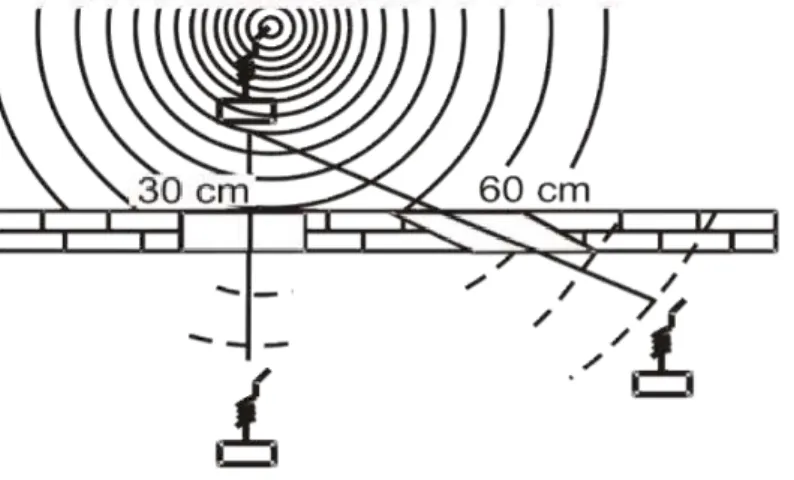
2.1.3 Effective thickness of walls
The locations of transmitter and receiver should be selected in such a way that the direct connecting line only runs on a very short distance through material, which causes attenuation.
Metallic parts of the building or pieces of furniture shield the
electromagnetic waves. Behind a structure like this, there may be a so-called radio shadow, where no direct reception is possible.
Figure 2.4: Effective wall thickness
2.1.4 Wireless Shadows
Metallic parts of the building or pieces of furniture shield the
electromagnetic waves. Behind a structure like this, there may be a so-called radio shadow, where no direct reception is possible.
Figure 2.5: Radio shadow by metallic structures
Despite radio shadow, it is possible for wireless signals to be reflected by metal structures and still reach the final destination. Reflections are unpredictable and it is recommended that you test your systems until you create a more permanent fixing.
2.1.5 Reflexions
Reflexions are used by amateur radio connections to bridge big distances (several thousand kilometres with relatively low power) in the short wave band. On this occasion, the reflective property of the ionosphere is used.
Within buildings reflections may cause disturbances or attenuation if the original and the reflected way are received together.
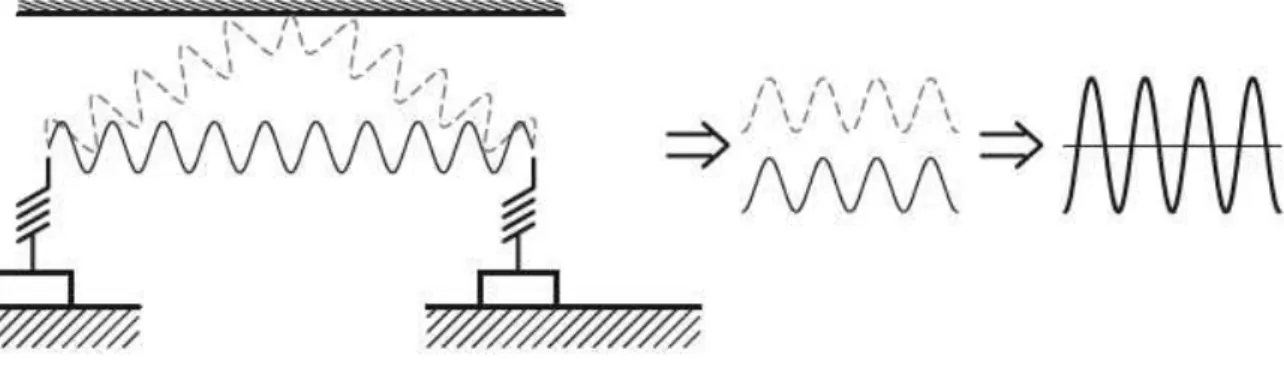
2.1.6 Interferences
Interference can occur in different phase situations that are caused by different run times and by the way the radio waves are increased or attenuated.
Figure 2.7: Signal assuagement by interference
Interference can be resolved by changing the positions of the transmitter or receiver slightly. Even a couple of centimetres may work. It really is a process of trial and error to see what works for you in your home. 2.1.7 Relevance of Mounting heights
If motion detectors are mounted outside the house, the assembly height is critical. If the motion detector is mounted next to a floor or ceiling level, then the radio signal has to penetrate the concrete of the floor/ceiling. This will be ineffective as this will result in very high attenuation of the signal.
2.1.8 General Basics of Installation
The following basic rules should be considered in every planning of a wireless control system:
• Distance to disturbance sources, • Effective wall thicknesses,
• Pay attention to shielding materials,
• Attenuation by building materials and furnishings,
• With a negative calculation result if necessary to check whether the radio transmission will function thanks to reflexions.
2.1.9 EME and Biology
From infrared, to Bluetooth, to Z-Wave, there are numerous wireless messages flying through the air. Its bound to be a concern whether it can affect users health.
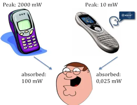
Radiation power from radio transmitters is a critical factor. As most of us use mobile phones, a comparison can be drawn.
Mobile phones transmit a constant radio signal with a peak capacity of 2000 mW into the brain. Without any other protection and mostly it s operated next to your ear, a human will consume about 100 mW into their head. This exposure continues throughout the whole telephone call!
Z-Wave is nowhere near as much of a threat, as mobile phones. The system works with peak transmission power, of a maximum of 10mW at a short time. This corresponds to an average radiation power of only 1mW. This is because neither a radio remote control, radio switch nor a radio transmitter from a motion detector operates directly in or close to the body.
Figure 2.9: Transmitting power of Z-Wave compared to cell phone
The signal attenuation that is generated in a distance of only 1 m causes another reduction of the radiation power around the factor of 40. The human body is only hit by a radiation power of 0.025 mW. This is about 1: 4000 lower than the emission of a mobile phone.
Taking further into account that the radio signal will only be
transmitted during a short period of time when a button is pressed or a sensor signal is transmitted, the electromagnetically emission of a Z-Wave network does not contribute to the general electromagnetic pollution in a home and does not have any negative effect to human beings.
2.2 Z-Wave encoding
Z-Wave uses the ISM frequency band in Europe which is fixed at 868.42 and uses a very robust frequency key modulation (Gaussian Frequency Shift Keying), which allows transmitting data with up to 40 KB/s. Older devices still use 9.6 kb/s so that (for backward
compatibility reasons), all devices also understand a line encoding based on 9.6 KB/s.
The new hardware family Z400, which was introduced in 2009, offers an additional radio, using the frequency of 2.4 GHz
A good antenna for 868 MHz will allow a bridging distance of up to 200 m outdoors. However, inside buildings the maximum distance is limited to 30 m or even below, depending on the structures and the levels of attenuation in the building.
Generally though, all devices use compatible hardware so therefore the details of modulation and line encoding is not of interest to the end user.
3 Network Layer
The network layer is divided into three sub layers:
• Media Access Layer: The MAC layer controls the usage of the wireless hardware. Its functions are invisible for the end user and hence only of little relevance to him.
• Transport Layer: This function makes sure, that a message can be exchanged free of error between two wireless nodes. The end user cannot influence functions of this layer but the results of this layer are visible.
• Routing Layer: This layer makes sure, that – by utilizing other nodes if needed – a message is passed between the original sender and the desired receiver. The functions of the routing layer are visible to the end users and can be optimized by him.
3.1 Media Access Layer and Transport Layer
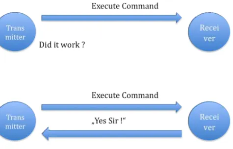
In many wireless communication networks a communication between a sender and a receiver is accomplished by simply sending a message over the air.
In case the message gets lost (due to interference or positioning of the receive too far away from the sender), the sender does not get any feedback, if the message was received and the receiver was able to execute the command properly. This may result in stability problems and frustrate the user of such a network.
In Z-Wave the receiver will acknowledge every command sent by the transmitter. This gives an indication whether the communication was successful or not.
This approach can be compared to the delivery of a letter by
traditional mail service. Not having acknowledged messages is like sending a normal standard letter to a destination. In most of the cases this letter will be delivered correctly and the receiver will be able to
read the letter. However there is no guarantee and some uncertainty remains.
Important messages are therefore to send as “registered letter with return receipt”
Figure 3.1: Communication with and without acknowledgement
Now the sender has a written proof that his letter was delivered correctly and handed over to the receiver.
Even a “registered letter with return receipt” does not guarantee that the letter will always be delivered correctly. However, the sender will get an indication when a receiver has for instance moved out of town and can do other actions to make sure the letter will finally reach its destination.
The return receipt is called Acknowledge (ACK). A Z-Wave transceiver will try up to three times to send a message while waiting for an ACK. After three unsuccessful attempts the Z-Wave transceiver will give up and report a failure message to the user. The number of unsuccessful transmission attempts can be served as an indicator of the quality of wireless connection.
3.2 Z-Wave Network Basics – Inclusion of Nodes
A network consists of at least two nodes that communicate with each other. To be able to communicate with each other, these nodes need to have access to a common media or need to have “something in common”. In most cases this is a physical communication media like a cable. The communication media for radio is the air that is used by all kind of different users. Hence the communication protocol needs to define an identification that allows the different nodes of one network to identify each other and to exclude received messages from unknown or other radio sources.Furthermore every node in a network must have an individual
identification to distinguish him from other nodes within the network.
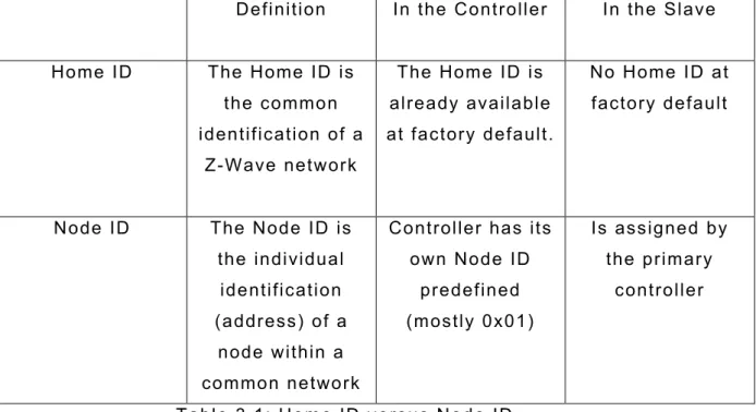
The Z-Wave protocol defines two identifications for the organisation of the network:
• The Home ID is the common identification of all nodes belonging to one logical Z-Wave network. It has a length of 4 bytes = 32 bits and is less of interest for the final user.
• The Node ID is the address of the single node in the network. The Node ID has a length of 1 byte = 8 bits.
As nodes with different Home ID’s can not communicate with each other (this is like they are connected to different cables), they may have a similar Node ID. Within one network, defined by one common home-id it’s not allowed and not possible to have two nodes with identical Node ID.
Z-Wave distinguishes two basic types from devices:
• Controllers are Z-Wave devices that can control other Z-Wave devices,
• Slaves are Z-Wave devices that are controlled by other Z-Wave devices.
Controllers already have their own individual Home ID at factory default. Slaves do not have a Home ID.
Because controllers have already an own Home ID, they can hand over this Home ID to other Wave devices and add them to their own Z-Wave network.
Figure 3.2: Different types of Z-Wave Nodes
Z-Wave controllers exist in different forms: as a remote control, as PC software in conjunction with a Z-Wave transceiver connected in the PC (typically via USB), as a gateway or as a wall switch with special
The Home ID of a controller cannot be changed by the user and
becomes the common Home ID of all devices, which were included by this controller.
Modern Controllers create a random Home ID at every factory reset to avoid problems with re included slave nodes (see chapter 5.4.4 for details)
The controller who begins to build up a network transfers its Home ID to other devices becomes the designated primary controller of this network. In a bigger network several controllers can work together, but there is always only one controller with the privilege to include other controller - the primary controller.
The primary controller includes other nodes into the network by
assigning them his own Home ID. If a node accepts the Home ID of the primary controller this node becomes part of the network. Together with assigning the Home ID the primary controller also assigns an individual Node ID to the new device, which is included. This process is referred to as Inclusion.
Definition In the Controller In the Slave
Home ID The Home ID is the common identification of a
Z-Wave network
The Home ID is already available at factory default.
No Home ID at factory default
Node ID The Node ID is the individual
identification (address) of a
node within a common network
Controller has its own Node ID
predefined (mostly 0x01)
Is assigned by the primary
controller
Table 3.1: Home ID versus Node ID
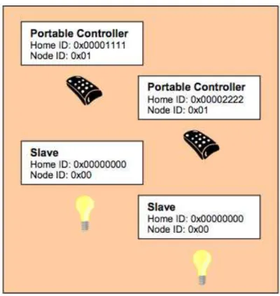
Figure 3.3: Z-Wave devices before inclusion in a network
In Figure 3.3 four devices are available in factory default state. There are two controllers with a preset Home ID. Two other devices cannot operate as a controller (Slave) and, hence, have no own Home ID.
Depending on which of the controllers is used to build up a Z-Wave network, the network Home ID in this example will be either
0x00001111 or 0x00002222.
Both controllers have the same Node ID #1. The slave devices do not have any Node ID assigned. In theory this picture shows two networks with one node in each of them.
Because none of the node in the figure has any common Home ID, no communication can take place.
One of the two controllers is now selected as being the primary
other devices (includes them) and also assigns them individual Node ID.
Figure 3.4: Network after successful Inclusion.
After successful Inclusion all nodes have the same Home ID, i.e. they are connected in a network with each other. At the same time every node has a different individual Node ID. Only with this individual Node ID’s they can be distinguished from each other and can communicate with each other. In a Z-Wave network several nodes having a common Home ID must not have the same Node ID ever.
In the network shown as an example there are two controllers. That controller whose Home ID became the Home ID of all devices is the
primary controller. All other controllers become so called secondary controllers.
A secondary controller is also a controller from the technical point of view and does not differ from the primary controller. However, only the controller with the privilege being the primary controller can include further devices.
Figure 3.5: Two Z-Wave-Network with different Home IDs coexist
Because the nodes of different networks can’t communicate with each other due to the different Home ID, they can coexist and does not even “see” each other.
The 32 bit long Home ID allows to distinguish up to 4 billion (2^32) different Z-Wave to networks with a maximum number of 2^8 = 256 different nodes.
It is not possible that one single node has two different Home IDs or Node IDs. There are devices (so called bridge controllers) that allow bridging two different networks but they consist of two independent Z-Wave nodes with an interconnection of a higher layer. With their individual Z-Wave networks they still appear as a simple node.
Because some addresses of the network are allocated for the internal communication and special functions, maximum 232 different nodes can communicate in a network.
If Z-Wave nodes are deleted from a network, this is called Exclusion in the Z-Wave terminology. During the Exclusion process the Home ID and the Node ID are deleted in the device. The device is moved back in the factory default state (controllers have their own Home ID and slaves do not have any Home ID).
3.3 Meshing and Routing
In a typical wireless network the central controller has a direct wireless connection to all of the other networking nodes. This always requires a direct radio link. In case of disturbances the controller does not have any backup route to reach the nodes.
Figure 3.6: Network without routing
The radio network illustrated above is a non-routed network.
Nodes two, three and four lie within the radio ranges of the controller that is labelled number 1. Node 5 lies beyond the radio range and cannot be reached from the controller.
mechanism to overcome this limitation. Z-Wave nodes can forward and repeat messages that are not in direct range of the controller. This gives greater flexibility as Z-Wave allows communication, even though there is no direct wireless connection or if a connection is temporarily not available, due to some change in the room or building.
Figure 3.7: Z-Wave-Net with routing
Figure 3.7 shows the controller with „Node ID 1” can communicate directly to the nodes 2, 3 and node 4. Node 6 lies outside its radio range, however, it is within the radio range of node 2. Therefore the controller can communicate to node 6 via node 2. This way from the controller via node 2 to node 6 is called a “route”.
Figure 3.7 illustrates another side effect of the routing. In case the direct communication between Node 1 and Node 2 is blocked, but there is still another option to communicate to node 6 via node 2, by using node 3 as another repeater of the signal. It is evident, that more nodes result in more different routing options for the controller and therefore in a more stable network.
Z-Wave is able to route messages via up to four repeating nodes. This is a compromise between the network size and stability, and the
Figure 3.8: Z-Wave communicates „across the corner“
How are these routes built in a Z-Wave network?
Figure 3.9: Maximum distance between two nodes via 4 repeaters
Every node is able to determine which nodes are in its direct wireless range. These nodes are called neighbours. During inclusion and later on request, the node is able to inform the controller about its list of neighbours. Using this information, the controller is able to build a table that has all information about possible communication routes in a network. The user can access the routing table. There are several software solutions, typically called installer tools, which visualise the routing table to optimize the network setup.
Figure 3.10: Example of a meshed network
Figure 3.10 shows an example of a Z-Wave meshed network, with one controller and five other nodes. The controller and is the primary controller with Node ID 1.It can communicate directly with node 2 and 3. There is no direct connection to node 4, 5 and 6. Communication to node 4 works either via node 2 or via node 3.
Figure 3.11 shows the routing table of such a network:
The rows of the table contain the source nodes and the columns contain the destination nodes. A “1” is a cell which indicates that the two nodes are direct neighbours.
Figure 3.12: Routing from Node 1 via Node 3 to Node 4
The example shows the connection between Source Node 1 and
destination Node 4. The cell between Node 1 and 4 is marked “0“. This means the nodes are not neighbours and cannot communicate directly. The route goes via Node 3 that is in direct range both from Node 1 and Node 4.
In the example below Node 6 can only communicate with the rest of the network using Node 5 as repeater. Since the controller does not have a direct connection to Node 5, the controller need to use one of the following routes: 1 -> 3 -> 4 -> 5 -> 6 or 1 -> 2 -> 5 ->6.
Figure 3.14: Routing table example of a meshed network
A controller will always try first to transmit its message directly to the destination. If this is not possible it will use its routing table to find the next best way to the destination. The controller can select up to three alternative routes and will try to send the message via these routes. Only if all three routes fail (the controller does not receive an
acknowledgement from the destination) the controller will report a failure.
3.4 Types of Network Nodes
It was already mentioned that a Z-Wave network consists of two different node types:
• Controller and • Slaves.
A routing slave is a slave with some advanced functions regarding routing capabilities. Slaves are categorized further into standard slaves and routing slaves.
The three different node types have three main capabilities. The main difference between the three node types is their knowledge about the network routing table and subsequently their ability to send messages to the network:
Neighbours Route Possible
functions
Controller Knows all neighbours
Has access to the complete routing
table
Can communicate with every device in the network, if
a route exists.
Slave Knows all
neighbours
Has no information about
the routing table
Can only reply to the node that he has received the message from. Hence, can not send unsolicited
messages Routing Slave Knows all his
neighbours
Has partial knowledge about
the routing table
Can reply to the node that he has
received the message from
and can send unsolicited messages to a
number of predefined nodes he has a route to. Table 3.2: Properties of the Z-Wave device models
From this comparison a number of basic rules arise:
• Controllers can send messages to all node in the network, solicited and unsolicited (“The master can talk whenever he wants and to whom he wants”)
• Slaves can not send unsolicited messages but only answer to requests (“The slave shall only speak is he is asked”)
• Routing Slaves can answer requests and they are allowed to send unsolicited messages to certain nodes the controller has predefined (“The sensor slave is still a slave but - on permission – he may speak up”)
Since the functionality of standard slaves is quite limited, this type of node is only used for dimmers and switches that are installed in a fixed location. Every kind of sensor or any device that can be used on multiple locations must be a routing slave or even a controller.
Typical applications for slaves are:
Slave Fixed installed mains powered
devices like wall switches, wall dimmers or Venetian blind controllers Routing Slave Battery-operated devices and mobile
applicable devices as for example sensors with battery operation, wall plugs for Schuko and plug types, Thermostats and heaters with battery
operation and all other slave applications
Table 3.3 Typical applications for slaves
Establishing, Changing and Destroying a Z-Wave Network
If a device is added to a Z-Wave network (Inclusion), the controller always requests an updated list of neighbouring nodes from these nodes and updates his routing table.
In case another – secondary - controller is included into the network, the including (primary) controller hands over an actual snapshot of his
routing table to the included controller. Right at this moment both controllers have the very same routing table. If more nodes are
included later, the routing table of the primary controller gets updated while the routing table of any secondary controller may still show the old status. These secondary controllers need to be updated manually in such a case.
If nodes are excluded from the network, the corresponding entries in the routing table are deleted. If a secondary controller is excluded from the network this secondary controller will not only delete its old Home ID but also the old routing table which is not longer relevant to him once he left the network.
The routing table in the primary controller always shows the actual status of the network after inclusion of the devices. During normal operation a node can however
- go out of operation (damaged) or - can be moved to a different location.
In both cases the routing table is not longer valid and communication to the moved or damaged node may fail (if the node is just moved its possible that it was moved luckily in direct range of the controller or into a place where his old neighbours still can reach him).
Any failed communication to a node results in an error message. In parallel the controller will mark this node as failed node by putting him into a so called “failed node list”. The failed node list contains nodes with a failed communication. Being in the failed node list does not necessarily mean that node is permanent damaged. Any working communication will move the node back into the original routing table.
If no successful communication happens, the node will stay in the failed node list and can be removed from the network. This will not be done automatically but on user request. Figure 3.15 shows a user dialog to enable to remove a failed node from the network.
Figure 3.15: Screenshot of a Z-Wave Controller with a button to exclude a failed node
The Z-Wave network is furthermore able to determine movements of devices and update the routing table automatically, however certain conditions need to apply for this. Refer to chapter 3.7 for more details.
Slaves:
If a slave is moved into a different location its neighbours are not longer able to reach him for communication. A message from the controller to this slave will therefore fail. The controller can’t
determine if the slave was just moved or is permanently removed or dead. The controller will always treat these nodes as failed and move them to the failed-node-list.
To find a moved node in the network the controller can scan the whole network and ask every known node to update its neighbouring list. If the moved node is still in range of at least one node, this operation will locate the moved node and the controller is able to update its routing table and remove the moved node from the failed-node-list.
Such a network rebuilt will generate a lot of data traffic that is the reason why this is not done automatically through failed node detection.
User can trigger such a network scan on the controller, either by pressing special keys on mobile primary controllers or by using a special dialogs on PC controllers (repair my network).
Figure 3.16: Network Reorganization
The controller will test all connections to its direct neighbours first and scan its neighbourhood for lost devices. In a next step he will ask all known nodes to do the same scan and report back the result.
Figure 3.16 also shows that battery powered devices need a special treatment. Battery powered devices are mostly in an energy savings mode and will only wakeup occasionally. The dialog on Figure 3.16 sets a maximum timeout to wait for any life signal from the battery-operated device during the network scan.
Controller:
Controllers know the whole network topology and can therefore always find a valid route to a communication partner (assuming that the
routing table is correct and updated).
Controllers are distinguished into static or portable controllers. A static controller is supposed to be located on a fixed position in the network and shall not be moved. A static controller is mains powered and can route messages.
A portable controller is supposed to be moved around and is therefore typically battery powered. As a battery powered device the portable controller will sleep most of the time and is therefore not able to route message from other nodes.
If a static controller is moved, a network reorganisation or network scan is required. A portable controller will always try to reach nodes in wireless range. If this fails the controller will try to generate a
temporary routing table to find a routed way to the destination device.
3.5 Challenges in typical network configurations
As a result of the routing functionality there are some typical network configurations with their individual challenges and requirements.
3.5.1 Z-Wave Network with one portable controller
Z-Wave works by starting with a very small network and extending this network later on as and when you need. A very typical small network consists of a remote control and a couple of switches or dimmers. The remote control acts as primary controller and includes and controls the switches and dimmers.
During inclusion the dimmers and switches should be installed at their final location already, to make sure that a correct list of neighbours will be recognised and reported.
A network configuration like this works well as long as the remote control can reach all switches and dimmers directly (the node which is to be controlled is “in range”). In case the controlled node not in
range, the user may experience delays, because the remote control needs to detect the network structure first before controlling the device.
In case a device was included and moved afterwards to a new position, this particular device can only be controlled by the remote control if it is in direct range. Otherwise the communication will fail, because the routing table entry for this particular device is wrong and the remote control is not able to do a network scan at the moment of operation.
3.5.2 Z-Wave Network with one static controller
Another typical network consists of a static controller - mostly PC software plus Z-Wave transceiver as a USB dongle or an IP gateway IP as well as a number of switches and dimmers.
Figure 3.18: Example of a network with one static controller
The static controller is the primary controller, and includes all other devices.
Because a static controller is bound to a certain location, the other Z-Wave devices must be included while being in direct range with the static controller. They will typically be installed at their final location after inclusion.
3.5.3 Networks with multiple controllers
In a larger network several controllers will work together. A static controller – e.g. a PC – is used for the configuration and management of the system and one or several remote controls carry out certain functions in different places.
Figure 3.19: Z-Wave Network with multiple controllers
If a network has multiple controllers, the user needs to determine which of the controllers will be the primary controller.
Inclusion of a static controller is a challenge, if the devices need to be moved to their final location afterwards. A network re-organisation needs to be performed.
Static controllers are usually more reliable and cannot get lost easily. They typically offer backup functions to replace the hardware in case of severe damages.
Network with static controller as a primary controller:
Inclusion on a static controller is a challenge if the devices need to be moved to their final location afterwards – a network reorganisation need to be performed.
Static controllers are usually more reliable and cannot get lost so fast. They typically offer backup functions to replace the hardware in case of severe damages.
Network with portable controller as a primary controller:
Remote controls are more vulnerable to damage and loss. Usually remote controls do not offer a backup function. If the primary
controller was damaged or lost, a complete re-inclusion of the whole network would need to be performed. However, devices can be
included after they were installed, which results in a much more stable network, and no need for network re-organisation.
The choice of the primary controller - static or portable - depends more on the personal preference of the user than on technical necessity.
Nevertheless, a basic problem in networks with several controllers is the synchronization of the routing tables of the different controllers. The primary controller passes a snapshot of the routing table to every included secondary controller at the moment of inclusion. At this moment and only at this moment the two routing tables are equal. Any inclusion or exclusion of further devices will results in different routing tables of the secondary and the primary controller. These results in a failure if the secondary controller will communicate with a device that is not longer included in the network. Furthermore the secondary controllers with outdated routing tables can’t communicate with the device included after they were included in the network.
There are two approaches to minimize this problem.
1. Secondary controllers are always integrated into the network last. They will then receive a more or less correct routing table. 2. After inclusion of new devices all secondary controllers will be
reincluded to update the routing table. This is a lot of work and not user friendly.
If several portable controllers exist in a network, it is practically nearly impossible to keep an updated routing table in all controllers.
A solution to this problem is offered in additional functionality of static controllers in the network – SUC and SIS.
3.6 Static Update Controller (SUC) and SUC ID Server
(SIS)
If there is one primary controller in the network, it will hand over its routing table, to every secondary controller included. After the next inclusion or exclusion of a device, by the primary controller the routing tables of all secondary controllers become invalid. To make sure that there is at least one updated and valid routing table only, the primary controller shall have the privilege to include/exclude devices. For a secondary controller it is always possible to request an update of his routing table.
The re quireme nt for a user fr iendly a nd stable ne twork is, tha t :
• Every battery operated mobile controller shall be able to include devices.
• The routing tables of all controllers in the network are kept consistent and an update shall allow every controller to control every device in the network.
This goal is accomplished by activating a SUC /SIS controller in the network.
3.6.1 Static Update-Controller (SUC)
The Static update controller (SUC) is a special function of a static controller. Most static controllers (a controller with fixed location and powered by mains) can perform as an SUC. However, the function typically needs to be activated first.
The SUC receives the updated routing table from the primary
controller and offers this routing table to all other controllers in the network. Because the SUC is a static controller and therefore always active in the network, any other controller can frequently request an updated routing table from the SUC.
To make sure that all other nodes and particularly other controllers are aware of the presence of a SUC in the network, the Node ID of an activated SUC is communicated within the network periodically.
Figure 3.21: SUC in a Z-Wave Network
Having an active SUC in the network allows you to keep the primary controller role on a portable controller. Every change of the network caused by inclusion or exclusion of a node by the primary controller will be reported to the SUC and is then available to all other
controllers, even if the primary controller is not active.
Figure 3.22: Update of the Routing table in a SUC
Since most of the controllers are battery operated and therefore not active all the time, these controllers have to request an updated routing table periodically or at least when woken up, by pressing a
button. To perform this task the mobile battery operated controllers need to be informed about the presence of a SUC in the network. If the original – mobile – battery operated primary controller is lost or damaged, the SUC can assign the primary privilege to a new mobile controller, protecting the user from re-establishing the whole network with a brand new primary controller, and having a different Home ID.
3.6.2 Static ID Server (SIS)
Even a SUC in the system does not solve the problem that only one controller has the primary privilege and can include new device. This limitation is overcome by enhancing the SUC functionality by another function called SIS = Static ID Server.
The SI S ac ts a s depot for new No de I D s w hich c an be as s igned by mobile contro ller s . Having a n SI S pre sent in the networ k allow s e very co ntroller in the ne twor k to include a fur ther device. The co ntro ller w ill jus t re quest a new node I D from the SIS a nd a ss ign this new Node I D to the ser ver. W ith the SI S it is made s ure tha t no two no des ge t as signed the sa me no de ID. The o nly requireme nt is a mobile contro ller nee ds to fulfil in order to include new device s, is tha t it has a ne twork c onne ctio n to the SI S server to re ques t a node ID.
Figure 3.23: SIS Server in a Z-Wave-Network
This kind of configuration with server SIS has the following advantages and disadvantages:
Advantages:
• The actual network topology and the information about all nodes are saved in a static controller and are therefore better
protected than within a mobile battery powered device. • All controllers in a network can integrate new devices.
• The network configuration and handling becomes very flexible.
Disadvantages:
• Function is available only from the firmware version 3.40. It is possible that there are some devices in the network with older firmware that do not support this configuration.
• Inclusion controller can integrate only devices if it has a wireless connection to the SIS.
• With the SIS there exists a "Single Point of Failure". A damaged SIS result in a complete new network setup.
Since the SUC/SIS functionality is already included in the firmware of most modern static controller, or a USB dongle, most Z-Wave networks can take advantage of these functions if a static controller is present. However, this function needs to be activated.
A static controller can also be a primary controller, as well as have SUC/SIS functionality. This configuration is typical in real networks.
Figure 3.24: Controller rules shown in a Gateway User Interface
3.7 Networks with portable slaves
It was already described how a Z Wave network can handle a changing position of controllers or slaves. If slaves or static controllers are changed in their physical position, a new organisation of the whole network must be performed afterwards.
Get Lost
If an SUC controller is present in the network it is able to determine a new position of a slave and update the networks routing table
accordingly. The procedure to achieve this is called in Z-Wave terms “Get Lost –Algorithm” and only works for routing slaves.
A normal slave is not allowed to send unsolicited messages and can therefore never determine any change of its position in the network, since no unsolicited message can fail. Routing slaves however have this ability.
If the sending of an unsolicited message from a routing slave fails, this routing slave will conclude that its routing table is not longer valid.
Figure 3.25: Routing-Slave realizes movement
As a first step this node will send out a broadcasting message to anybody with a “cry for help” message. A node that received an unsolicited “cry of help” message knows that the sender of this
message has found itself in a new location. This node, however, is not possible to help the crying node with an updated routing table. If this node is also a routing slave and does have routing information about how to reach the SUC in the network, it will forward the “cry for help” message to the SUC.
Figure 3.26: Routing-Slave cries for help
The SUC can update its own routing table and assign new routes to the crying node by performing the same steps he would do when
including the device. The “cry for help” message is able to auto-heal a network in case a node has been moved.
In order to have a working auto-healing function within the network, the following requirements need to be fulfilled:
1. A SUC need to be present in the network
2. The moved nodes must be a routing slave not a standard slave. 3. In the new position there must be at least one routing slave in
range.
4. The moved node must detect that he was moved. This is only possible if this node sends out an unsolicited message.
3.8 Inclusion and Exclusion in practise
This section describes how inclusion and exclusion of nodes works in practical terms.
3.8.1 Inclusion and Exclusion of Slaves
(1) Inclusion of nodes is always started by the primary controller (or any controller in case a SIS controller is present). The including
controller must be turned into a so-called inclusion mode. This is done either by pressing a special key or a special key sequence or by
turning a Z-Wave USB stick into the inclusion mode using control software on a PC.
Figure 3.29: Example of Inclusion Function in PC software
(2) Once the controller is in the inclusion mode each node to be included need to confirm inclusion by performing a local action, typically pressing a button. All Z-Wave devices will have at least one button to confirm the inclusion. This may be a function button of the device, a dedicated inclusion button or simply an anti-tampering switch.
(3) The number of times the button needs to be pressed depends on the product and the vendor. Vendors either choose a single click or a triple click as confirmation sequence. To unify the user experience it is meanwhile recommended to use the triple press action for
confirmation. Since the triple press always also performs a single press and two more single presses does not harm, it is recommended to always do a triple press.
The single or triple press of a button causes the node to issue an information packet, in Z-Wave terminology called node information frame, with its current Node ID and Home ID.
(4) If a controller in the inclusion-mode receives a node information frame it will check this frame. If there is no Home ID given, this frame will be included into the network by assigning a Node ID and the Home ID of the controller. This action is typically confirmed with a LED
blinking or other useful form of user feedback. Otherwise the Information frame will be simply ignored.
Figure 3.30: Example of a manual describing of the inclusion process
Figure 3.30 shows the manual section of a manufacturer about his Z-Wave products and the inclusion process. By pressing “INCL" on the controller here at an schematically displayed remote control – this device is moved into the Inclusion mode. The triple press on a button of a Z-Wave device gives a confirmation for the inclusion.
This process leads to the following conclusions:
(1) Only a controller can include new devices
(2) Its only possible to include a node which was not already included into a different network
(3) There is always a physical interaction needed at the device that is to include. This makes sure that no device is included against the will of the physical owner of the device. Having physical access to the device is defined an ownership in this regard.
In case a node shall be integrated into a new network that was already included in a different network this nodes must be detached from the previous network first. This process is called “Exclusion” and is performed the same way as the inclusion.
(1) The excluding controller must be turned into an exclusion mode. This is done either by pressing a special key or a special key sequence or by turning a Z-Wave USB stick into the exclusion mode using a control software on a PC.
(2) The node to be excluded has to send out a node information frame. Either single or triple press of a button on the device triggers this.
(3) If the excluding controller receives a node information frame from a node which contains a valid Home ID the controller will send this node a reset message to delete the Home ID and turn the node back into factory default status. If no valid Home ID is received which means that the sending nodes is not part of a network the process is terminated without any further action. (4) Its possible to exclude multiple devices after another. As long
as the controller is in the exclusion mode devices can be
excluded. A special key sequence or pressing the exclusion key again typically terminates the exclusion mode.
Any Z-Wave controller regardless of its inclusion in the same network can perform the exclusion of a device. This is required to make sure that nodes from a network with damaged controllers can still be reused in a different network. However, a local interaction like pressing a button is required to proof the ownership of the node.
Figure 3.31: Example from a user’s manual describing the exclusion process
Within a Z-Wave device the exclusion leads to a full reset of all functions and settings back to factory default