A pattern based approach to defining the dynamic
infrastructure of UML 2.0.
APPUKUTTAN, Biju K, CLARK, Anthony <http://orcid.org/0000-0003-3167-0739>, EVANS, Andy, MASKERI, Girish, SAMMUT, Paul, TRATT, Laurence and WILLANS, James
Available from Sheffield Hallam University Research Archive (SHURA) at:
http://shura.shu.ac.uk/11898/
This document is the author deposited version. You are advised to consult the publisher's version if you wish to cite from it.
Published version
APPUKUTTAN, Biju K, CLARK, Anthony, EVANS, Andy, MASKERI, Girish,
SAMMUT, Paul, TRATT, Laurence and WILLANS, James (2002). A pattern based approach to defining the dynamic infrastructure of UML 2.0. In: Fourth Workshop on Rigorous Object Oriented Methods, University College, London, March 2002. N/A.
Copyright and re-use policy
A pattern based approach to defining the dynamic
infrastructure of UML 2.0
Biju K. Appukuttan1, Tony Clark2, Andy Evans3, Girish Maskeri4, Paul Sammut3, Laurence Tratt2 and James S. Willans3
Abstract. The 2U Consortium has recently submitted a proposal for the definition of the UML 2.0
infrastructure. This uses an innovative technique of rapidly “stamping out” the definition using a small number of patterns commonly found in software architecture. The patterns, their instantiation, and any further language details are described using precise class diagrams and OCL, this enables the definition to be easily understood. The main focus of the 2U approach is on the static part of the definition. A further concern when modelling software, using languages such as the UML, is describing the dynamic behaviour of the system over time. The contribution of this paper is to provide a template that can be used to “stamp out” the dynamic part of the UML 2.0 infrastructure. We argue for the suitability of the dynamic template because it makes little commitment to concrete abstractions and can, therefore, be used to support a broad spectrum of behavioural languages.
1. Introduction
The power of designing software independent of an implementation has become well established in recent years with the development of modelling notations such as the Unified Modelling Language (UML) [1]. The UML enables the designer of a system to reify requirement-oriented descriptions of a system to an implementation through a number of models. Consequently there can be increased certainty that the implementation accurately reflects the requirements. Despite this, the lack of precision within the current version of the UML semantics can compromise this certainty and result in a flawed implementation. This need for precision has been recognised by the Object Management Group’s requests for proposals (RFPs) for the next major revision of UML (version 2.0). The RFPs require that a precise infrastructure be defined for UML 2.0. The intention is that all UML modelling notations will be built upon the infrastructure such that there can be no ambiguity concerning the meaning of the notations and their relationship to each other.
Work by the 2U consortium has been successful in developing an unambiguous infrastructure model for UML [2]. A novel part of this submission has been the use of patterns to generate the definition. Patterns help in promoting reuse as well as reducing the complexity of the modelling activity. However, the consortium has mainly focused on the static aspects of the submission. Clearly, a further concern when defining UML is the ability to model runtime behaviour. This should provide the ability to capture the complete behaviour of the system. The static definition may then be viewed as a snapshot (view of the state of the system at a given instant of time) of the dynamic behaviour. The ability to capture dynamic behaviour provides a number of desirable benefits:
N Execution modelling capability N Simulation of execution
N Code generation capabilities N Additional validation capability
1. Department of Computer Science, King’s College, London, England. (On deputation from Tata Consultancy Services, India.) [email protected]
2. Department of Computer Science, King’s College, London, England. {anclark | laurie}@dcs.kcl.ac.uk 3. Department of Computer Science, University of York, York, England. {andye | pauls | jwillans}@cs.york.ac.uk
N Possibility of further tool support
The contribution of this paper is to extend the 2U approach of defining the static component of languages using patterns, to the dynamic component. This is achieved by introducing a pattern for dynamic behaviour and using this to “stamp out” the dynamic component of the infrastructure.
2. Describing behaviour
In order for a modelling infrastructure to be useful, it must anticipate and accommodate features of models that are likely to be contained in the super structure. Numerous existing UML dynamic models exist such as use-case diagrams, sequence diagrams and Statecharts [3]. These models describe how actions (often called events) transform the state of the system being specified. This characteristic is common to all behavioural modelling notations including more formal notations such as CSP [4] and Petri-nets [5]. Consequently, behavioural models can be equivalently represented by (being reduced to) a set of ordered actions that are linked to descriptions of the system before and after each action is applied (pre and post states). What cannot be commonly factored from behavioural models is the granularity of abstraction with which actions and system states are described. For instance within a use case model, an action might be “close file” where the pre condition is “file saved” and the post condition is “file closed”. The same action might be described as “let file = null” in a state diagram with “isSaved (file)” as the pre condition and “file == null” as the post condition.
Therefore, the lowest common denominator in describing behaviour is the notion of actions transforming the state of the system. However, it is necessary to be able to describe this without committing to particular action and system state abstractions.
3. The 2U approach
The 2U approach to defining UML 2.0 infrastructure combines a number of strategies [2]. In this section we discuss these strategies and demonstrate them using examples. These examples will be later utilised in the definition of a template for dynamic behaviour.
3.1 Underlying philosophy
Separation of syntax and semantics
The syntax of models and their semantics are described as distinct entities related by a mapping (semantic mapping). In the infra structure definition, the syntax is described as abstract, the abstract syntax will be mapped to a concrete syntax within the super structure (i.e. boxes and lines).
Modular development approach
Reuse of language patterns
It is generally considered that good software architectures exhibit recurring structural patterns [6]. The 2U approach identifies common patterns, and encapsulates these into building blocks that can be rapidly reused. The use of patterns also makes the process of building languages less complex and error prone because they describe (partial) solutions that are known to work.
3.2 Technology used to support the 2U methodology
Templates
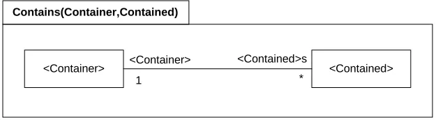
The patterns identified are encapsulated into a reusable form called package templates. Templates can be instantiated with particular data abstractions. Templates, the instantiation of templates, and non-template language definition are described using the meta-modelling language (MML) [2] that has a visual and textual form. The visual form is described using class diagrams and OCL constraints. Illustrated in figure 1 is the template for the container package (taken from [2]). Shown in figure 2 (taken from [2]) is the template for a package that maps syntax to semantics definitions. Both these templates have no OCL constraints.
<Container> <Container> <Contained>s <Contained>
1 *
Contains(Container,Contained)
Figure 1: Container template
<Model Element> <Instance Element>
<Model Element> <Instance Element> AbstractSyntax SemanticDomain
SemanticMapping
[image:4.595.146.460.379.465.2]Semantics(ModelElement,InstanceElement)
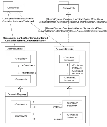
[image:4.595.135.461.481.722.2]Templates can also be used for “stamping out” new templates. An example of this can be seen in figure 3 (taken from [2]) where the Contains template package (figure 1) and the semantics template package (figure 2) have been used multiple times to define the syntax, semantics and semantic mapping of a contains package. The dotted arcs linking the templates describe how parameters are substituted during the “stamping out” process to arrive at new languages.
The textual form of MML can be used in conjunction with the meta-modelling tool (MMT) in order to build models and ensure that models satisfy constraints.
<Container>
<Container> <Container Instance> AbstractSyntax SemanticDomain
SemanticMapping
ContainerSemantics(Container,Contained, ContainerInstance,ContainedInstance)
<Contained> <Container>
<Contained>s 1
*
<Contained Instance>
<Contained Instance>
<Container Instance> <Contained Instance>s 1
<Contained> <Contained Instance> of instance
1 *
of instance
1 *
Container() Semantics()
[<ContainerInstance>/Container,
<ContainedInstance>/Contained] SemanticDomain,<ContainerInstance>/SemanticDomain.InstanceClass][AbstractSyntax,<Container>/AbstractSyntax.ModelClass,
[AbstractSyntax,<Contained>/AbstractSyntax.ModelClass, SemanticDomain,<ContainedInstance>/SemanticDomain.InstanceClass]
*
InstanceContentsCommute:
context class <ContainerInstance> inv:
[image:5.595.118.490.193.632.2]self.of.<Contained>s = self.<ContainedInstance>s -> iterate(element S = Set{} | S->union(Set{element.of}))
4. Behavioural template
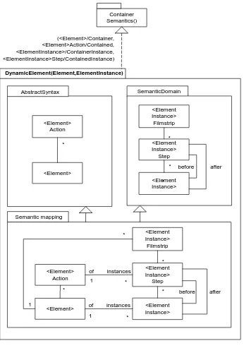
A template for describing behaviour is shown in figure 4 “stamped out” using the container semantics template (figure 3), the textual form of this template (parsed and verified by MMT) is given in appendix A (note that the template is incomplete in terms of constraints). The template addresses the issues highlighted in the section 2 by characterising an understanding of behaviour as some action (<Element>Action) causing a transformation (<ElementInstance>Step) described as a pre system state and a post state (<Element Instance>) without being concrete about what these might be. Furthermore, the template captures an understanding of collections of transformations as forming valid executions (or traces) of the system (<ElementInstance>Filmstrip).
Container Semantics()
<Element> Action
<Element>
<Element Instance> Filmstrip
<Element Instance> Step
<Element Instance>
before after *
*
* 1
1
1 of
of
instances instances
DynamicElement(Element,ElementInstance)
(<Element>/Container, <Element>Action/Contained, <ElementInstance>/ContainerInstance, <ElementInstance>Step/ContainedInstance)
Semantic mapping
<Element Instance> Filmstrip
<Element Instance> Step
<Element Instance>
before after
* <Element>
Action
<Element>
SemanticDomain AbstractSyntax
* * * *
*
[image:6.595.130.476.244.737.2]*
Illustrated in figure 5 is the dynamic template instantiated for a class and object.
Class_ Action
Class
Object_Filmstrip
Object_Step
Object
before after *
*
* 1
1
1 of
of
instances instances
DynamicElement(Class_,Object_)
Semantic mapping
Object_Filmstrip
Object_Step
Object
before
* Class_ Action
Class_
SemanticDomain AbstractSyntax
* * * *
after
*
Figure 5: Dynamic element template instantiated for Class/Object
5. Example
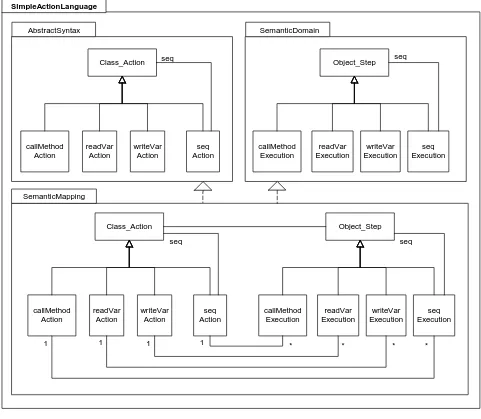
Illustrated in figure 6 is a trivial action semantics which extends the dynamic template with five actions: callMethod, readVar, writeVar and seq2. The final action supports the sequential execution of the other three actions.
Class_Action
callMethod Action
readVar Action
writeVar Action
seq Action
Object_Step
callMethod Execution
readVar Execution
writeVar Execution
seq Execution
Object_Step
callMethod Execution
readVar Execution
writeVar Execution
seq Execution Class_Action
callMethod Action
readVar Action
writeVar Action
seq Action
1 *
1 1 1 * * *
SemanticDomain AbstractSyntax
SemanticMapping SimpleActionLanguage
seq seq
seq seq
validExecutions:
context class callMethodExecution inv:
self.pre == self.post // does not change the state of the system context class readVarExecution inv:
self.pre != self.post // does change the state of the system context class writeVarExecution
self.pre != self.post // does change the state of the system context class seqExecution
actionSequence->forall(i | i.pre == actionSequence.head() || i.pre == actionSequence.at(actionSequence.count(i)-1).post)
// all sequenced actions are either the first action (head) or their pre condition is equal to the preceding indexed action’s post condition
[image:8.595.57.538.144.563.2]
Figure 6: A simple action semantics
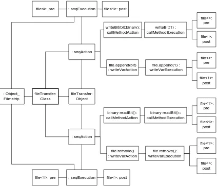
In order to illustrate the use of the action semantics we demonstrate its use in modelling the trivial binary file transfer program shown in figure 7. The program enables bits to be written to a sequence (file) by a writeBit method, and bits to be read (and removed) from a sequence using a
readBit method.
class fileTransfer {
file : seq
writeBit(bit:binary) {
file.append(bit) }
binary readBit() {
return file.remove() }
}
Figure 7: A binary file transfer program
fileTransfer: Class
fileTransfer: Object : seqAction
: seqExecution file<1>: post file<>: pre
writeBit(bit:binary): callMethodAction
file.append(bit) : writeVarAction
file<>: pre
file<>: post
file<>: pre
file<1>: post writeBit(1) :
callMethodExecution
file.append(1) : writeVarExecution
: seqAction
: seqExecution file<>: post file<1>: pre
binary readBit(): callMethodAction
file.remove() : writeVarAction
file<1>: pre
file<1>: post
file<1>: pre
file<>: post binary readBit()::
callMethodExecution
file.remove(): writeVarExecution : Object_
[image:9.595.210.355.154.298.2] [image:9.595.90.513.374.738.2]Shown in figure 8 is a model of the file transfer program described using the action extensions (figure 6) to the dynamic template. The object filmstrip describes that the write and read steps can be executed in sequence. The filmstrip represents the states of the file as the steps are executed. In the example shown, the write action is executed first resulting in a bit being added to the file. The write action is further subdivided into a writeBit action followed by a file append action. The write action results in a bit being added to the file. Similarly the read action has a readBit followed by a remove action which removes the bit that was read previously. Thus the execution of the read action results in a bit being removed from the file.
Because we have not defined a concrete syntax for the simple action semantics, the model shown in figure 7 is particularly verbose even for this simple example. Furthermore, for clarity of presentation, we have omitted some of the associations describing how a file transfer class owns all its actions, and the instance of that class (example) owns all its steps. However, this example does serve to illustrate the flexibility of the proposed dynamic semantics template and its use in associated with a less abstract action semantics. Using the MMT tool we are able to ensure that behaviours defined in this model are valid executions (i.e. that the action semantics OCL constraints of figure 7 hold for the model).
6. Discussion
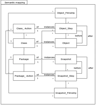
The major strength of the dynamic template described in the previous section is that it can be “stamped out” using any data abstractions. When the template is stamped out on a contained element (i.e. packages) and a container element (i.e. classes), there is coherency between behaviours actions executed at the contained and container level. An example of the dynamic template “stamped out” for packages and classes is shown in figure 9 (although only the semantic domain).
In the previous section we illustrated the use of the dynamic template using a simple action language. The template is intended to be generic such that many different action languages can be built upon it. For instance, there will be an action language to support state machines and a different language to support sequence diagrams. This contrasts with other approaches to dynamic behaviour definition (such as [7-10]) that attempt to define a single action language to support all behaviours. Such approaches result in an action language that is verbose and unwieldy and may not be able to support all behavioural modelling languages.
Class_ Action
Class
Object_Filmstrip
Object_Step
Object
before after *
*
*
* 1
1
1 of
of
instances instances Semantic mapping
* *
Package_ Action Package
Snapshot_Filmstrip Snapshot_Step
Snapshot
before after
*
* * 1
1 1
of of
instances instances
* *
*
[image:11.595.134.451.77.422.2]*
Figure 9: The dynamic template “stamped out” for packages and classes
8. Future work
The example of figure 8 aptly demonstrates the complexity of defining models using abstract, rather than concrete, syntax. A fairly immediate step we are taking is to provide a concrete syntax for an action semantics so that we can experiment with larger examples. Regarding the dynamic template itself, there are a number of dimensions for future work. Most significantly, the introduction of refinement and an understanding of time. Refinement will be addressed by a mapping mechanism that enables state and data, described at differing levels of granularity, to be navigated. An important issue is ensuring that refinements are correct; we will draw upon theories of refinement in order to do this [11]. Using such refinement mechanisms, a designer will be able to reify abstract behavioural designs towards a more concrete form.
The timing issue will be initially addressed by the inclusion of a simple clock that can be used to mark time durations between the pre and post states of actions. This would enable the mapping of super structural modelling languages that support the specification of time such as HRT-HOOD [12], and also reasoning about temporal properties of designs.
9. Conclusion
In this paper we have motivated the need for a precise infrastructure core for UML 2.0 and outlined the efforts of the 2U to achieving this. Although the 2U consortium have made good progress with identifying the technology that should be used to define the infrastructure, their focus has initially been on the static parts of the definition. We have claimed that the dynamic part of the definition must also be considered and argued that the essence of this definition must describe the transformation of system state without committing to the abstractions that describe the transformation or the state. To realise this definition we have presented a dynamic template and illustrated its use as a foundation for a simple action semantics. In order to give a flavour of the flexibility of the dynamic template, we have shown it can be used to model the behaviour of a trivial file transfer system.
Acknowledgments
This work has been generously funded by the TCS (Tata Consultancy Services), India.
Appendix A: MML Dynamic template definition
open Packages ; open Associations ;
package TemplateLibrary
package Contains(Container,Contained) class <<Container>>
end
class <<Contained>> end
association <<Container + "Contains" + Contained>> <<Container>> : Contains::<<Container>> mult: 1; <<Contained + "s">> : Contains::<<Contained>> mult: * ; end
end
package Semantics(ModelElement, InstanceElement) package AbstractSyntax
class <<ModelElement>> end
end
package SemanticDomain class <<InstanceElement>> end
end
package SemanticMapping
association <<ModelElement + "X" + InstanceElement>> of : Semantics::AbstractSyntax::<<ModelElement>> mult: 1;
instances : Semantics::SemanticDomain::<<InstanceElement>> mult: *; end
end end
package ContainerSemantics(Container,ContainerInstance,Contained,ContainedInstance) extends (TemplateLibrary::Semantics)(Container, ContainerInstance),
(TemplateLibrary::Semantics)(Contained, ContainedInstance) package AbstractSyntax
extends (TemplateLibrary::Contains)(Container,Contained) end
package SemanticDomain
extends (TemplateLibrary::Contains)(ContainerInstance,ContainedInstance) end
class <<ContainerInstance>> inv InstanceContentsCommute self.of.<<Contained + "s">> =
self.<<ContainedInstance + "s">> -> iterate(p s = Set{} | s->union(Set{p.of})) fail: "My " + <<ContainedInstance + "s">>
+ " don't commute with the contents of my " + <<Container>> end
end end
end
package DynamicElement(Element,ElementInstance) extends (TemplateLibrary::ContainerSemantics)
(Element,<<Element+"Action">>,ElementInstance,<<ElementInstance+"Step">>) package AbstractSyntax
end
package SemanticDomain class <<Element>>
filmstrips : Set(DynamicElement::<<ElementInstance + "Filmstrip">>); end
class <<ElementInstance + "Filmstrip">>
steps : Set(DynamicElement::<<ElementInstance + "Step">>); end
class <<ElementInstance + "Step">>
before : DynamicElement::<<ElementInstance>> ; after : DynamicElement::<<ElementInstance>>; end
class <<Element + "Action">> end
end
package SemanticMapping
extends DynamicElement::AbstractSyntax, DynamicElement::SemanticDomain end
end end
References
1. Rumbaugh, J., I. Jacobson, and G. Booch, The Unified Modelling Language Reference Manual, . 1999, Addison Wesley.
2. 2U Consortium, Initial Submission to OMG RFP's: ad/00-09-01 (UML 2.0 Infrastructure) and ad/00-09-03 (UML 2.0 OCL). 2001.
3. Harel, D., Statecharts: A visual formalism for complex systems. Science of Computer Programming, 1987. 8:
p. 231-274.
4. Hoare, C.A.R., Communicating Sequential Processes. Communications of the ACM, 1978. 28(8): p. 666-677.
5. Petri, C.A., Kommunikation mit automaten, . 1962, Institu fur Instrumentella Mathematic.
6. Gamma, E., et al., Design Patterns, Elements of Reusable Object-Oriented Software. Professional Computing
Series. 1995: Addison Wesley.
7. U2 Partners, Unified Modelling Language 2.0 Proposal version 0.64 (draft), . 2001.
Available at http://www.u2-partners.org
8. Alvarez, J.M., et al., An Action Semantics for MML. Lecture notes in computer science, 2001. 2185: p. 2-18.
9. Action Semantics for the UML, OMG ad/2001-08-04, Response to OMG RFP ad/98-11-01, . 2001. Available at http://www.umlactionsemantics.org
10. Kleppe, A. and J. Warmer, Unification of static and dynamic semantics in UML, 2001, Klasse Objecten. 11. Roever, W.-P.d. and K. Engelhardt, Data Refinement: Model-Oriented Proof Methods and their Comparison.
Cambridge Tracts in Theoretical Computer Science. 1998: Cambridge University Press.
12. Burns, A. and A. Wellings, Hard Real-Time HOOD: A Structured Design Method for Hard Real-Time Ada