Effect of Continuous Rotation Evolutional Control
on the Surface Color of Anodized Al–Mg Alloys
*1Satoshi Oue
1, Hiroaki Nakano
1, Daisuke Kurai
2;*2, Hisaaki Fukushima
1,
Katsuaki Nakamura
3and Masataka Masuda
11Department of Materials Science & Engineering, Kyushu University, Fukuoka 819-0395, Japan
2Department of Materials Process Engineering, Kyushu University, Fukuoka 819-0395, Japan
3User Science Institute, Kyushu University, Fukuoka 812-8581, Japan
Al–Mg alloys treated by continuous rotation evolutional control (CREO) were anodized and colored by alternating current electrolysis at 10 V in sulfate solutions containing Cu, Sn, Ni, or Co at 303 K. Electrolysis turned the anodized Al–Mg alloys to rufous (Cu), yellow to gold (Sn), or reddish brown (Ni and Co). Their lightness was enhanced significantly by CREO, regardless of the metal deposited. The gloss of the Al– Mg alloys decreased probably due to increase in surface waviness resulting from CREO, and the enhancement in lightness with CREO is attributed to this decrease in the glossiness. SEM images showed that the micropore density in anodic oxide films on Al–Mg alloys decreased as a result of CREO. The decrease in the micropore density is assumed to enhance the lightness of colored Al–Mg alloys treated by CREO.
[doi:10.2320/matertrans.MRA2008469]
(Received December 15, 2008; Accepted March 31, 2009; Published June 3, 2009)
Keywords: aluminum-magnesium alloy, continuous rotation control, color, lightness, anodizing
1. Introduction
Al alloys are generally anodized by electrolysis to improve
properties such as corrosion resistance and abrasiveness.1–3)
In porous anodic oxide films, Al alloys can be colored by depositing metals into micropores by applying alternating
current.3–5)In the development of new materials, appearance
parameters, such as color and tone, are important to users in addition to corrosion resistance and abrasiveness.
On the other hand, reducing the grain size of metallic materials to the submicrometer or even nanometer scale by continuous rotation evolutional control (CREO) is being increasingly studied as a method for improving mechanical
properties such as strength and ductility.6–10) In CREO,
torsion strain can be concentrated in a zone of a columnar specimen heated locally using an induction coil. The CREO process is practical, because large strains can be applied continuously to the entire specimen by moving the columnar specimen in the longitudinal axis direction.
Anodized Al alloys processed by CREO should exhibit a different appearance from conventional alloys after coloring, because their structure is significantly changed by CREO. Regarding the coloring of anodized Al alloys, many studies
have been conducted on the coloring methods,4,11–13)coloring
mechanism, and the effect of structure14–17)of anodic oxide
films and surface roughness18)of Al alloys. However, there
are few reports on the effects of severe plastic deformation on the color of anodized Al alloys. In this study, anodized Al– Mg alloys with CREO were colored by depositing Cu, Sn, Ni, or Co into micropores of Al oxide films by applying alternating current. The effect of CREO on the color of the anodized Al–Mg alloy and the reasons for color change due to CREO were investigated using a colorimeter and by surface analysis.
2. Experimental
AA5056 (0.01% Cu, 0.06% Si, 0.14% Fe, 0.06% Mn,
4.94% Mg, 0.01% Zn, 0.06% Cr, <0:15% other elements,
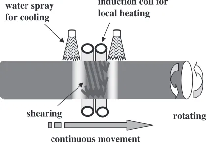
rest Al) was used as a specimen of Al–Mg alloy. Figure 1 illustrates the principle of the CREO technique. A portion of
a rod (30 mm2000 mm) was rotated at 25 rpm with
respect to the other portion around its longitudinal axis. Torsion strain was introduced in the zone, which separated the two portions rotating in opposite directions. The torsion straining zone was localized by softening the zone more than other portions by local heating (inner 588 K, outer 518 K) and cooling, as shown in Fig. 1. While producing the torsion straining zone, the rod was moved at 5 mm/s along the longitudinal axis, which produced continuous severe plastic strain throughout the rod. To create torsion strain efficiently, the torsion straining zone must be narrow, and the rotation of the rod should be fast relative to the speed of the rod. The initial grain sizes of the Al–Mg alloy prior to CREO were 30–
50mm. The average grain size of Al–Mg alloy after CREO
was confirmed by TEM observation to be 1.0–2.0mm.9)
water spray for cooling
induction coil for local heating
rotating
continuous movement shearing
Fig. 1 Schematic diagram of CREO.
*1This Paper was Originally Published in Japanese in J. Japan Inst. Metals 72(2008) 739–744.
*2Graduate Student, Kyushu University
[image:1.595.323.536.340.486.2]Prior to anodization, the Al–Mg alloy was carefully polished using No. 1500 emery paper and immersed in a 0.75 mol/L NaOH solution at 298 K for 30 s. Then, the alloy
was neutralized in a 0.48 mol/L HNO3 solution for 30 s and
electropolished at 293 K in a solution containing methanol
and perchloric acid (MeOH:HClO4¼4 : 1) at 10 V for
5 min. Anodization was performed in a solution containing
1.0 mol/L of H2SO4and 0.0185 mol/L of Al2(SO4)316H2O
at 293 K under a constant cell voltage of 15 V for 10 min; the solution was agitated at 100 rpm using a magnetic stirrer. The anodized Al–Mg alloy was colored by depositing Cu, Sn, Ni, or Co into micropores of Al oxide films by applying alternating current. Table 1 shows the conditions for the alternating current electrolysis.
The color of the anodized Al–Mg alloy was evaluated based on JIS-Z-8722-1982 using the colorimeter (CM-3610d; Konica Minolta Co.). A pulsed xenon lamp was used as a light source, and the color was measured in an area with a diameter of 25.5 mm. Both the specular component exclude (SCE) and specular component include (SCI) methods were utilized for color evaluation. In the SCE method, only diffuse reflectance light, with an exception of regular reflection, was measured to approach the visual estimation of a human; in the SCI method, the total reflectance light, including regular reflection, was measured to evaluate the inherent color of the material. The color was presented with reference to the
Lab system based on JIS-Z-8729:2004. The gloss was
measured at an angle of incidence of 45 using a digital
variable gloss meter (Suga Test Instrument Co.).
The surface roughness of electropolished Al–Mg alloy was measured using a SURFCOM1500DX-3DF (Tokyo Seimitsu Co.). The surface roughness was evaluated at a cutoff value of 0.8 mm and measurement length of 4 mm. The surface morphologies of electropolished Al–Mg alloy with and without anodization were observed by SEM. The Al–Mg alloy was immersed in a solution containing nitric and
phosphoric acid (HNO3:H3PO4¼94 : 6) at 358 K for 2 min
to observe the subgrain boundaries.
3. Results and Discussion
3.1 Coloring of anodized Al–Mg alloy by alternating current electrolysis
Anodized Al–Mg alloy was colored by alternating current
electrolysis. Visual observation confirmed that electrolysis of Cu, Sn, Ni, or Co turned the alloy red (Cu), yellow to gold (Sn), or reddish brown (Ni and Co). Table 2 shows the effect of CREO on the color of anodized Al–Mg alloys by alternating current electrolysis of Cu, Sn, Ni, or Co. The red coloration increases with the a-value, while green coloration increases when the value becomes more negative. On the other hand, yellow coloration increases with the b-value, and blue coloration increases as the b-value turns negative. In coloring by Cu electrolysis, the both the a- and b-values evaluated by the SCE method were higher for the alloys treated with CREO than those without CREO, while evaluation by SCI showed the a- and b-values to be hardly affected by CREO. In coloring by Sn, Ni or Co electrolysis, CREO had little effect on the a- and b-values, irrespective of the method for evaluation used.
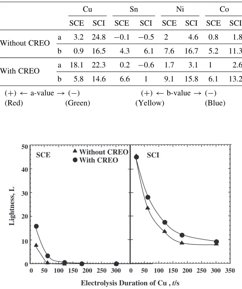
[image:2.595.47.291.84.239.2]Figure 2 shows the relationship between the lightness of anodized Al–Mg alloy colored by Cu electrolysis and the electrolysis duration. The SCE method showed decrease in the lightness with an increase in the duration of electrolysis, whether or not CREO was applied, reaching almost zero for durations longer than 100 s. For durations of 20 and 60 s, the lightness of anodized Al–Mg alloy was higher with CREO than without. On the other hand, in SCI method to evaluate the inherent color of materials, the lightness decreased with an increase in the duration of electrolysis. At the electrolysis durations longer than 60 s, the lightness of the anodized Al– Mg alloy was higher with CREO than without. At 20 s, the lightness evaluated by SCI was not affected by CREO; however, the lightness evaluated by SCE was higher with Table 1 Electrolysis conditions for coloring of anodized Al–Mg alloy.
Bath composition Operating conditions
CuSO45H2O 0.12 mol/L
Peak voltage of alternating current 10 V
H2SO4 0.10 mol/L
Frequency 50 Hz
Temperature 30C
SnSO4 0.047 mol/L
Electrolysis duration 20–300 s
H2SO4 1.0 mol/L
(Standard duration Cu: 60 s, Sn: 180 s) Counter electrode Pt NiSO46H2O 0.11 mol/L Peak voltage of alternating current 10 V
H3BO3 0.49 mol/L Frequency 50 Hz
CoSO47H2O 0.18 mol/L Temperature 30C
H3BO3 0.40 mol/L Electrolysis duration 150 s
[image:2.595.304.549.91.376.2]Glycerin 0.22 mol/L Counter electrode Pt
Table 2 Effect of CREO on color of anodized Al–Mg alloy with Cu, Sn, Ni or Co depsoition.
Cu Sn Ni Co
SCE SCI SCE SCI SCE SCI SCE SCI
Without CREO a 3.2 24.8 0:1 0:5 2 4.6 0.8 1.8 b 0.9 16.5 4.3 6.1 7.6 16.7 5.2 11.3
With CREO a 18.1 22.3 0.2 0:6 1.7 3.1 1 2.6 b 5.8 14.6 6.6 1 9.1 15.8 6.1 13.2 (+) a-value!() (+) b-value!() (Red) (Green) (Yellow) (Blue)
0 0
Electrolysis Duration of Cu , t/s 50
40
30
20
10
50 100 150 200 250 300 0 50 100 150 200 250 300 350
With CREO Without CREO
SCE SCI
Lightness, L
[image:2.595.306.547.93.380.2]CREO than without. This indicates that CREO decreases the intensity of regular reflection, and gloss.
Figure 3 shows the relationship between the lightness of the anodized Al–Mg alloy colored by Sn electrolysis and the electrolysis duration. The SCE method indicated lightness to be higher with CREO than without for all electrolysis durations, while the lightness evaluated by SCI showed little effect of CREO, except for 300 s of electrolysis. Although the inherent lightness of the anodized Al–Mg alloy colored by Sn electrolysis was hardly affected by CREO, the lightness, evaluated by SCE, increased with CREO.
Figure 4 shows the effect of CREO on the lightness of the anodized Al–Mg alloy colored by Ni or Co electrolysis. The evaluation by the SCE method showed that the lightness of the alloy colored by Ni or Co electrolysis was higher with CREO than without. On the other hand, the evaluation by the SCI method showed that the lightness of the alloy colored by Ni electrolysis was higher with CREO than without, but the alloy colored by Co electrolysis was hardly affected by CREO. As mentioned above, in all electrolytic colorings of Cu, Sn, Ni, and Co, the lightness of anodized Al–Mg alloys evaluated by SCE was higher with CREO than without.
Figure 5 shows the effect of CREO on the gloss of the anodized Al–Mg alloy colored by Cu, Sn, Ni, or Co electrolysis. In all electrolytic colorings of Cu, Sn, Ni, and Co, the gloss was lower with CREO than without, although there was a difference in the degree of the effect of the CREO treatment. In SCE method, the regular reflection is excluded to approach the visual evaluation of a human. The lightness of colored Al–Mg alloy evaluated by SCE increased with CREO, as shown in Figs. 2–4. This is attributed to the decrease in gloss caused by CREO.
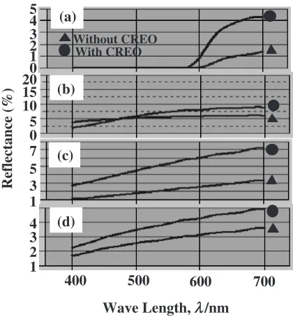
Figure 6 shows the reflectance of anodized Al–Mg alloy with electrolytic coloring, as evaluated by SCE. The reflectance was higher with CREO than without for almost all wavelengths, regardless of the metal deposited, corre-sponding to the increase in lightness evaluated by SCE with CREO.
Electrolysis Duration of Sn, t/s 50
80
70
60
40
30
20
0 50 100 150 200 250 300 0 50 100 150 200 250 300 350
With CREO Without CREO
SCE SCI
Lightness, L
Fig. 3 Relationship between lightness of anodized Al-Mg alloy colored by Sn deposition and duration of electrolysis.
Ni SCE
Ni SCI
Co SCE
Co SCI
without
CREO
without
CREO
without
CREO
without
CREO
with
CREO
with
CREO
with
CREO
with
CREO
60
50
40
30
20
10
0
Lightness, L
Fig. 4 Effect of CREO on lightness of anodized Al-Mg alloy colored by Ni or Co deposition.
Cu Sn Ni Co
Gloss, G
without
CREO
without
CREO
without
CREO
without
CREO with
CREO
with CREO with
CREO
with CREO
120
100 110
90
80
70
60
50
Fig. 5 Effect of CREO on gloss of anodized Al-Mg alloy colored by Cu, Sn, Ni or Co deposition.
(a)
Without CREO With CREO
(c) (b)
400 500 600 700 (d)
0 1 2 3 4 5
0 5 10 15 20
1 3 5 7
1 2 3 4
Wave Length, /nm
λ
Reflectance (%)
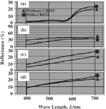
[image:3.595.56.284.74.213.2] [image:3.595.62.279.274.470.2] [image:3.595.322.532.315.542.2]Figure 7 shows the reflectance of anodized Al–Mg alloy with electrolytic coloring. The reflectance was evaluated by SCI. In Cu and Ni electrolysis, reflectance of the total reflection, including regular reflection, was higher with CREO than without, showing that CREO increases the inherent lightness of colored Al–Mg alloy.
3.2 Effect of CREO on the appearance of Al–Mg alloy without coloring
The effect of CREO on the lightness, gloss, and surface roughness of the Al–Mg alloy prior to coloring was investigated to clarify the reason why the lightness and gloss of anodized Al–Mg alloy with electrolytic coloring were affected by CREO. Figure 8 shows the effect of CREO on the lightness of electropolished Al–Mg alloys with and without anodization. Both Al–Mg alloys with and without anodiza-tion showed increase in lightness by CREO, regardless of the
[image:4.595.64.276.74.293.2]evaluation methods. The increase in lightness of anodized Al–Mg alloy with electrolytic coloring due to CREO is attributed to an increase in lightness of the Al–Mg alloy itself.
Table 3 shows the effect of CREO on the gloss of electropolished and anodized Al–Mg alloys. The gloss of Al–Mg alloys with and without anodization decreased by CREO. The increase in lightness (SCE) of Al–Mg alloy by CREO is attributed to this decrease in gloss. The surface roughness was measured to determine the reason for the decrease in gloss due to CREO. Table 4 shows the effect of CREO on the surface roughness, Ra, of electropolished Al– Mg alloys. CREO decreased the surface roughness of the alloys. The gloss generally increases with decreasing surface roughness; however, the gloss of Al–Mg alloys in this study decreased, despite the decrease in surface roughness by CREO. Therefore, the profile of surface roughness was then investigated.
Figure 9 shows the primary profiles of electropolished Al–Mg alloys with and without CREO. Although CREO decreased the surface roughness of the Al–Mg alloy, the surface waviness increased. Because the surface waviness of Al–Mg alloy increased by CREO, the gloss decreased despite a decrease in surface roughness.
3.3 Effect of CREO on the morphology of Al–Mg alloys
It seems that the enhancement of lightness of colored Al– Mg alloys with anodization from CREO is attributable to a decrease in gloss. However, the inherent lightness (SCI) of material colored with Cu and Ni electrolysis was also enhanced by CREO, as shown in Figs. 2 and 4. The morphology of electropolished Al–Mg alloys with and without anodization was observed by SEM to determine the reason for enhancement of the lightness of colored Al–Mg alloys due to CREO.
Figure 10 shows the SEM images of electropolished Al– Mg alloys with and without CREO. A number of subgrains
smaller than 1mm in size were observed, irrespective of
[image:4.595.304.549.95.152.2]whether CREO was applied or not. The size of subgrains was smaller with CREO than those without CREO.
Figure 11 shows SEM images of anodized Al–Mg alloys, in which the SEM images of (a), (b) and (c) is for the surface 0
10 20 30
0 30 60 90
0
0 10 10 20
20 30 30
Reflectance (%)
Wave Length, /nmλλ
400 500 600 700
Without CREO With CREO
(a)
(b)
(c)
(d)
Fig. 7 Effect of CREO on reflectance of anodized Al-Mg alloy colored by Cu (a), Sn (b), Ni (c) or Co (d) deposition (Reflectance evaluated by SCI).
without
CREO
without
CREO
without
CREO
without
CREO with
CREO
with CREO with
CREO
with CREO Al-Mg
SCE
Al-Mg SCI
Anodized Al-Mg
SCE
SCI
Lightness, L
70
60
50
40
30
20
10
0
[image:4.595.304.549.204.260.2]Fig. 8 Effect of CREO on lightness of electropolished Al-Mg alloy with anodization and without anodization.
Table 3 Effect of CREO on gloss of electropolished Al–Mg alloy with anodization and without anodization.
Gloss
Al–Mg Anodized Al–Mg
Without CREO 116.3 25
With CREO 113.8 20.6
Table 4 Effect of CREO on surface roughness Ra of electropolished Al– Mg alloy with anodization and without anodization.
Ra (mm)
Al–Mg Anodized Al–Mg Without CREO 0.075 0.19
[image:4.595.61.278.347.533.2]treated with CREO and of (d), (e), and (f) for that without CREO. The SEM magnification varies in (a) to (c) and (d) to (f). Anodic oxide films with pores about 10 nm in diameter were formed, irrespective of CREO. A number of white lines were observed over all anodic oxide films. TEM observation confirmed that the area of white line was salient, and the area surrounded by white line was reentrant. The area of the white line indicated by arrows in Figs. 11(c) and 11(f) has a lower density of micropores in anodic oxide films. The white line increased by CREO, and the total density of micropores in anodic oxide films consequently decreased. The enhance-ment of lightness (SCI) of the Al–Mg alloys colored with electrolysis of Cu and Ni due to CREO is ascribed to the decrease in density of the micropores in anodic oxide films. Since the shape of white line is similar to that of subgrain boundary of the Al–Mg alloy shown in Fig. 10, the white line seems to be formed on the subgrain boundary.
As mentioned above, the lightness of anodized Al–Mg alloy colored by alternating current electrolysis was en-hanced due to CREO, which is attributed to both the decrease in gloss of the Al–Mg alloy and the decrease in the micropore density in the anodic oxide films.
4. Conclusion
Continuous rotation evolutional control (CREO) affects the appearance of anodized Al–Mg alloy colored by alter-nating current electrolysis. Electrolysis colored the anodized Al–Mg alloys rufous (Cu), yellow to gold (Sn), or reddish brown (Ni and Co). The lightness of the colored Al–Mg alloys was significantly enhanced by CREO, regardless of the metal deposited. The gloss of the Al–Mg alloys decreased probably due to increase in the surface waviness resulting from CREO. The enhancement of the lightness of colored Al–Mg alloys treated by CREO is attributed to the decrease in the glossiness. SEM images showed that the density of the
(a)
(b)
[image:5.595.56.281.72.304.2](a)Without CREO (b)With CREO
Fig. 10 SEM images of electropolished Al-Mg alloy with CREO and without CREO.
(a)
(b)
(d)
(e)
(a),(b),(c):Without CREO
(d),(e),(f):With CREO
(c)
(f)
Fig. 11 SEM images of anodized Al-Mg alloy with CREO and without CREO.
-1.0 -0.5 0 0.5 1.0 1.5
0.5
1.0 1.5
3
3.5 4.0
-1.0 -0.5 0 0.5 1.0
0.5
1
2.0 2.5 3.0 4.0
1.5
-1.5 0
Without CREO
With CREO
Distance, d/mm
Height,
h
/
µ
m
[image:5.595.47.288.363.460.2] [image:5.595.82.516.531.746.2]micropores in anodic oxide films on Al–Mg alloys decreased as a result of CREO. This decrease in the density of the micropores may be assumed to enhance the lightness of the colored Al–Mg alloys treated by CREO.
Acknowledgments
This work was supported by a Research Promotion Grant from User Science Institute of Kyushu University.
REFERENCES
1) T. Asada: Kinzoku Hyomen Gijutsu21(1970) 490–497.
2) M. Nagayama, H. Takahashi and M. Koda: Kinzoku Hyomen Gijutsu
30(1979) 438–456.
3) N. Baba:Anodic Oxide Films Produced by Electrolysis, (in Japanese, Maki Syoten, Tokyo, 1996) pp. 14–47.
4) K. Wada, Y. Matsui, M. Tsutsumi and R. Uchida: Kinzoku Hyomen Gijutsu31(1980) 140–145.
5) K. Wada, Y. Matsui, M. Tsutsumi and R. Uchida: Kinzoku Hyomen Gijutsu31(1980) 307–312.
6) K. Nakamura, K. Neishi, K. Kaneko, M. Nakagaki and Z. Horita: Mater. Trans.45(2004) 3338–3342.
7) K. Nakamura, K. Neishi, K. Kaneko, M. Nakagaki and Z. Horita: Mater. Sci. Forum503–504(2006) 385–390.
8) Y. Kawasaki, K. Neishi, Y. Miyahara, K. Nakamura, K. Kaneko, M. Nakagaki and Z. Horita: Mater. Sci. Forum503–504(2006) 943–948. 9) Y. Miyahara, N. Emi, K. Neishi, K. Nakamura, K. Kaneko, M. Nakagaki and Z. Horita: Mater. Sci. Forum503–504(2006) 949–954. 10) K. Neishi, A. Higashino, Y. Miyahara, K. Nakamura, K. Kaneko, M. Nakagaki and Z. Horita: Mater. Sci. Forum503–504(2006) 955–960. 11) H. J. Gohausen and G. C. Schoener: Surf. Finish. (1984) 56–63. 12) T. Kawaguchi, S. Ono, T. Satoh and N. Masuko: Kinzoku Hyomen
Gijutsu41(1990) 690–694.
13) S. Ishida and S. Itoh: Kinzoku Hyomen Gijutsu41(1990) 1054–1058. 14) K. Kawai, M. Yamamuro and K. Wada: Hyomen Gijutsu49(1998)
1016–1020.
15) M. Yamamuro and S. Morisaki: J. Jpn. Inst. Light Met.51(2001) 234– 237.
16) Y. Tsukamoto and K. Ebihara: Kinzoku Hyomen Gijutsu50(1999) 565–567.
17) S. Van Gils, P. Mast, E. Stijns and H. Terry: Surf. Coat. Technol.185
(2004) 303–310.