Formation of Fe-Based Amorphous Coating Films
by Thermal Spraying Technique
Masahiro Komaki
1, Tsunehiro Mimura
1, Yuji Kusumoto
1,
Ryurou Kurahasi
1, Masahisa Kouzaki
2and Tohru Yamasaki
3 1Nakayama Steel Works, Ltd., R&D Division, Osaka 551-8551, Japan2Nakayama Steel Works, Ltd., Osaka 551-8551, Japan 3University of Hyogo, Himeji 671-2280, Japan
Some amorphous Fe-Cr-P-C coating films having high hardness and high corrosion resistance have been produced by a newly developed thermal spraying technique. In order to control the temperatures of the powder particles in the flame spray and the substrate, a newly developed cylindrical nozzle, with external cooling nitrogen gas, was mounted to the front end of the thermal spraying gun. Fe70Cr10P13C7films with
various external cooling gas velocities between 20 m/s and 40 m/s exhibited entire amorphous structure without oxides and/or unmelted particles. Corrosion-resistance of the films was observed in immersion tests using various corrosive liquids. An amorphous film was formed on the surface of the shaft sleeve of the slurry pump by using the cylindrical nozzle. This shaft sleeve was installed in the slurry pump of chemical fertilizer maker’s production line and the life test was done under the real operation condition for two months.
[doi:10.2320/matertrans.MAW201022]
(Received April 27, 2010; Accepted June 1, 2010; Published August 25, 2010)
Keywords: iron-chromium-phosphorus-carbon, amorphous coating film, thermal spraying method, rapid cooling, hardness, corrosion resistance
1. Introduction
Thermal spraying is a superior technique for producing amorphous alloy coating films with large area on various industrial materials.1–4) Especially, Fe-Cr based amorphous alloys have high hardness and high corrosion resistance.5–8) However, the Fe-Cr based amorphous alloys having high melting temperatures of about 1000C have not yet been
well produced by previous thermal spraying methods. The important problems in these methods may be due to the contamination of oxide and the density of pores in the thermal sprayed films.1,2,9–13) Recently, there are some
research papers that were able to inhibit the oxide formation by the shield nozzle installed at the front end of the atmospheric plasma spray gun or the high velocity oxygen fuel gun.14,15)
In the present study, formation of some amorphous Fe-Cr-P-C coating films having high hardness and high corrosion resistance have been demonstrated by a newly developed thermal spraying technique. In order to control the temper-atures of the powder particles in the flame spray and the substrate, a newly developed cylindrical nozzle with external cooling nitrogen gas was mounted at the front end of the thermal spraying gun. Cooling rates of the sprayed samples on SUS316L substrates were estimated to attain about
106C/s by measuring the temperature gradient of the
spraying flame.
2. Experimental Procedures
The thermal spraying equipment used in this study was composed of a gas flame spraying gun and a newly developed cylindrical nozzle. The thermal spraying material was gas-atomized powder (grain size: 38–63mm) of Fe70Cr10P13C7
(at%) with a melting temperature of 997C. A SUS316L (100mm50mm3:2mm) substrate, shot blasted by
alumina powder, was used. In order to keep a reduction atmosphere in the flame, an acetylene-rich gas fuel mixture was used. Nitrogen gas was introduced into the cylindrical nozzle to prevent the formation of oxides in the coating film. The thermal spray gun was mounted on a robot arm, scanned at the rate of 300 mm/s in feed rate and 10 mm in spraying pitch, and an alloy layer of up to 500mmin film thickness was produced. Structural analysis of the coating films was done by X-ray diffraction (Cu K radiation with a graphite monochromator, 40 kV-200 mA) and transmission electron microscope (TEM:HF2000-200 kV). The amorphous alloy coating films, separated from the substrate, were immersed in various kinds of corrosive liquid for the maximum period of 4-weeks. For comparison, standard specimens of Hastelloy C and commercially produced pure titanium were used. An amorphous film was formed on the surface of the shaft sleeve of the slurry pump by using the cylindrical nozzle. This shaft sleeve was installed in the slurry pump of chemical fertilizer maker’s production line and the life test was done under the real operation condition for two months.
Figure 1 shows a schematic illustration of cylindrical-nozzle type thermal spray gun. In order to control the temperatures of the powder particles in the sprayed flame and the substrate, and to prevent the formation of oxides in the coating film, a newly developed cylindrical nozzle with external cooling nitrogen gas was mounted at the front end of the thermal spraying gun.
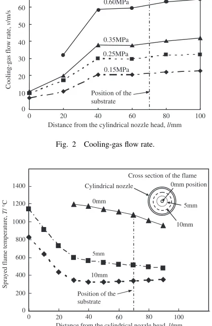
Figure 2 shows the cooling-gas flow rate, over the distance from the cylindrical nozzle head to the substrate, measured by a pitot tube. The cooling-gas flow rate can be controlled up to 60 m/s by adjusting the gas pressure in the cylindrical nozzle. To keep the optimal temperature and flow states of the spraying flame, the flow rate of the cooling gas was set to the nearly equal to that of the spraying flame. In this study, optimal flow rate of the sprayed flame was
3040m/s.16)
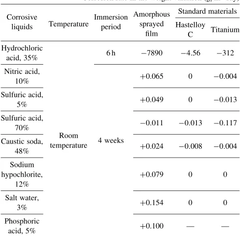
Figure 3 shows the thermal gradients of the spraying flame, over the distance from the cylindrical nozzle head to the substrate, measured by a thermocouple. In this diagram, the 0 mm gradient curve indicates the thermal gradient at the flame center, while the 5 mm and 10 mm gradient curves indicate the thermal gradient at the positions outlying from the center of flame. Although the center of flame hits the substrate at a temperature of approximately 1000C, the flame temperature decreased sharply to about 300 to 500C for the 10 mm and the 5 mm respectively positions.
Figure 4 shows the compositions of the thermal spraying flame, over the distance from the cylindrical nozzle head to 20 mm and 70 mm, measured by the orsat apparatus. In this experiment, nitrogen gas or compression air were used as a cooling gas. In order to keep a reduction atmosphere in the spraying flame, an acetylene-rich gas fuel mixture was used. When nitrogen gas was used, oxygen was contained in the spraying frame, 0.2% and 0.8% at positions of 20 mm and 70 mm away from the cylindrical nozzle head, respectively. On the other hand, when compression air was used, oxygen was contained 8% and 14% in the spraying frame at same positions.
3. Results
3.1 Structure of the coating films
Figure 5 shows the optical micrographs in cross-section of the thermal spray coating films with and without the newly developed cylindrical nozzle. When the thermal spray gun without the cylindrical nozzle was used, many inclusions of oxides have been observed in the coating film as shown in
C2H2
O2
Flame
Molten range Quenching range
Spraying film Cooling gas N2 Cooling gas N2
Spray powder material (Carrier gas: N2)
Cylindrical nozzle head Internal
cooling gas
Cylindrical nozzle (twofold cylinder)
Front end of thermal spray-gun nozzle
Substrate
Fig. 1 Schematic illustration of cylindrical-nozzle type thermal spraying gun.
Cooling-gas flow rate,
v
/m/s
Distance from the cylindrical nozzle head, l/mm 0.60MPa
0.35MPa
0.25MPa
0.15MPa
0 20 40 60 80 100
70
60
50
40
30
20
10
0
Position of the substrate
Fig. 2 Cooling-gas flow rate.
Sprayed flame temperature,
T
/
°
C
Distance from the cylindrical nozzle head, l/mm 0mm
5mm
10mm
0 200 400 600 800 1000 1200
0 20 40 60 80 100
1400
5mm
10mm Cylindrical nozzle
Cross section of the flame 0mm position
Position of the substrate
Fig. 3 Flame temperature gradient.
Composition of the spraying flame (vol.%)
Distance from the cylindrical nozzle head, l/mm 0
5 10 15 20
0 5 10 15 20
0 5 10 15 20
CO
20mm 70mm 20mm 70mm
O2
CO2
Cooling Gas:N2 Cooling Gas:Air
CO
O2
CO2
[image:2.595.113.490.74.246.2] [image:2.595.325.533.285.481.2] [image:2.595.62.277.298.629.2]Fig. 5(a). On the other hand, shown in Fig. 5(b), when the thermal spray gun with the cylindrical nozzle was used, high-quality amorphous sprayed film without the inclusion of oxides can be produced.
Figure 6 shows the X-ray diffraction patterns of the thermal spray coating films with and without the cylindrical nozzle. When the thermal spray gun without the cylindrical nozzle was used, crystalline peaks from many kinds of oxides were observed. On the other hand, when the thermal spray gun with the cylindrical nozzle was used, X-ray diffraction peaks are well-broadened, indicating structure of the film is the amorphous.
Figure 7 shows a TEM image and a selected area diffraction pattern (SADP) of the sprayed coating film fabricated by using the cylindrical nozzle. It consists of amorphous phase in general. The SADP with halo rings also supports that the coating film has an amorphous structure. Compositions of the coating film obtained by EDX analysis are as follows; Fe: bal, Cr: 11.6 at%, P: 13.7 at%, indicating a similar composition to that of the gas-atomized powder.
3.2 Corrosion tests
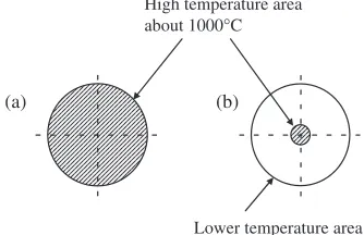
The amorphous alloy coating films separated from the substrates were immersed in various kinds of corrosive liquid. For comparison, standard specimens of Hastelloy C and commercially produced pure titanium were used. Table 1 shows the results of the corrosion tests. In the corrosion standard for chemical plant materials, a corrosion rate in the weight variation of between00:5g/m2 day is considered
good.17)Corrosion of the amorphous sprayed film scarcely
progressed after an initial increase arising from the gener-ation of an oxide layer. On the other hand, both Hastelloy C and titanium slightly corroded. Accordingly, the corrosion tests have clarified that the sprayed amorphous film exhibited a high corrosion resistance, equal to that of Hastelloy C and commercially produced pure titanium, under most condi-tions. However, the corrosion resistance test in hydrochloric acid did not show a favorable result for the Fe70Cr10P13C7
film. The corrosion liquids containing strong oxidizers such as nitric acid and sulfuric acid etc. usually exhibit the high formability of the passive films on the sample surface. On the contrast, the hydrochloric acid is the nonoxidizing acid,
(a) (b)
Substrate (SUS316L)
Amorphous
Substrate (SUS316L)
Amorphous
Oxide
Fig. 5 Optical micrographs in the cross section of the coating films: (a) Without the cylindrical nozzle; (b) With the cylindrical nozzle.
20° 40° 60° 80° 100°
2θ
With the cylindrical nozzle Without the cylindrical nozzle
Intensity
Fig. 6 X-ray diffraction patterns of the spray coating films.
Diffracted pattern Site being diffracted and EDX analyzed
[image:3.595.104.496.75.208.2]Fig. 7 TEM image of the spray coating film with the cylindrical nozzle.
Table 1 Results of the corrosion tests.
Corrosion rate in the weight variation (g/m2day)
Corrosive
Temperature Immersion Amorphous
Standard materials
liquids period sprayed
film
Hastelloy
C Titanium
Hydrochloric
acid, 35% 6 h 7890 4:56 312
Nitric acid,
10% +0.065 0 0:004
Sulfuric acid,
5% +0.049 0 0:013
Sulfuric acid,
70% 0:011 0:013 0:117
Caustic soda, 48%
Room
temperature 4 weeks +0.024 0:008 0:004
Sodium hypochlorite,
12%
+0.079 0 0
Salt water,
3% +0.154 0 0
Phosphoric
[image:3.595.57.283.252.340.2] [image:3.595.304.549.271.513.2] [image:3.595.58.278.391.494.2]indicating the formation speed of the passive film may be slower than that of the other liquids.
3.3 Life test of the sprayed coated slurry pump shaft sleeve
[image:4.595.62.275.74.226.2]An amorphous film was formed on the surface of the shaft sleeve of the slurry pump by using the cylindrical nozzle. This shaft sleeve was installed in the slurry pump of chemical fertilizer maker’s production line and the life test was done under the real operation condition for two months.
Figure 8 shows the diagrammatic illustration of the slurry pump. The shaft sleeve of the slurry pump was worn easily because of the griding effects of slurry that sandwiched between the driving shaft and the seal. Therefore, the development of the material of high hardness and high corrosion resistance has been demanded.
Table 2 shows the life test conditions for the shaft sleeve of the slurry pump. Surface of the SUS304 shaft sleeve was shot blasted by alumina powder, and then NiCr undercoat layer with about 50mmthickness was formed. The Fe-Cr-P-C amorphous film of 300mmthickness was coated on the NiCr layer. Finally the surface of the coated shaft sleeve was ground with a diamond grindstone and finished up. As a result, the thickness of the remained Fe-Cr-P-C coating film was about 150mm.
Figure 9 shows the wear track of the shaft sleeve after life test for two months. There is no wear track in the amorphous thermal spraying shaft sleeve though wear track of 4mmis admitted in conventional SCS23 product (Fe: bal,
Cr: 20 mass%, Ni: 30 mass%, Mo: 3 mass%, Cu: 3 mass%). The amorphous thermal spraying shaft sleeve indicated high corrosion resistance and high abrasion resistance (HV700900).
4. Discussion
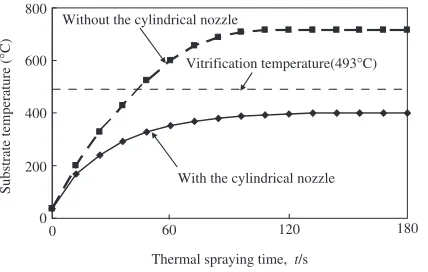
Figure 10 shows a schematic diagram explaining the temperature distribution of the flame just prior to the inpact on the substrate. When the cylindrical nozzle is not used, the high temperature area at about 1000C is spread over the
entire flame. In contrast, when the cylindrical nozzle is used, the high temperature area is well converged to the center of the flame as expected from the results of Fig. 3.
Slurry inhalation Slurry exhalation
Seal
Pump drive shaft
Impeller
Liner Cover plate Fe-Cr-P-C amorphous
coated shaft sleeve
Fig. 8 Diagrammatic illustration of the slurry pump.
Table 2 Test conditions and results of the varification test by using the amorphous coated and uncoated shaft sleeve of the slurry pump.
Item Conventional product Material under test
Substrate: SUS304
Material SCS23 Under coat: NiCr 50mm
Top coat: Fe70Cr10P13C7
150mm
Test circumstance Slurry pump of chemical fertilizer maker’s production line
Required performance
High hardness and high corrosion resistanc in slurry of pH2
Depth of wear track
after two months 4mm 0mm
Wear track with slurry and seal
SCS23 material Depth of wear track : 1.5µm
0 0
4
Fe70Cr10P13C7 coated material
µm
µm
µm
Fig. 9 Wear track of the shaft sleeve after two months.
Lower temperature area
(a) (b)
High temperature area about 1000°C
[image:4.595.306.549.93.228.2] [image:4.595.83.515.272.400.2] [image:4.595.342.509.447.555.2]Figure 11 shows the changes of the substrate temperature as a function of the thermal spraying time with and without the cylindrical nozzle. The thermal spray gun was mounted on a robot arm, scanned at the rate of 300 mm/s in feed rate and 10 mm in spraying pitch. Temperature of the substrate at the surface center point was measured by radiation ther-mometer. When the thermal spray gun without the cylindrical nozzle was used, a hot area expands over all the flame, thus causing a rapid increase of substrate temperature beyond the vitrification point (493C) and, accordingly, crystallization of
the coating occured easily. In contrast, when the thermal spray gun with the cylindrical nozzle was used, the substrate temperature saturated gradually under the vitrification tem-perature (400C), indicating the high formability of the
amorphous film. Therefore, the high scanning speed of 300 mm/s is very effective for rapid cooling of the coating films, preventing the crystallization of the former coated amorphous layer.
5. Summary
Some amorphous Fe-Cr-P-C coating films having high hardness and high corrosion resistance have been produced by a newly developed thermal spraying technique. In order to control the temperatures of the powder particles in the flame spray and the substrate, a newly developed cylindrical nozzle with external cooling nitrogen gas was mounted to the front end of the thermal spray gun. When the thermal spray gun with the cylindrical nozzle was used, the substrate
temper-ature increased gradually because of the lower tempertemper-ature area surrounding the high temperature area of about 1000C.
Cooling rates of the sprayed samples on SUS316L substrates were estimated to attain about 106C/s by measuring the
temperature gradient of the spraying flame. Fe70Cr10P13C7
films with various external cooling gas velocities between 20 m/s and 40 m/s exhibited an entirely amorphous structure without oxides and/or unmelted particles. Corrosion testing has clarified that the sprayed amorphous films exhibited a high corrosion resistance equal to that of Hastelloy C and commercially produced pure titanium. An amorphous film was formed on the surface of the shaft sleeve of the slurry pump by using the cylindrical nozzle. This shaft sleeve was installed in the slurry pump of chemical fertilizer maker’s production line and the life test was done under the real operation condition for two months. The amorphous thermal spraying shaft sleeve indicated high corrosion resistance and high abrasion resistance.
REFERENCES
1) A. Kobayashi, S. Yano, H. Kimura and A. Inoue: Surf. Coat. Technol.
202(2008) 2513.
2) Z. Zhou, L. Wang, F. C. Wang, H. F. Zhang, Y. B. Liu and S. H. Xu: Surf. Coat. Technol.204(2009) 563.
3) A. H. Dent, A. J. Horlock, D. G. McCartney and S. J. Harris: Surf. Coat. Technol.139(2001) 244.
4) S. Yoon, H. J. Kim and C. Lee: Surf. Coat. Technol.200(2006) 6022. 5) M. Naka, K. Hashimoto and T. Masumoto: J. Japan Inst. Metals38
(1974) 835.
6) K. Hashimoto: J. Japan Inst. Metals15(1976) 203. 7) K. Hashimoto: J. Japan Inst. Metals18(1979) 362.
8) K. Asami, H. Kimura and A. Inoue: J. Jpn. Soc. Powder Powder Metall.
54(2007) 795.
9) K. Kishitake, H. Era and F. Otsubo: J. JTSS5(1996) 476.
10) F. Otsubo, H. Era and K. Kishitake: Quarterly J. Japan Weld. Soc.19
(2001) 54.
11) M. Fukumoto, C. Yokoi, M. Yamada, T. Yasui, M. Sugiyama, M. Ohara and T. Igarashi: Quarterly J. Japan Weld. Soc.25(2007) 323. 12) M. Fukumoto, Y. Okuwa, M. Yamada, T. Yasui, Y. Motoe, K.
Nakashima and T. Igarashi: Quarterly J. Japan Weld. Soc.26(2008) 74. 13) N. Nagao, M. Komaki, R. Kurahashi and Y. Hrihara: J. Japan Inst.
Metals71(2007) 742.
14) T. Fukushima and S. Kuroda: Quarterly J. Japan Weld. Soc.20(2002) 439.
15) N. Sakakibara, Y. Manabe, Y. Hiromoto and Y. Kobayashi: Quarterly J. Japan Weld. Soc.24(2006) 181.
16) A. Hasui: Shinpan-youshakougaku, (Sanpoushuppan, Tokyo, 1996) p. 28.
17) S. Hatano: Kagakusouti-zairyoutaisyokuhyou, (Kagakukougyosya, Tokyo, 1984) p. 194.
0 200 400 600 800
0 60 120 180
Thermal spraying time, t/s With the cylindrical nozzle Without the cylindrical nozzle
Vitrification temperature(493°C)
Substrate temperature (
°
[image:5.595.65.279.73.209.2]C)