High energy supercapattery with an ionic liquid solution of LiClO4 1
Linpo Yu,a,b and George Z. Chena,b* 2
a
Department of Chemical and Environmental Engineering, and Energy and Sustainability 3
Research Division, the University of Nottingham, Nottingham, NG7 2RD UK 4
Email: [email protected] 5
b
Department of Chemical and Environmental Engineering, and Centre for Sustainable Energy 6
Technologies, Faculty of Science and Engineering, the University of Nottingham Ningbo China, 7
Ningbo, 315100 China 8
9
Abstract: 10
Supercapattery combining an ideally polarized capacitor-like electrode and a battery-like 11
electrode is demonstrated theoretically and practically using an ionic liquid electrolyte 12
containing 1-butyl-1-methylpyrrolidinium tri(pentafluoroethyl)trifluorophosphate (BMPyrrFAP), 13
gamma-butyrolactone (γ-GBL) and LiClO4. The electrochemical deposition and dissolution of
14
lithium metal on a platinum and glass carbon electrode were investigated in this ionic liquid 15
solution. The CV data shows the fresh electrochemical deposited lithium metal is stable in the 16
electrolyte, which encourages the investigation of this ionic liquid solution in supercapattery 17
with a lithium battery negative electrode. The active material counted specific energy of the 18
supercapattery based on a lithium negative electrode and an activated carbon (Act-C) positive 19
electrode can reach 230 Wh kg-1 under the Galvanostatic charge-discharge current density of 1 20
mA cm-2. The positive electrode material, Act-C was also investigated by CV, AC impedance, 21
SEM and BET. The non-uniform particle size and micropore porous structure of the Act-C 22
enable its electric double layer capacitor (EDLC) behavior in the ionic liquid solution. The 23
This is the accepted manuscript which differs slightly from the finally published version. http://dx.doi.org/10.1039/C5FD00232J
calculated specific capacitance of the C in this ionic liquid solution is higher than same Act-1
C in aqueous solution, which indicates the pseudocapacitance behaviour of Act-C with the 2
species in the ionic liquid electrolyte. 3
4
Introduction 5
Supercapattery (=supercapacitor + battery) takes the advantages of both supercapacitor 6
(also known as electric double layer capacitor, or EDLC) and battery by combining an ideally 7
polarized capacitor-like electrode and a battery-like electrode.1 Although lithium ion capacitor2,3 8
is also comprised of this hybrid configuration, supercapattery is the more general term of the 9
particular design. 10
In theory, supercapattery can possess higher energy density than both battery and 11
supercapacitor and can supply this energy at a power output almost as high as supercapacitor. 12
The high power output of supercapattery is mainly a result of sharing the same electrochemical 13
active materials with supercapacitor, where the nanostructured carbons, like activated carbon 14
(Act-C), carbon nanotubes (CNTs) and graphene are the best choice for the ideally polarized 15
electrode because of their large surface area, porosity, stability over a wide potential window, 16
and intrinsically low electrical resistance. In addition, pseudo-capacitive materials including 17
MnO2, RuO2 and conducting polymers can also be used as the capacitor-like electrode materials
18
providing the high electrode capacitance, but limiting the potential windows. 19
As to the battery-like electrode, various electrode materials from commercial battery 20
systems can be the candidate, from lead acid batteries to metal/air systems, but in practice, metal 21
compounds3-5 like SnO2, MnO2 and LiFePO4 are more common and commercially available.
22
would output a cell voltage about 6.1 V and offer a specific energy content of 6304 Wh kg-1. Any 1
battery cannot go beyond the specific energy content of the hypothetical F battery. As to Li-2
ion battery (LixC6 | Li1-xCoO2), the theoretical specific energy is 552 Wh kg-1 at 3.5 V. A
3
hypothetical supercapattery comprising a lithium metal negative electrode and a supercapacitor 4
positive electrode (assumed 400 F g-1) is evaluated and analyzed here. Considering the specific 5
charge capacity of lithium is much larger than that of the supercapacitor electrode, the mass of 6
the lithium metal is negligible. The theoretical specific energy value would be 625 Wh kg-1 for 7
the cell voltage vary from 3.5 V to 1.0 V. This theoretical value is even higher than the one of 8
the Li-ion battery. 9
The above calculation is based on the equation of the capacitor energy, Eq. 1, 10
2 max max
2 1
CU
E (1) 11
where C is the specific capacitance of a capacitor, and Emax is the maximum energy capacity of a
12
capacitor correlated to its maximum tolerable voltage, Umax. It should be mentioned that a hybrid
13
cell of a battery electrode and a supercapacitor electrode does not always show typical 14
supercapacitor behaviour, where the cell voltage (U) is always proportional to the time (t) during 15
a constant current charging or discharging test. If the cell presents battery like features, the term 16
supercabattery is recommended,6 but not discussed in this paper. In the case of supercapattery, 17
the Umax is a key factor for the energy capacity of the devices. Because the behaviour of
18
supercapattery is close to that of supercapacitor,1 several strategies that have been applied in 19
supercapacitor can be utilized in supercapattery to improve the practical energy capacity, such as 20
using the design of asymmetric supercapacitor cell,7 controlling the capacitance ratio of the 21
positive and negative electrode made from the same material,8 and serially stacking the cells 22
is a strong desire for changing the aqueous to organic electrolytes to achieve a high working 1
voltage. 2
Recent studies have revealed both aqueous and non-aqueous supercapatteries using lithium 3
metal10 and Li-ion battery material3 as the electrode. An aqueous supercapattery consisting of a 4
MnO2 positive electrode and a Li/LISICON/PEO-LiTFSI/Li+ negative electrode had achieved a
5
specific energy capacity of 114 Wh kg-1 with a 4.3 V cell voltage.10 The Li/LISICON/PEO-6
LiTFSI/Li+ electrode is a multi-layered Li electrode, which consists of lithium metal, a 7
LISICON-type solid glass ceramic as the water-stable solid electrolyte, and a buffer layer 8
consisting of polyethylene oxide with Li(CF3SO2)2N polymer electrolyte (PEO-LiTFSI) between
9
the lithium metal and the solid electrolyte. If MnO2 is replaced by RuO2 as the positive electrode,
10
the specific energy capacity of the device comes to 520 Wh kg-1 with a 3.8 V cell voltage.10 11
However, the current density of the aforementioned devices is only 0.255 mA cm-2, which is 12
limited by the solid/liquid interphase. This disadvantage prevents these high energy capacity 13
devices in any high power application. Another non-aqueous supercapattery using LiFePO4 as
14
the positive electrode and Cabot carbon black as the negative electrode possesses good cycling 15
stability at high current density in a Li-ion contained propylene carbonate (PC) electrolyte.3 16
However, the potential range of the Cabot carbon black can only keep its capacitor-like 17
behaviour from 2.80 to 1.25 V vs. Li/Li+ in the electrolyte, which has limited the cell voltage. 18
Ionic liquids are specially featured by their zero or negligible volatility, but still able to offer 19
the highly ionic environment, and wide temperature and potential windows.11 They have brought 20
about unique opportunities, including synthesis,12 trace analysis,13,14 thermochromic/cryochromic 21
be chosen as competitive candidates for the electrolytes of supercapattery when the battery-1
behaviour electrode is a lithium-ion or lithium battery negative electrode. 2
Here, we report the recent supercapattery work based on an activated carbon positive 3
electrode and a Li/Li+ negative electrode using an ionic liquid electrolyte, 1-butyl-1-4
methylpyrrolidinium tri(pentafluoroethyl)trifluorophosphate (BMPyrrFAP) containing gamma-5
butyrolactone (γ-GBL) and LiClO4. The characterization of the activated carbon has been done
6
and presented here, including the data of cyclic voltammogram (CV), AC impedance, SEM and 7
BET. The demonstrated supercapattery cell shows a clear capacitor-like behaviour in the CV and 8
Galvanostatic charge and discharge (GCD) tests. This particular hybrid design ensures the full 9
usage of the electrochemical window of the ionic liquid solution and the capacitance of the 10
activated carbon, and basically maintains the high power of the supercapacitor. 11
12
Experimental 13
In this work, a supercapacitor grade commercial product of activated carbon (Act-C, YP50F, 14
Kuraray Chemical Co.) was used. The other chemicals, 1-butyl-1-methylpyrrolidinium 15
tri(pentafluoroethyl)trifluorophosphate (BMPyrrFAP, Merck), 1-ethyl-3-methylimidazolium 16
tetracyanoborate (EMIM[B(CN)4], Merck), gamma-butyrolactone (γ-GBL, Sigma Aldrich) and
17
LiClO4 (Sigma Aldrich), were commercially available and used without further purification.
18
Lithium metal (foil, Sigma Aldrich) was kept and handled in an argon filled glove box. The 19
homemade electrochemical cells (2-electrode/3-electrode cells and sandwich type cell) were 20
fabricated in an argon-filled glove box (O2 < 10 ppm, H2O < 10 ppm) and transferred outside the
21
glove box for the electrochemical experiments by an AUTOLAB 302N potentiostat. Membrane 22
For the electrochemical tests, the Act-C powder was made into pellet type and casted 1
electrodes with PTFE and PVDF, respectively. The details of fabricating the Act-C/PTFE pellet 2
electrode can be found in previous publication from this laboratory.21 The Act-C/PVDF electrode 3
was fabricated by the following process. 10 µL of an Act-C suspension (0.950 g Kuraray Act-C 4
and 0.050 g PVDF powder in 20 mL DMSO suspension) was dropped on a 5 mm diameter 5
graphite disc electrode. The electrode loaded with 0.5 mg of Act-C composite (95 % w. Act-C 6
and 5 % w. PVDF) was dried in a vacuum oven at 75 ○C overnight, and then was ready for the 7
electrochemical tests. 8
All the experiment is operated at room temperature. More experimental details are specified 9
in the following sections. 10
11
Results and discussion 12
The pore size and volume distribution of an Act-C are the most important physical 13
characteristics. Fig. 1 presents the SEM images of an Act-C pellet containing 5 % w. PTFE. The 14
Act-C powder is non-uniform in particle size, and the PTFE is binding the Act-C particles like a 15
spider web to maintain the mechanical strength of the Act-C pellet. The surface area of the 16
Kuraray Act-C sample is 1724 m2 g-1 determined from the nitrogen absorption/desorption 17
isotherms at 77 K (ASAP 2420) by applying the density function theory (DFT). In previous 18
work,21 the dominant range of pore widths of the same Kuraray Act-C sample is between 1.5 and 19
2.5 nm. For an aqueous electrolyte, its wetting ability with the Act-C pellet will affect the contact 20
between the electrolyte and C particles, and vary the charge storage performance of the Act-21
C sample. As to the organic electrolyte, the wetting is not a problem anymore, while the 22
A theory was proposed for the traditional organic electrolyte, that the longer the pore inside the 1
particle is, the poorer performance of the capacitance of the porous carbon materials is. 3 This is 2
mainly due to the ion block of the pores by the non-ionic solvent molecular. Similar phenomenon 3
was also observed in the case of aqueous electrolyte with organic additive.21 4
5
Fig. 1 SEM images of the activated carbon pellet (including 5 % w. PTFE). The insert is the 6
enlarge view of the back image. 7
8
Before the work on the supercapattery, we have investigated the Kuraray Act-C in a 9
commercial ionic liquid, 1-ethyl-3-methylimidazolium tetracyanoborate (EMIM[B(CN)4]). Fig. 2
10
shows the photo of electrochemical tube cell and test results on CV, GCD and AC impedance. A 11
small piece of Act-C pellet (about 1 mg, containing 5 % w. PTFE) was loaded on a 6 mm 12
diameter graphite disc electrode. Another graphite disc attaching 30 mg Act-C was used as the 13
counter electrode. Reference electrode is a Ag/Ag+ electrode filled with 0.01 mol L-1 AgNO3
14
acetonitrile solution, which is connected to the electrolyte via a salt bridge filled with 15
EMIM[B(CN)4]. This reference can be prepared following the method described in reference.22 It
[image:7.612.46.509.52.717.2]should be mentioned that the reference electrode is changed to Li/Li+ electrode in the latter 1
discussion except in Fig. 2. Any potential in this paper will be suffixed with the reference 2
electrode used in the experiment. 3
4
Fig. 2 (A): Photograph of the tube cell. 1.064 mg Act-C (including 5% w. PTFE) was loaded on 5
the graphite disc as working electrode. EMIM[B(CN)4] was filled in the tube as electrolyte.
6
Reference electrode is Ag/Ag+ electrode in 0.01 mol L-1 AgNO3 acetonitrile solution connected
7
to the electrolyte via a salt bridge filled only with EMIM[B(CN)4]. The results in (B), (C) and
8
(D) were collected from this tube cell. 9
(B): CVs of the tube cell. Scan rate: 20 mV s-1. 10
(C): Galvanostatic Charge-Discharge plots of the tube cell. Current: 1 mA. 11
(D): Nyquist plots of the tube cell at potentials indicated in the figure. 12
[image:8.612.88.478.158.454.2]Both CVs and AC impedance results in Fig. 2 indicate that the Kuraray Act-C doesn’t show 1
a pure EDLC performance in EMIM[B(CN)4]. The Act-C can store more charge in a potential
2
range from -1.7 to 0 V vs. Ag/Ag+ than the range of 0 to 1.0 V vs. Ag/Ag+. If a symmetrical 3
supercapacitor was fabricated using this Act-C and ionic liquid, the maximum voltage could not 4
go beyond 2.7 V. The calculated specific capacitance value of Kuraray Act-C in EMIM[B(CN)4]
5
is about 100 F g-1, which is comparable to the value of the same sample got in aqueous 6
solution.21 The voltage of this ionic liquid based symmetrical cell is not increased dramatically, 7
while the resistance of the cell will increased compared to the cell using an aqueous electrolyte. 8
In this case, changing electrolyte from an aqueous to a non-aqueous electrolyte is not economic. 9
A new strategy should be made to improve the energy capacity of the cell. 10
As aforementioned, the lithium battery or Li-ion battery processes very high energy capacity 11
mainly caused by the very negative potential of Li/Li+ or relevant redox couple. We chose an 12
ionic liquid which was used as Li-ion battery electrolyte in the following work. The ionic liquid 13
solution containing LiClO4 was used as the electrolyte of the supercapattery. The lithium salt is
14
the Li-ion source for the electrochemical deposition and dissolution of lithium metal on the 15
negative electrode of the supercapattery. 16
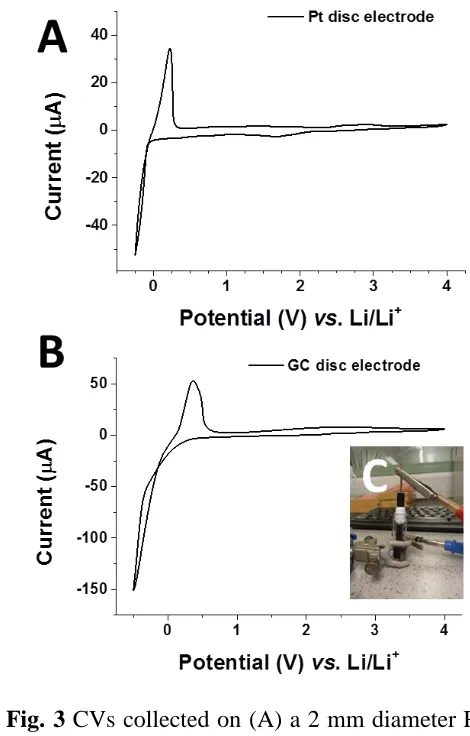
Fig. 3A and 3B shows clearly the electrochemical deposition and dissolution of lithium in 17
the ionic liquid electrolyte containing lithium salt on a 2 mm diameter Pt disc electrode and a 3 18
mm diameter Glass Carbon (GC) disc electrode, respectively. Fig 2C is the photo of the 19
homemade electrochemical cell, in which a working electrode (Pt or GC) and a piece of lithium 20
metal foil as both counter and reference electrodes are sealed in a vial. The electrolyte contains 21
0.01 mol L-1 LiClO4 in the mixture of BMPyrrFAP and γ-GBL (volume ratio 1:1). Lithium metal
22
stable in the electrolyte unless a positive scan occurs showing a dissolution peak in the CVs. The 1
over-potential on the GC electrode indicates an energy gap between condense carbon and lithium 2
surface. Another key information from Fig. 3 is that the ionic liquid solution used in this work 3
shows an electrochemical window more than 4 V using Pt and GC electrodes. The ionic liquid 4
solution could be a potential candidate for the supercapattery electrolyte. 5
6
Fig. 3 CVs collected on (A) a 2 mm diameter Pt disc electrode and (B) a 3 mm diameter Glass 7
Carbon disc electrode, in the mixture of BMPyrrFAP and γ-GBL (v:v = 1:1), contains 0.01 mol 8
L-1 LiClO4. Scan rate 10 mV s-1. Potential range: -0.25 ~ 4.00 V vs. Li/Li+. (C) Photo of the
9
homemade electrochemical cell. 10
[image:10.612.69.304.225.593.2]In a demonstrative supercapattery cell with lithium metal negative electrode, the redox 1
Li/Li+ reaction should be occurring during the charging or discharging process. A 0.5 mol L-1 2
LiClO4 ionic liquid solution was prepared as the electrolyte to provide sufficient Li-ion in the
3
electrolyte. The solvent content is the same as the one in the previous lithium deposition 4
experiment, BMPyrrFAP and γ-GBL (v:v = 1:1). The working electrode is a piece of 0.5 mg 5
Kuraray Act-C pellet coated on a 5 mm diameter graphite disc electrode with PVDF binder. The 6
counter and referenced electrodes are lithium metal foil. The cell was fabricated in an argon 7
filled glove box, sealed properly and then transferred outside the box for the further test. The CV 8
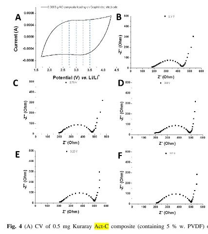
and AC impedance data of this cell is presented in Fig. 4. The blue dash lines on CV curve mark 9
the potential at which the AC impedance test was run. It should be mentioned again that the real 10
amount of lithium metal anticipating the charge storage process is negligible according the 11
previous calculation. The reason of placing a piece of lithium metal foil in the cell is to acquire 12
accurate potential result during the charging and discharging processes. From the CV in Fig. 4, 13
we found that the Kuraray Act-C can undergo a capacitor-like behaviour from the potential range 14
from 1.7 to 4.3 V vs. Li/Li+ at least. There is no obvious turning point to the clear oxidative or 15
reductive current on the CV curve. If we assumed this is capacitor behaviour, the calculated 16
specific capacitance value is 101 F g-1. The deformed rectangular CV shape should be caused by 17
the resistance of the whole cell, which is clearly shown in the Nyquist plots of the cell at 18
different potentials. Although the resistance of the cell shows a value about 180 Ω, the 19
equivalent series resistance (ESR) is about 35 Ω cm2
(area: 0.196 cm2), which is only 30 times 20
larger than the value got from a symmetrical aqueous AC supercapacitor using the same 21
acceptable range in practical devices. The optimization of this hybrid design is definitely needed 1
to increase output power. 2
3
Fig. 4 (A) CV of 0.5 mg Kuraray Act-C composite (containing 5 % w. PVDF) on a 5 mm 4
diameter Graphite disc electrode in mixture of BMPyrrFAP and γ-GBL (v/v = 1/1) containing 5
0.5 mol L-1 LiClO4. Scan rate: 10 mV s-1. Nyquist plots of the same cell at the potential of (B)
6
2.50 V, (C) 2.75 V, (D) 3.00 V, (E) 3.25 V, (F) 3.50 V vs Li/Li+. A Lithium foil was used as the 7
[image:12.612.58.485.129.609.2]1
2
Fig. 5 Galvanostatic charge-discharge curves of a pellet of 0. 5 mg Kuraray Act-C composite 3
(containing 5 % w. PVDF) on a 5 mm diameter graphite disc electrode in mixture of 4
BMPyrrFAP and γ-GBL (v/v = 1/1) containing 0.5 mol L-1 LiClO4. Current density: 1 mA cm-2.
5
6
The galvanostatic charge-discharge test was run under a current density of 1.02 mA cm-2. 7
Because the negative electrode is a lithium foil, the voltage of the cell decays smoothly and 8
linearly during the discharging process from 4.3 to 1.7 V. Because the charging and discharging 9
curve is almost symmetric, we still can calculate the specific capacitance and energy capacity by 10
the method for supercapacitor. The Act-C specific capacitance value comes to 107 F g-1 in the 11
ionic liquid solution containing LiClO4. Noted that only tiny amount of lithium metal takes part
12
[image:13.612.46.536.103.739.2]Lithium is only 6.94 g mol-1, we can ignore the mass of the negative electrode if the active 1
materials are counted only in the calculation of specific energy capacity. The value is 232 Wh 2
kg-1. 3
If we only chose an ionic liquid as the electrolyte, we can hardly use the available redox 4
couple resources to store charge in the energy storage devices. The Li-ion source ionic liquids 5
electrolyte can both supply sufficient charge carrier for the charge storage on the Act-C surface 6
and the necessary Li-ion for the chemical reaction. We do notice that the CV of the Act-C in a 7
pure ionic liquid show partly pseudo-capacitance behaviour. This is a preliminary proof for the 8
charge transfer or charge isolation process on the carbon surface. The advantage of the organic 9
electrolytes or ionic liquid electrolytes is that they can keep chemical and thermal stable in a 10
wider potential or temperature range than the one of aqueous electrolyte. Although recent studies 11
have revealed that some aqueous electrolyte can be superior to its analogous species on voltage8 12
and temperature limit,23 the variety and particularity of ionic liquids still make themselves 13
competitive in different application, especially in energy storage. This paper reveals a new idea 14
on using the Act-C materials as a positive electrode material in supercapattery. The following-up 15
work on further understanding the charge storage mechanism of Act-C in ionic liquids and 16
optimization of the hybrid design of the supercapattery in this paper is ongoing. 17
18
Conclusions 19
A hybrid supercapattery design comprising a lithium metal negative electrode and an 20
activated carbon positive electrode is presented and demonstrated using an experimental cell in 21
this paper. An ionic liquid was used as one component of the electrolyte containing LiClO4. The
22
liquid electrolyte. In the ionic liquid solution, the sufficient Li-ion in the ionic liquid electrolyte 1
provide additional charge carriers and enough charge storage species through the Li/Li+ redox 2
reaction. The energy capacity of the demonstrative supercapattery reaches to 232 Wh kg-1, while 3
the device can present capacitor-like behaviour when the Galvanostatic charge-discharge current 4
density is more than 1.0 mA cm-2, maintaining its high power output character. In addition, the 5
partly pseudo-capacitor behaviour of the activated carbon in ionic liquid reveal a possibility to 6
study the interaction of redox species inside the micropore structure of the activated carbon 7
materials. 8
9
Acknowledgements 10
This work received funding from the University of Nottingham Ningbo China and Ningbo 11
Municipal Government (3315 Plan and IAMET Special Fund, 2014A35001-1). Responsibility 12
for the content of this paper lies with the authors. 13
14
Notes and references 15
1. A. J. Stevenson, D. G. Gromadskyi, D. Hu, J. H. Chae, L. Guan, L. P. Yu and G. Z. Chen, in 16
Nanocarbons for Advanced Energy Storage, Vol. 1, ed. X. Feng, Wiley-VCH, Weinheim, 17
2015, 179-210. 18
2. S. W. Woo, K. Dokko, H. Nakano and K. Kanamura, Electrochemistry, 2007, 75, 635-640. 19
3. A. Krause, P. Kossyrev, M. Oljaca, S. Passerini, M. Winter and A. Balducci, J. Power 20
Sources, 2011, 196, 8836-8842. 21
4. K. C. Ng, S. W. Zhang, C. Peng and G. Z. Chen, J. Electrochem. Soc., 2009, 156, A846-22
5. S. W. Zhang, C. Peng, K. C. Ng and G. Z. Chen, Electrochim. Acta, 2010, 55, 7447-7453. 1
6. Z. Dai, C. Peng, J. H. Chae, K. C. Ng and G. Z. Chen, Sci. Rep., 2015, 5, 09854. 2
7. C. Peng, S. Zhang, X. Zhou and G. Z. Chen, Chem. Comm., 2010, 3, 1499-1502. 3
8. J. H. Chae and G. Z. Chen, Electrochim. Acta, 2012, 86, 248-254. 4
9. X. Zhou, C. Peng and G. Z. Chen, AIChE J., 2012, 58, 974-983. 5
10. S. Makino, Y. Shinohara, T. Ban, W. Shimizu, K. Takahashi, N. Imanishi and W. Sugimoto, 6
RSC Adv., 2012, 2, 12144-12147. 7
11. P. Wasserscheid and T. Welton (Eds.), Ionic Liquids in Synthesis, Wiley-VCH Verlag 8
Weinheim/Germany, 2002. 9
12. M. Oromi-Farrus, J. Eras, G. Villorbina, M. Torres, V. Llopis-Mestre, T. Welton and R. 10
Canela, Anal. Sci., 2008, 24, 1341-1345. 11
13. L. Chen, Y. Chi, X. Zheng, Y. Zhang and G. Chen, Anal. Chem., 2009, 81, 2394-2398. 12
14. T. Li, B. Li, S. Dong and E. Wang, Chem. Eur. J., 2007, 13, 8516-8521. 13
15. X. J. Wei, L. P. Yu, D. H. Wang, X. B. Jin and G. Z. Chen, Green Chem., 2008, 10, 296-305. 14
16. X. J. Wei, L. P. Yu, X. B. Jin, D. H. Wang and G. Z. Chen, Adv. Mater., 2009, 21, 776-780. 15
17. L. P. Yu and G. Z. Chen, RSC Adv., 2014, 4, 40281-40285. 16
18. M. Anouti, E. Couadou, L. Timperman and H. Galiano, Electrochim. Acta, 2012, 64, 110-17
117. 18
19. A. Orita, K. Kamijima and M. Yoshida, J. Power Sources, 2010, 195, 7471-7479. 19
20. M. Galinski and I. Stepniak, J. Appl. Electrochem., 2009, 39, 1949-1953. 20
21. D. G. Gromadskyi, J. H. Chae, S. A. Norman and G. Z. Chen, Appl. Energ., 2015, 159, 39-21
22. L. P. Yu, H.J. Sun, J. He, D. H. Wang, X. B. Jin, X. H. Hu and G.Z. Chen, Electrochem. 1
Commun., 2007, 9, 1374-1381. 2
23. Y. Gao, Z. Qin, L. Guan, X. Wang and G. Z. Chen, Chem. Commun., 2015, 51, 10819-3
10822. 4